


Resiliency
The reliability of systems starts with components, devices, and subsystems that are highly reliable. During the design and development process, subsystems go through rigorous verification and integration testing processes. During system manufacturing, systems go through a thorough testing process to help ensure the highest level of product quality.
Mathematically, reliability is defined in terms of how infrequently something fails.
At a system level, availability is about how infrequent failures cause workload interruptions. The longer the interval between interruptions, the more available a system is.
Serviceability is about how efficiently failures are identified and dealt with, and how application outages are minimized during repair.
The Power10 E1050 comes with the following reliability, availability, and serviceability (RAS) characteristics:
•Enterprise baseboard management controller (BMC) service processor for system management and service
•Open Memory Interface (OMI) and Differential Dual Inline Memory Modules (DDIMMS) RAS
•Power10 processor RAS
•I/O subsystem RAS
•Serviceability
These points are described in this chapter.
Additionally, the following points also are part of the Power E1050 RAS:
•Redundant and hot-plug cooling
•Redundant and hot-plug power
•Redundant voltage regulators
•Time of day battery concurrent maintenance
Table 4-1 shows the differences, from a RAS perspective, in the Power10 processor-based family.
Table 4-1 Power10 Servers RAS highlights comparison
|
Item
|
IBM Power S10xx
|
IBM Power E1050
|
IBM Power E1080
|
|
Base Power10 processor RAS features:
•First Failure Data Capture (FFDC)
•Processor Instruction Retry (PIR)
•L2/L3 Cache error correction code (ECC) protection with cache line-delete
•Power/cooling monitor function integrated into on-chip controllers of the processors
|
Yes.
|
Yes.
|
Yes.
|
|
Power10 Enterprise RAS feature: Core Checkstops
|
Yes.
|
Yes.
|
Yes.
|
|
Multi-node symmetric multiprocessing Fabric RAS: cyclic redundancy check (CRC)-checked processor fabric bus retry with spare data lane or bandwidth reduction
|
N/A.
|
N/A.
|
Yes. The Power10 processor-based design removes active components on cable and introduces internal cables to reduce backplane replacements.
|
|
Hot-plug with processor integrated
|
Yes.
|
Yes.
|
Yes.
|
|
Memory DIMM ECC supporting x4
|
Yes.
|
Yes.
|
Yes.
|
|
Dynamic Memory Row repair and spare dynamic RAM (DRAM) capability
|
2U DDIMM: No spare DRAM.
Yes: Dynamic Row Repair.
|
Yes: Base.
4U DDIMM with 2 spare DRAMs per rank.
Yes: Dynamic Row Repair.
|
Yes: Base.
4U DDIMM with 2 spare DRAMs per rank.
Yes: Dynamic Row Repair.
|
|
Active Memory Mirroring (AMM) for Hypervisor
|
Yes: Base.
New to scale-out.
|
Yes: Base.
|
Yes: Base.
|
|
Redundant or spare voltage phases on voltage converters for levels feeding processor
|
No.
|
Yes: N+1.
|
Yes: N+2.
|
|
Redundant On-board Power Management Integrated Circuits (PMICs) memory DDIMMs
|
No.
2U DDIMM.
|
Yes: Base.
4U DDIMM.
|
Yes: Base.
|
|
Service processor type
|
Enterprise Baseboard Management Controller (eBMC). Open standard with Redfish support.
|
eBMC. Open standard with Redfish support.
|
Flexible Service Processor (FSP). IBM proprietary.
|
|
Processor clocks redundancy/sparing
|
No.
|
No.
|
Redundant.
|
|
Redundant service processor and related boot facilities
|
No.
|
No.
|
Yes.
|
|
Redundant trusted platform module (TPM) capability
|
No.
|
No.
|
Yes.
|
|
Multi-node support
|
N/A.
|
N/A.
|
Yes.
|
4.1 Service processor
The Power10 E1050 comes with a redesigned service processor that is based on a BMC design with firmware that is accessible through open-source industry-standard application programming interfaces (APIs), such as Redfish. An upgraded Advanced System Management Interface (ASMI) web browser user interface preserves the required RAS functions while allowing the user to perform tasks in a more intuitive way.
Diagnostic monitoring of recoverable errors from the processor chipset is performed on the system processor itself, and the unrecoverable diagnostic monitoring of the processor chipset is performed by the service processor. The service processor runs on its own power boundary and does not require resources from a system processor to be operational to perform its tasks.
The service processor supports surveillance of the connection to the Hardware Management Console (HMC) and to the system firmware (hypervisor). It also provides several remote power control options, environmental monitoring, reset, restart, remote maintenance, and diagnostic functions, including console mirroring. The BMC service processors menus (ASMI) can be accessed concurrently during system operation, allowing nondisruptive abilities to change system default parameters, view and download error logs, and check system health.
Redfish, an industry-standard API for server management, enables IBM Power servers to be managed individually or in a large data center. Standard functions such as inventory, event logs, sensors, dumps, and certificate management are all supported by Redfish. In addition, new user management features support multiple users and privileges on the BMC through Redfish or ASMI. User management through lightweight directory access protocol (LDAP) also is supported. The Redfish events service provides a means for notification of specific critical events such that actions can be taken to correct issues. The Redfish telemetry service provides access to a wide variety of data (such as power consumption, and ambient, core, DIMMs, and I/O temperatures) that can be streamed at periodic intervals.
The service processor monitors the operation of the firmware during the boot process and also monitors the hypervisor for termination. The hypervisor monitors the service processor and reports a service reference code when it detects surveillance loss. In the PowerVM environment, it performs a reset/reload if it detects the loss of the service processor.
4.2 Memory subsystem RAS
The Power10 E1050 server introduces a new 4U tall (DDIMM) subsystem, which has a new OpenCAPI memory interface that is called OMI, for resilient and fast communication to the processor.

Figure 4-1 Power10 E1050 OMI
This new memory subsystem design delivers solid RAS. Unlike the processor RAS characteristics, the E1050 memory RAS varies significantly from that of the IBM Power E950. The Power E1050 supports the same 4U DDIMM height as the IBM Power E1080.
Table 4-2 compares memory DIMMs, and highlights the differences between the Power E950 DIMM and the Power E1050 DDIMM. It also provides the RAS impacts of the DDIMMs, which are applicable to the Power E1080 servers.
Table 4-2 Power E950 DIMMs versus Power E1050 DDIMMs RAS comparison
|
Item
|
Power E950 memory
|
Power E1050 memory
|
RAS impact
|
|
DIMM form factor
|
Riser card plus industry-standard DIMMs
|
4U DIMM
|
•Power E1050 4U DDIMM: Single field-replaceable unit (FRU) or fewer components to replace.
•Power E950 DIMM: A separate FRU is used for a memory buffer on a riser card and the industry-standard DIMMs.
|
|
Symbol correction
|
Single symbol correction
|
Dual symbol correction
|
•Power E1050 4U DDIMM: A data pin failure (1 symbol) that lines up with single cell failure on another DRAM is still correctable.
•Power E950 DIMM: A data pin failure (1 symbol) that lines up with single cell failure on another DRAM is uncorrectable.
|
|
X4 Chipkill
|
One spare DRAM across a DIMM repair
|
Single DRAM Chipkill correction plus
|
•Power E1050 4U DDIMM:
– First Chipkill is fixed with a spare.
– Second Chipkill is fixed with a spare.
– Third Chipkill is fixed with ECC.
– Fourth Chipkill is uncorrectable.
•Power E950 DIMM:
– First Chipkill is fixed with a spare.
– Second Chipkill is fixed with ECC.
– Third Chipkill is uncorrectable.
|
|
DRAM row repair
|
Static
|
Dynamic
|
•Power E1050 4U DDIMM: Detect, fix, and restore at run time without a system outage.
•Power E950 DIMM: Detect at run time, but a fix and restore requires a system restart.
|
|
L4 cache
|
Yes
|
No
|
•Power E1050 4U DDIMM: Avoids L4 cache failure modes.
•Power E950 DIMM: The L4 cache fail rate is a significant contributor to DIMM replacements.
|
|
Voltage regulation redundancy
|
No
|
Yes
|
•Power E1050 4U DDIMM: Can survive a voltage regulation component failure.
•Power E950 DIMM: Voltage regulation and associated components are a single point of failure.
|
4.2.1 Memory buffer
The DDIMM contains a memory buffer with key RAS features, including protection of critical data/address flows by using CRC, ECC, and parity; a maintenance engine for background memory scrubbing and memory diagnostics; and a Fault Isolation Register (FIR) structure, which enables firmware attention-based fault isolation and diagnostics.
4.2.2 Open Memory Interface
The OMI interface between the memory buffer and processor memory controller is protected by dynamic lane calibration, and a CRC retry/recovery facility to retransmit lost frames to survive intermittent bit flips. A lane fail also can be survived by triggering a dynamic lane reduction from 8 to 4, independently for both up and downstream directions. A key advantage of the OMI interface is that it simplifies the number of critical signals that must cross connectors from processor to memory compared to a typical industry-standard DIMM design.
4.2.3 Memory ECC
The DDIMM includes a robust 64-byte Memory ECC with 8-bit symbols, which can correct up to five symbol errors (one x4 chip and one additional symbol), and retry for data and address uncorrectable errors.
4.2.4 Dynamic row repair
To further extend the life of the DDIMM, the dynamic row repair feature can restore full use of a DRAM for a fault that is contained to a DRAM row while the system continues to operate.
4.2.5 Spare temperature sensors
Each DDIMM has spare temperature sensors so that the failure of one does not require a DDIMM replacement.
4.2.6 Spare DRAMs
4U DDIMMs include two spare x4 memory modules (DRAMs) per rank, which can be substituted for failed DRAMs during a runtime operation. Combined with ECC correction, the two spares allow a 4U DDIMM to continue to function with three bad DRAMs per rank, compared to 1 (single device data correct) or 2 (double device data correct) bad DRAMs in a typical industry-standard DIMM design. This setup extends self-healing capabilities beyond what is provided with the dynamic row repair capability.
4.2.7 Spare Power Management Integrated Circuits
4U DDIMMs include spare PMICs so that the failure of one PMIC does not require a DDIMM replacement.
4.3 Power10 processor RAS
Although there are many differences internally in the Power10 processor compared to the Power9 processor that relate to performance, number of cores, and other features, the general RAS philosophy for how errors are handled has remains the same. Therefore, information about Power9 processor-based subsystem RAS can still be referenced to understand the design. For more information, see Introduction to IBM Power Reliability, Availability, and Serviceability for Power9 processor-based systems using IBM PowerVM.
The Power E1050 processor module is a dual-chip module (DCM) that differs from that of the Power E950, which has single-chip module (SCM). Each DCM has 30 processor cores, which is 120 cores for a 4-socket (4S) Power E1050. In comparison, a 4S Power E950 supports
48 cores. The internal processor buses are twice as fast with the Power E1050 running at
32 Gbps.
48 cores. The internal processor buses are twice as fast with the Power E1050 running at
32 Gbps.
Despite the increased cores and the faster high-speed processor bus interfaces, the RAS capabilities are equivalent, with features like PIR, L2/L3 Cache ECC protection with cache line delete, and the CRC fabric bus retry that is a characteristic of Power9 and Power10 processors. As with the Power E950, when an internal fabric bus lane encounters a hard failure in a Power E1050, the lane can be dynamically spared out.
Figure 4-2 shows the Power10 DCM.

Figure 4-2 Power10 Dual-Chip Module
4.3.1 Cache availability
The L2/L3 caches in the Power10 processor in the memory buffer chip are protected with double-bit detect, single-bit correct ECC. In addition, a threshold of correctable errors that are detected on cache lines can result in the data in the cache lines being purged and the cache lines removed from further operation without requiring a restart in the PowerVM environment. Modified data is handled through Special Uncorrectable Error (SUE) handling. L1 data and instruction caches also have a retry capability for intermittent errors and a cache set delete mechanism for handling solid failures.
4.3.2 Special Uncorrectable Error handling
SUE handling prevents an uncorrectable error in memory or cache from immediately causing the system to terminate. Rather, the system tags the data and determines whether it will ever be used again. If the error is irrelevant, it will not force a checkstop. When and if data is used, I/O adapters that are controlled by an I/O hub controller freeze if the data were transferred to an I/O device; otherwise, termination can be limited to the program/kernel, or if the data is not owned by the hypervisor.
4.3.3 Uncorrectable error recovery
When the auto-restart option is enabled, the system can automatically restart following an unrecoverable software error, hardware failure, or environmentally induced (AC power) failure.
4.4 I/O subsystem RAS
The Power E1050 provides 11 general-purpose Peripheral Component Interconnect Express (PCIe) slots that allow for hot-plugging of I/O adapters, which makes the adapters concurrently maintainable. These PCIe slots operate at Gen4 and Gen5 speeds. Some of the PCIe slots support OpenCAPI and I/O expansion drawer cable cards.
Unlike the Power E950, the Power E1050 location codes start from index 0, as with all Power 10 systems. However, slot c0 is not a general-purpose PCIe slot because it is reserved for the eBMC Service Processor card.
Another difference between the Power E950 and the Power E1050 is that all the Power E1050 slots are directly connected to a Power10 processor. In the Power E950, some slots are connected to the Power9 processor through I/O switches.
All 11 PCIe slots are available if 3-socket or 4-socket DCMs are populated. In the 2-socket DCM configuration, only seven PCIe slots are functional.
DASD options
The Power E1050 provides 10 internal Non-volatile Memory Express (NVMe) drives at Gen4 speeds, which means that they are concurrently maintainable. The NVMe drives are connected to DCM0 and DCM3. In a 2-socket DCM configuration, only six of the drives are available. To access to all 10 internal NVMe drives, you must have a 4S DCM configuration. Unlike the Power E950, the Power E1050 has no internal serial-attached SCSI (SAS) drives You can use an external drawer to provide SAS drives.
The internal NVMe drives support OS-controlled RAID 0 and RAID 1 array, but no hardware RAID. For best redundancy, use an OS mirror and dual Virtual I/O Server (VIOS) mirror. To ensure as much separation as possible in the hardware path between mirror pairs, the following NVMe configuration is recommended:
•Mirrored OS: NVMe3 and NVMe4 pairs, or NVMe8 and NVMe9 pairs
•Mirrored dual VIOS:
– Dual VIOS: NVMe3 for VIOS1, NVMe4 for VIOS2.
– Mirrored dual VIOS: NVMe9 mirrors NVMe3, and NVMe8 mirrors NVMe4.
4.5 Serviceability
The purpose of serviceability is to efficiently repair the system while attempting to minimize or eliminate any impact to system operation. Serviceability includes system installation, Miscellaneous Equipment Specification (MES) (system upgrades/downgrades), and system maintenance or repair. Depending on the system and warranty contract, service may be performed by the client, an IBM representative, or an authorized warranty service provider. The serviceability features that are delivered in this system help provide a highly efficient service environment by incorporating the following attributes:
•Designed for IBM System Services Representative (IBM SSR) setup, install, and service.
•Error Detection and Fault Isolation (ED/FI).
•FFDC.
•Light path service indicators.
•Service and FRU labels that are available on the system.
•Service procedures are documented in IBM Documentation or available through the HMC.
•Automatic reporting of serviceable events to IBM through the Electronic Service Agent (ESA) Call Home application.
4.5.1 Service environment
In the PowerVM environment, the HMC is a dedicated server that provides functions for configuring and managing servers for either partitioned or full-system partition by using a GUI, command-line interface (CLI), or Representational State Transfer (REST) API. An HMC that is attached to the system enables support personnel (with client authorization) to remotely or locally (by using the physical HMC that is in proximity of the server being serviced) log in to review error logs and perform remote maintenance if required.
The Power10 processor-based servers support several service environments:
•Attachment to one or more HMCs or virtual HMCS (vHMCs) is a supported option by the system with PowerVM. This configuration is the default one for servers supporting logical partitions (LPARs) with dedicated or virtual I/O. In this case, all servers have at least one LPAR.
•No HMC. There are two service strategies for non-HMC systems:
– Full-system partition with PowerVM: A single partition owns all the server resources and only one operating system (OS) may be installed. The primary service interface is through the OS and the service processor.
– Partitioned system with NovaLink: In this configuration, the system can have more than one partition and can be running more than one OS. The primary service interface is through the service processor.
4.5.2 Service interface
Support personnel can use the service interface to communicate with the service support applications in a server by using an operator console, a GUI on the management console or service processor, or an OS terminal. The service interface helps to deliver a clear, concise view of available service applications, helping the support team to manage system resources and service information in an efficient and effective way. Applications that are available through the service interface are carefully configured and placed to grant service providers access to important service functions. Different service interfaces are used, depending on the state of the system, hypervisor, and operating environment. The primary service interfaces are:
•LEDs
•Operator panel
•BMC Service Processor menu
•OS service menu
•Service Focal Point (SFP) on the HMC or vHMC with PowerVM
In the light path LED implementation, the system can clearly identify components for replacement by using specific component-level LEDs and also can guide the servicer directly to the component by signaling (turning on solid) the enclosure fault LED and component FRU fault LED. The servicer also can use the identify function to flash the FRU-level LED. When this function is activated, a roll-up to the blue enclosure locate occurs. These enclosure LEDs turn on solid and can be used to follow the light path from the enclosure and down to the specific FRU in the PowerVM environment.
4.5.3 First Failure Data Capture and error data analysis
FFDC is a technique that helps ensure that when a fault is detected in a system, the root cause of the fault is captured without the need to re-create the problem or run any sort of extending tracing or diagnostics program. For most faults, a good FFDC design means that the root cause also can be detected automatically without servicer intervention.
FFDC information, error data analysis, and fault isolation are necessary to implement the advanced serviceability techniques that enable efficient service of the systems and to help determine the failing items.
In the rare absence of FFDC and Error Data Analysis, diagnostics are required to re-create the failure and determine the failing items.
4.5.4 Diagnostics
The general diagnostic objectives are to detect and identify problems so that they can be resolved quickly. Elements of th IBM diagnostics strategy include:
•Provides a common error code format equivalent to a system reference code with a PowerVM, system reference number, checkpoint, or firmware error code.
•Provides fault detection and problem isolation procedures. Supports remote connection, which can be used by the IBM Remote Support Center or IBM Designated Service.
•Provides interactive intelligence within the diagnostics with detailed online failure information while connected to the IBM back-end system.
4.5.5 Automatic diagnostics
The processor and memory FFDC technology is designed to perform without re-creating diagnostics or user intervention. Solid and intermittent errors are designed to be correctly detected and isolated at the time the failure occurs. Runtime and boot-time diagnostics fall into this category.
4.5.6 Stand-alone diagnostics
As the name implies, stand-alone or user-initiated diagnostics requires user intervention. The user must perform manual steps, including:
•Booting from the diagnostics CD, DVD, Universal Serial Bus (USB), or network
•Interactively selecting steps from a list of choices
4.5.7 Concurrent maintenance
The determination of whether a firmware release can be updated concurrently is identified in the readme file that is released with the firmware. An HMC is required for a concurrent firmware update with PowerVM. In addition, concurrent maintenance of PCIe adapters and NVMe drives is supported by PowerVM. Power supplies, fans, and operating panel LCDs are hot-pluggable.
4.5.8 Service labels
Service providers use these labels to assist them in performing maintenance actions. Service labels are found in various formats and positions are intended to transmit readily available information to the servicer during the repair process. Here are some of these service labels and their purposes:
•Location diagrams: Location diagrams are on the system hardware, relating information regarding the placement of hardware components. Location diagrams might include location codes, drawings of physical locations, concurrent maintenance status, or other data that is pertinent to a repair. Location diagrams are especially useful when multiple components such as DIMMs, processors, fans, adapters, and power supplies are installed.
•Remove/replace procedures: Service labels that contain remove/replace procedures are often found on a cover of the system or in other spots accessible to the servicer. These labels provide systematic procedures, including diagrams detailing how to remove or replace certain serviceable hardware components.
•Arrows: Numbered arrows are used to indicate the order of operation and the serviceability direction of components. Some serviceable parts such as latches, levers, and touch points must be pulled or pushed in a certain direction and in a certain order for the mechanical mechanisms to engage or disengage. Arrows generally improve the ease of serviceability.
4.5.9 QR labels
QR labels are placed on the system to provide access to key service functions through a mobile device. When the QR label is scanned, it goes to a landing page for Power10 processor-based systems, which contains each machine type and model (MTM) service functions of interest while physically at the server. These functions include things installation and repair instructions, reference code lookup, and other items.
4.5.10 Packaging for service
The following service features are included in the physical packaging of the systems to facilitate service:
•Color coding (touch points): Blue-colored touch points delineate touch points on service components where the component can be safely handled for service actions, such as removal or installation.
•Tool-less design: Selected IBM systems support tool-less or simple tool designs. These designs require no tools or simple tools such as flathead screw drivers to service the hardware components.
•Positive retention: Positive retention mechanisms help to ensure proper connections between hardware components, such as cables to connectors, and between two cards that attach to each other. Without positive retention, hardware components run the risk of becoming loose during shipping or installation, preventing a good electrical connection. Positive retention mechanisms like latches, levers, thumbscrews, pop nylatches (U-clips), and cables are included to help prevent loose connections and aid in installing (seating) parts correctly. These positive retention items do not require tools.
4.5.11 Error handling and reporting
In a system hardware or environmentally induced failure, the system runtime error capture capability systematically analyzes the hardware error signature to determine the cause of failure. The analysis result is stored in system NVRAM. When the system can be successfully restarted either manually or automatically, or if the system continues to operate, the error is reported to the OS. Hardware and software failures are recorded in the system log. When an HMC is attached in the PowerVM environment, an ELA routine analyzes the error, forwards the event to the SFP application running on the HMC, and notifies the system administrator that it has isolated a likely cause of the system problem. The service processor event log also records unrecoverable checkstop conditions, forwards them to the SFP application, and notifies the system administrator.
The system can call home through the OS to report platform-recoverable errors and errors that are associated with PCI adapters or devices.
In the HMC-managed environment, a Call Home service request is initiated from the HMC, and the pertinent failure data with service parts information and part locations is sent to an IBM service organization. Customer contact information and specific system-related data, such as the MTM and serial number, along with error log data that is related to the failure, are sent to IBM Service.
4.5.12 Live Partition Mobility
With PowerVM Live Partition Mobility (LPM), users can migrate an AIX, IBM i, or Linux VM partition running on one IBM Power partition server to another IBM Power server without disrupting services. The migration transfers the entire system environment, including processor state, memory, attached virtual devices, and connected users. It provides continuous OS and application availability during planned partition outages for repair of hardware and firmware faults. The Power10 servers that use Power10 processor-based technology support secure LPM, where the VM image is encrypted and compressed before transfer. Secure LPM uses on-chip encryption and compression capabilities of the Power10 processor for optimal performance.
4.5.13 Call Home
Call Home refers to an automatic or manual call from a client location to the IBM support structure with error log data, server status, or other service-related information. Call Home invokes the service organization in order for the appropriate service action to begin. Call Home can be done through the ESA that is embedded in the HMC, or through a version of the ESA that is embedded in the OSs for non-HMC-managed or a version of ESA that runs as a stand-alone Call Home application. While configuring Call Home is optional, clients are encouraged to implement this feature to obtain service enhancements such as reduced problem determination and faster and potentially more accurate transmittal of error information. In general, using the Call Home feature can result in increased system availability.
4.5.14 IBM Electronic Services
ESA and Client Support Portal (CSP) comprise the IBM Electronic Services solution, which is dedicated to providing fast, exceptional support to IBM clients. ESA is a no-charge tool that proactively monitors and reports hardware events, such as system errors, and collects hardware and software inventory. ESA can help focus on the client's company business initiatives, save time, and spend less effort managing day-to-day IT maintenance issues. In addition, Call Home Cloud Connect Web and Mobile capability extends the common solution and offers IBM Systems related support information that is applicable to servers and storage.
For more information, see IBM Call Home Connect Cloud.
4.6 Reliability and availability
This section looks at the more general concept of RAS as it applies to any system in the data center.
The goal is to briefly define what RAS is and look at how reliability and availability are measured.
4.6.1 Reliability modeling
The prediction of system level reliability starts with establishing the failure rates of the individual components that make up the system. Then, by using the appropriate prediction models, the component-level failure rates are combined to provide a system-level reliability prediction in terms of a failure rate.
However, in documentation system-level reliability is often described in terms of mean time between failures (MTBF) for repairable systems rather than a failure rate, for example,
50 years MTBF.
50 years MTBF.
A 50-year MTBF might suggest that a system runs 50 years between failures, but what it actually means is that among 50 identical systems, one per year will fail on average over a large population of systems.
4.6.2 Different levels of reliability
When a component fails, the impact of that failure can vary depending on the component.
A power supply failing in a system with a redundant power supply must be replaced. However, by itself a failure of a single power supply should not cause a system outage, and it should be a concurrent repair with no downtime.
Other components in a system might fail and cause a system-wide outage where concurrent repair is not possible. Therefore, it is typical to talk about different MTBF numbers:
•MTBF – Results in repair actions.
•MTBF – Requires concurrent repair.
•MTBF – Requires a non-concurrent repair.
•MTBF – Results in an unplanned application outage.
•MTBF – Results in an unplanned system outage.
4.6.3 Measuring availability
Mathematically speaking, availability is often expressed as a percentage of the time that something is available or in use over a period. An availability number for a system can be mathematically calculated from the expected reliability of the system if both the MTBF and the duration of each outage is known.
For example, consider a system that always runs exactly one week between failures and each time it fails it is down for 10 minutes. For 168 hours in a week, the system is down (10/60) hours. It is up 168 hrs – (10/60) hrs. As a percentage of the hours in the week, it can be said that the system is (168-(1/6))*100% = 99.9% available.
99.999% available means approximately 5.3 minutes of downtime in a year. On average, a system that failed once a year and was down for 5.3 minutes would be 99.999% available. This concept is often called “five 9s of availability”.
When talking about modern server hardware availability, short weekly failures like in the example is not the norm. Rather, the failure rates are much lower, and the MTBF is often measured in terms of years, perhaps more years than a system will be kept in service.
Therefore, when an MTBF of 10 years, for example, is quoted, it is not expected that on average each system will run 10 years between failures. Rather, it is more reasonable to expect that on average in a year that 1 server out of 10 will fail. If a population of 10 servers always had exactly one failure a year, a statement of 99.999% availability across that population of servers would mean that the one server that failed would be down about 53 minutes when it failed.
In theory, five 9s of availability can be achieved by having a system design that fails frequently, multiple times a year, but whose failures are limited to small periods of time. Conversely, five 9 s of availability might mean a server design with a large MTBF, but where a server takes a fairly long time to recover from the rare outage.
Figure 4-3 shows that five 9s of availability can be achieved with systems that fail frequently for minuscule amounts of time, or infrequently with much larger downtime per failure.
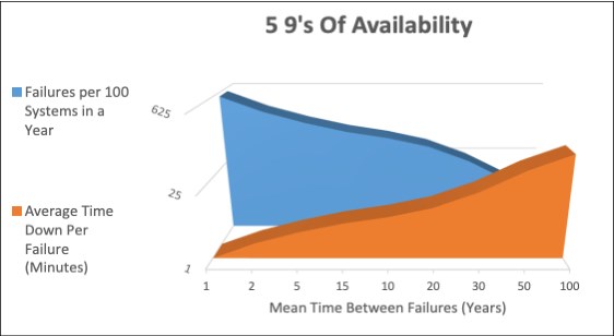
Figure 4-3 Five 9s of availability
Figure 4-3 on page 136 is misleading in the sense that servers with low reliability are likely to have many components that, when they fail, take down the system and keep the system down until repair. Conversely, servers that are designed for great reliability often also are designed so that the systems, or at least portions of the system, can be recovered without having to keep a system down until it is repaired. So, systems with low MTBF would have longer repair times, and a system with five 9s of availability would be synonymous with a high level of reliability.
..................Content has been hidden....................
You can't read the all page of ebook, please click here login for view all page.