

Implementing IP replication in the SVC/Storwize family
This chapter covers the steps required to configure Internet Protocol (IP) replication in the IBM System Storage SAN Volume Controller (SVC)/IBM Storwize family of products using the web-based graphical user interface (GUI). A detailed description of the example environment is provided. For details about using the command-line interface (CLI) to configure IP replication, see Appendix A, “Command-line interface” on page 53.
The following sections will describe the steps to configure an IP replication partnership between two SVC clusters, and to create and initiate a remote-copy relationship of volumes between these partner systems.
3.1 Configuring IP replication
The following sections describe how to configure IP replication.
3.1.1 Overview of required steps
Before configuring IP replication, ensure that the following prerequisites have been met:
1. Confirm the presence and details of the intersite IP links to be used for replication traffic between your partner systems. For more details about the requirements for intersite links, see Chapter 2, “IP replication configuration overview and considerations” on page 11.
2. Determine the number of Ethernet ports and replication port groups to be used.
3. Obtain IP addresses for the IP ports to be used, and ensure that the intersite links support the routing of traffic between the addresses on each end, and that Transmission Control Protocol (TCP) ports 3260 and 3265 are open for traffic between the partner systems.
To configure IP replication, the following steps must be performed:
1. Configure the Ethernet ports on each of the partner systems.
2. Create the IP partnership on each of the partner systems.
3. Create the wanted remote-copy relationship(s).
3.1.2 Physical details of an example environment
The configuration examples reference a lab environment containing two SVC clusters. Each SVC cluster contains two nodes. Our intersite connectivity consists of two 1 gigabits per second (Gbps) links. For the IP replication traffic, the example uses port 2 on each SVC node.
The example configuration in Figure 3-1 shows the two SVC clusters used to demonstrate IP replication in this paper.

Figure 3-1 Example configuration
This example highlights the following elements of the configuration:
•One SVC named ITSO_Local_Cluster and one SVC named ITSO_Remote_Cluster. Both systems use IBM XIV Storage Systems for back-end storage.
•This example uses network port 2 on each of the SVC nodes for IP replication, with two
1 Gbps intersite links.
1 Gbps intersite links.
•Because Global Mirror with Change Volumes (GM/CV) is the advised method to use with IP replication, GM/CV is used in the following examples.
The following sections provides details about the SVC clusters.
ITSO_Local_Cluster
ITSO_Local_Cluster has the following characteristics:
Cluster IP address 9.32.248.174
Node 1 port 2
IP address 192.168.1.10
Subnet mask 255.255.255.0
Gateway 192.168.1.1
Remote port group Group 1
Node 2 port 2
IP address 192.168.1.11
Subnet mask 255.255.255.0
Gateway 192.168.1.1
Remote port group Group 2
Master volumes (17 gigabytes, or GB)
repl_master_1
repl_master_2
repl_master_3
repl_master_4
Master change volumes (17 GB)
repl_master_cv_1
repl_master_cv_2
repl_master_cv_3
repl_master_cv_4
ITSO_Remote_Cluster
ITSO_Remote_Cluster has the following characteristics:
Cluster IP address 9.32.248.89
Node 1 port 2
IP address 192.168.1.12
Subnet mask 255.255.255.0
Gateway 192.168.1.1
Remote port group Group 1
Node 2 port 2
IP address 192.168.1.13
Subnet mask 255.255.255.0
Gateway 192.168.1.1
Remote port group Group 2
Auxiliary volumes (17 GB)
repl_auxiliary_1
repl_auxiliary_2
repl_auxiliary_3
repl_auxiliary_4
Auxiliary change volumes (17 GB)
repl_auxiliary_cv_1
repl_auxiliary_cv_2
repl_auxiliary_cv_3
repl_auxiliary_cv_4
|
Information: The IP addresses (IPs) used in this scenario are just one example of what IPs can be used. Any range of IPs are allowable, private networks included, if they conform with your own IP network and the requirements described in 2.1.2, “IP partnership requirements” on page 13.
|
3.1.3 Configure the Ethernet ports on the partner systems
This section describes the steps to configure the IP ports on the partner systems.
|
Remember: In the lab environment used for the examples in this section, Ethernet port 2 is configured on each of the two SVC nodes on the partner systems. Alternative Ethernet port configurations are supported. See 2.1, “IP partnerships” on page 12 for more information about the various supported configurations.
|
Configuring the Ethernet ports on ITSO_Local_Cluster
To configure the IP ports on ITSO_Local_Cluster, follow these steps:
1. Access the Network pane in the web-based GUI using the Settings icon in the left navigation menu, as show in Figure 3-2.

Figure 3-2 Accessing the Network pane in the web-based GUI

Figure 3-3 Accessing the Ethernet Ports pane in the web-based GUI
3. Right-click the row of the wanted port and select Modify to modify its IP settings, as shown in Figure 3-4. In this example, configure port 2 on node 1.

Figure 3-4 Modifying Ethernet Port settings in the web-based GUI
4. In the Modify Port dialog window shown in Figure 3-5 on page 26, enter the appropriate values for IP address, Subnet mask, and Gateway. In this example, the following values were used for port 2 on node 1:
IP address 192.168.1.10
Subnet mask 255.255.255.0
Gateway 192.168.1.1
iSCSI hosts Disabled
Remote copy Group 1
5. Additionally, select or clear the iSCSI hosts box to enable or disable Internet Small Computer System Interface (iSCSI) host traffic on this port. In this example, clear the box to disable iSCSI traffic on this port.
|
Tip: Although the sharing of IP ports for both IP replication traffic and iSCSI host traffic is supported, for performance purposes, it is advised to isolate IP replication traffic. For more information, see Chapter 2, “IP replication configuration overview and considerations” on page 11.
|
6. To enable the port for IP replication, use the Remote copy radio buttons to select a port group. In this example, choose Group 1 for Ethernet port 2, as shown in Figure 3-5.

Figure 3-5 Configuring Ethernet Port settings in the web-based GUI
7. When you click OK, the Modify Ethernet Port IP address dialog window will display the task status for modifying the Ethernet port IP address settings, as shown in Figure 3-6. After the task completes, click Close to close the task status window.

Figure 3-6 Task status for Ethernet port IP address modification in the web-based GUI
8. The Ethernet Ports pane should now reflect the changes made, as shown in Figure 3-7. Ensure that your settings are correct.

Figure 3-7 Verifying Ethernet Port settings for port 2 on node 1 in the web-based GUI
9. Repeat steps 3 on page 25 to 8 to configure the IP settings for port 2 on node 2. In this example, the following values were used for port 2 on node 2:
IP address 192.168.1.11
Subnet mask 255.255.255.0
Gateway 192.168.1.1
iSCSI hosts Disabled
Remote copy Group 2
10. The Ethernet Ports pane should now reflect the changes made to port 2 on node 2, as shown in Figure 3-8.

Figure 3-8 Verifying Ethernet Port settings for port 2 on node 2 in the web-based GUI
Configuring the Ethernet ports on ITSO_Remote_Cluster
To configure the IP ports on ITSO_Remote_Cluster, access the web-based GUI of ITSO_Remote_Cluster and repeat the procedure outlined in “Configuring the Ethernet ports on ITSO_Local_Cluster” on page 24, using the appropriate values. In this example, configure the Ethernet Ports on ITSO_Remote_Cluster using the following values:
Port 2 on Node 1
IP address 192.168.1.12
Subnet mask 255.255.255.0
Gateway 192.168.1.1
iSCSI hosts Disabled
Remote copy Group 1
Port 2 on Node 2
IP address 192.168.1.13
Subnet mask 255.255.255.0
Gateway 192.168.1.1
iSCSI hosts Disabled
Remote copy Group 2
Figure 3-9 shows the port configuration for the Ethernet Ports on ITSO_Remote_Cluster.

Figure 3-9 Verifying Ethernet Port settings for ITSO_Remote_Cluster in the web-based GUI
The Ethernet port settings are now complete, and you can proceed to configure the IP partnership.
3.1.4 Create and configure the IP partnership on each of the partner systems
In this section, we detail the steps to configure the IP partnership on the partner systems.
|
Remember: To create a Partnership between SVC and Storwize family systems, those systems must be in the same layer. SVC systems are always in the replication layer. Storwize systems are in the storage layer by default, but can be configured in the replication layer. To create a partnership between an SVC and a Storwize system, you must ensure that the Storwize system layer is set to replication. For more information, see 2.1.2, “IP partnership requirements” on page 13.
For information about troubleshooting IP partnership layer issues, see 4.2.2, “Error code CMMVC8354E” on page 48.
|
Configuring the IP partnership on ITSO_Local_Cluster
To configure the IP partnership on ITSO_Local_Cluster, perform the following steps:
1. Access the Partnerships pane in the web-based GUI using the Copy Services icon in the left navigation menu, as shown in Figure 3-10 on page 29.

Figure 3-10 Accessing the Partnerships pane in the web-based GUI

Figure 3-11 Creating a partnership in the web-based GUI

Figure 3-12 Selecting IP partnership replication type in the web-based GUI
4. In the Create Partnership dialog window shown in Figure 3-13 on page 30, enter values for Partner system IP address, Link bandwidth, Background copy rate, and optionally, Partner system’s CHAP secret. In this example, the following values were used:
Partner system IP address 9.32.248.89
Link bandwidth in megabits per second (Mbps)
2000 (our example environment contains two
1 Gbps intersite links)
1 Gbps intersite links)
Background copy rate (%) 50 (we chose to use up to 50% of the link bandwidth for the initial background synchronization)
Partner system’s CHAP secret None (the example environment does not use CHAP authentication)
|
Tip: For the partner system IP address, enter the management IP address (“cluster IP”) for the partner system. Do not enter the IP addresses that you configured for IP replication on the Ethernet ports of the partner system.
|
Figure 3-13 shows the example values.

Figure 3-13 Configuring IP partnership settings in the web-based GUI
5. When you click OK, the Create IP Partnership dialog window will display the task status for creating the IP partnership, as shown in Figure 3-14. When the task completes, click Close to close the task status window.

Figure 3-14 Task status for IP partnership creation in the web-based GUI
6. Confirm that the Partnerships pane displays the new partnership that you just created, as shown in Figure 3-15.

Figure 3-15 Verifying IP partnership creation in the web-based GUI
|
Note: Make note of the State of the partnership. When the partnership is successfully created on the first system, the State value on that system will display Partially Configured: Local. When the partnership is successfully created on the second system, the State on that system might initially display Not Present. After a brief period of time, the State value will display Fully Configured on each system if the IP partnership was successfully created on each partner system.
For further information about troubleshooting IP partnership creation, see Chapter 4, “Best practices and troubleshooting” on page 45.
|
Configuring the IP partnership on ITSO_Remote_Cluster
To configure the IP partnership on ITSO_Remote_Cluster, access the web-based GUI of ITSO_Remote_Cluster and repeat the procedure outlined in “Configuring the IP partnership on ITSO_Local_Cluster” on page 28, using the appropriate values. In this example, configure the IP partnership on ITSO_Remote_Cluster using the following values:
Partner system IP address 9.32.248.174
Link bandwidth (Mbps) 2000 (the example environment contains two 1 Gbps intersite links)
Background copy rate (%) 50 (we chose to use up to 50% of the link bandwidth for the initial background synchronization)
Partner system’s CHAP secret None (our example environment does not use CHAP authentication
After initially configuring the IP partnership on ITSO_Remote_Cluster, the Partnerships pane shows the state of this partnership as Not Present, as shown in Figure 3-16.

Figure 3-16 Initial IP partnership state on ITSO_Remote_Cluster in the web-based GUI
After a few moments, the State of the IP partnership should display Fully Configured on both systems, as shown in Figure 3-17 and Figure 3-18.

Figure 3-17 Fully configured IP partnership on ITSO_Local_Cluster in the web-based GUI

Figure 3-18 Fully configured IP partnership on ITSO_Remote_Cluster in the web-based GUI
The IP partnership is now fully configured, and you can proceed to configure the remote-copy relationships.
3.1.5 Creating IP remote-copy consistency groups and relationships
This section describes how to configure and activate remote-copy relationships that will use the IP replication partnership created in 3.1.4, “Create and configure the IP partnership on each of the partner systems” on page 28. Although IP replication supports all three types of remote-copy relationships (Metro Mirror (MM), Global Mirror (GM), and GM/CV), the advised remote-copy relationship type for use with IP replication is GM/CV. The following example shows relationships created using GM/CV.
Prerequisites and example environment details
To successfully create a remote-copy relationship, you must ensure that, for each volume that you want to replication, the remote partner system that you want to replicate to contains an available auxiliary volume that is the same size as the master volume. In this example, ITSO_Local_Cluster contains the following four 17 GB master volumes:
•repl_master_1
•repl_master_2
•repl_master_3
•repl_master_4
ITSO_Local_Cluster also contains the following four change volumes:
•repl_master_cv_1
•repl_master_cv_2
•repl_master_cv_3
•repl_master_cv_4
Additionally, ITSO_Remote_Cluster contains the following four 17 GB auxiliary volumes:
•repl_auxiliary_1
•repl_auxiliary_2
•repl_auxiliary_3
•repl_auxiliary_4
It also contains the following four change volumes:
•repl_auxiliary_cv_1
•repl_auxiliary_cv_2
•repl_auxiliary_cv_3
•repl_auxiliary_cv_4
The example uses a consistency group called ITSO_Repl_CG to contain the 4 volumes that we will replicate from ITSO_Local_Cluster to ITSO_Remote_Cluster.
Creating IP remote-copy consistency group and relationships on ITSO_Local_Cluster
To create a remote-copy relationship, perform the following steps:
1. Access the Remote Copy pane in the web-based GUI of ITSO_Local_Cluster using the Copy Services icon in the left navigation menu, as shown in Figure 3-19.

Figure 3-19 Accessing the Remote Copy pane in the web-based GUI
2. On the Remote Copy pane, click New Consistency Group at the top of the pane to create a consistency group containing multiple remote-copy relationships, as shown in Figure 3-20. Alternatively, if you choose not to use a consistency group, click New Relationship at the top of the pane to create a remote-copy relationship for a single volume.

Figure 3-20 Creating a remote-copy relationship in the web-based GUI
3. In the New Consistency Group dialog window, enter the Consistency Group Name and click Next, as shown in Figure 3-21.

Figure 3-21 Creating a New Consistency Group for IP Replication in the web-based GUI
4. In the New Consistency Group dialog window, indicate the location of the auxiliary volumes and click Next, as shown in Figure 3-22. In this example, the auxiliary volumes are located on ITSO_Remote_Cluster, called ITSO_Remote_Cluster.

Figure 3-22 Indicating the location of the auxiliary volumes in the web-based GUI
5. In the New Consistency Group dialog window, indicate whether you want to add remote-copy relationships to the consistency group now or later and click Next, as shown in Figure 3-23. In this example, choose to add the relationships now.

Figure 3-23 Indicating when to add remote-copy relationships to the consistency group in the web-based GUI
6. In the New Consistency Group dialog window, indicate the type of remote-copy relationship you want to add and click Next, as shown in Figure 3-24. In this example, choose Global Mirror with Change Volumes.

Figure 3-24 Choosing the type of remote-copy relationship in the web-based GUI
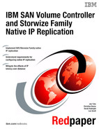
7. In the New Consistency Group dialog window, select any existing remote-copy relationships you want to add to this consistency group, as shown in Figure 3-25. In this example, choose to create new relationships, so click Next.
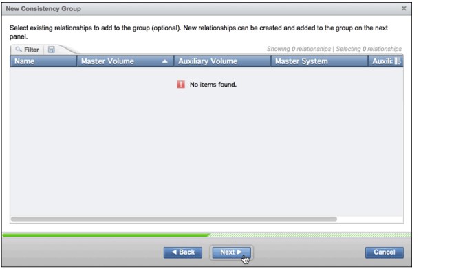
Figure 3-25 Selecting existing remote-copy relationships, if any, in the web-based GUI
8. In the New Consistency Group dialog window, use the drop-down menus to select the master and auxiliary volume relationship pairs, as shown in Figure 3-26.

Figure 3-26 Selecting primary and auxiliary relationship volumes in the web-based GUI
9. Click Add to create a relationship between each selected pair. For each pair that you add, the Add New Global Mirror Change Volume dialog window displays, as shown in Figure 3-27.

Figure 3-27 Indicating when to add master change volumes in the web-based GUI
10. You can choose to create or add the master Global Mirror change volume at this point, or after the consistency group has been fully created. In this example, choose to add the master change volumes at this step and click Next.
|
Important: Master change volumes can be created or added at this step, or at a later point. You must create or add auxiliary change volumes from the auxiliary system GUI or CLI after the remote-copy relationships have been added, or after the consistency group configuration is complete. The remote-copy relationship cannot be started until the change volumes have been created or added to the relationship for the master and auxiliary volumes.
|
11. In the Add New Global Mirror Change Volume dialog window, use the radio buttons to indicate whether you want to create a new master change volume, or use an existing master change volume, as shown in Figure 3-28. In this example, you indicate that you will use an existing master change volume, then use the drop-down menu to select it. Click Finish to complete adding this relationship to the consistency group.

Figure 3-28 Selecting the master Global Mirror change volume in the web-based GUI
Figure 3-29 shows that the New Consistency Group dialog window updates to reflect the remote-copy relationship that you just added to the consistency group.
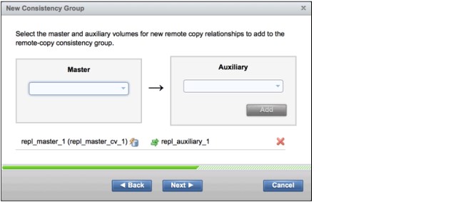
Figure 3-29 A new remote-copy relationship added to a new Consistency Group in the web-based GUI
12. Repeat steps 8 on page 36 through 11 on page 37 for any additional remote-copy master and auxiliary volume relationships that you want to add to the consistency group. In this example, add the remaining three master/auxiliary volume relationships, as shown in Figure 3-30, and click Next.
Figure 3-30 Four remote-copy relationships added to the consistency group in the web-based GUI
13. In the New Consistency Group dialog window, use the radio buttons to indicate whether the master and auxiliary volumes are already synchronized, as shown in Figure 3-31. In this example, indicate that the volumes are not synchronized, and then click Next.

Figure 3-31 Indicating remote-copy volume synchronization state in the web-based GUI
14. In the New Consistency Group dialog window, use the radio buttons to indicate whether you want to start copying the volumes now or later, as shown in Figure 3-32. In this example, choose to use Global Mirror with Change Volumes. In this scenario, you must add the change volumes on the auxiliary system before you can start copying, so choose not to start copying and click Finish.

Figure 3-32 Selecting when to start copying the consistency group in the web-based GUI
15. The Create Remote-Copy Consistency Group dialog window displays the task status for creating the remote-copy consistency group, as shown in Figure 3-33. When the task completes, click Close to close the task status window.

Figure 3-33 Task status for remote-copy consistency group creation in the web-based GUI
16. Confirm that the Remote Copy pane displays the consistency group and related remote-copy relationships that you just created, as shown in Figure 3-34.

Figure 3-34 Verifying remote-copy consistency group creation in the web-based GUI
|
Note: Make note of the State of the consistency group and remote-copy relationships. In the example environment, we chose to use GM/CV. In this scenario, the consistency group cannot be started until you configure the change volumes on the auxiliary system. When creating consistency groups without change volumes, you might choose to start the copying as soon as the consistency group is created. In those cases, the value displayed for the State of the consistency group might differ.
For further information about consistency groups and remote copy status, see Chapter 2, “IP replication configuration overview and considerations” on page 11.
|
Completing IP remote-copy consistency group and relationship configuration on ITSO_Remote_Cluster
To complete the configuration, perform the following steps:
1. Access the Remote Copy pane in the web-based GUI of ITSO_Remote_Cluster using the Copy Services icon in the left navigation menu, as shown in Figure 3-35.

Figure 3-35 Accessing the Remote Copy pane in the web-based GUI
2. On the Remote Copy pane, you will see the same consistency group that was created on ITSO_Local_Cluster, as shown in Figure 3-36. If necessary, expand the consistency group to display the associated remote-copy relationships.

Figure 3-36 Verifying the Partner System consistency group in the web-based GUI
3. Right-click the row for the first remote-copy relationship and use the Global Mirror Change Volumes menu to add a change volume to this auxiliary volume. You can choose to create a new change volume or add an existing volume. In this example, choose to use an existing volume, so select Global Mirror Change Volumes → Add Existing, as shown in Figure 3-37.

Figure 3-37 Adding auxiliary change volumes in the web-based GUI
4. In the Add Existing Global Mirror Change Volume dialog window, use the drop-down menu to select the appropriate auxiliary change volume, and click Add, as shown in Figure 3-38.

Figure 3-38 Selecting the auxiliary change volume in the web-based GUI
5. The Add Global Mirror Change Volume dialog window displays the task status for adding the change volume, as shown in Figure 3-39. When the task completes, click Close to close the task status window.

Figure 3-39 Task status for adding a change volume in the web-based GUI
6. Repeat steps 3 on page 41 and 4 on page 41 for each of the remaining remote-copy relationships in the consistency group.
Starting the IP remote-copy consistency group
To start the IP remote-copy consistency group, perform the following steps:
1. After all of the auxiliary change volumes have been added to the consistency group, right-click the consistency group in the Remote Copy pane and select Start to start the consistency group, as shown in Figure 3-40.

Figure 3-40 Starting the IP replication remote-copy consistency group in the web-based GUI
2. The Start Remote-Copy Consistency Group dialog window displays the task status for starting the consistency group, as shown in Figure 3-41 on page 43. When the task completes, click Close to close the task status window.

Figure 3-41 Task status for starting a remote-copy consistency group in the web-based GUI
Verifying and monitoring IP remote-copy status
To verify and monitor the IP remote-copy status, perform the following steps:
1. The Remote Copy pane should indicate that the consistency group state is now Inconsistent Copying, as shown in Figure 3-42.

Figure 3-42 Verifying remote-copy consistency group state in the web-based GUI
2. Additionally, you can verify that the expected Ethernet ports are in use for IP replication by clicking Settings → Network from the left navigation menu, then accessing the Network → Ethernet Ports pane, as shown in Figure 3-43. Note the value in the Remote Copy Active column.

Figure 3-43 The Ethernet Ports pane
3. Further, you can monitor the IP remote-copy bandwidth usage of the system from the Performance page. From the left navigation menu, choose Monitoring → Performance menu, as shown in Figure 3-44.

Figure 3-44 Accessing the Performance page in the web-based GUI
4. In the Interfaces graph in the lower left region of the Performance pane, ensure that the IP Remote Copy box is selected, as shown on Figure 3-45. When selected, the graph will display IP Remote Copy statistics.

Figure 3-45 Monitoring IP Remote Copy performance in the web-based GUI
..................Content has been hidden....................
You can't read the all page of ebook, please click here login for view all page.