


Planning for an N series and VMware vSphere 4.1
This chapter explains how to plan the setup of an N series and VMware ESXi installation. It includes the following topics:
•Planning requirements
•Overview of solution sizing
•Planning for the virtualized solution
•Configuration limits and guidance
•vol options <vol-name> no_atime_update on
•Storage provisioning
•Storage connectivity
•Networking for IP storage
•Increasing storage utilization
•Snapshots
•Backup and recovery
•N series FlexShare
•Licensing
4.1 Planning requirements
The first step to be taken when implementing a new technology is planning. This step is often underestimated because of lack of knowledge and the non-immediate results of an unplanned system.
The aim is to have a long lasting implementation with as few problems as possible. This chapter discusses some considerations you need to keep in mind when planning your environment and the integration of its components.
4.1.1 Compatibility and support
The first step in ensuring the feasibility of a solution is to check its compatibility. Both hardware and software must be certified and supported to work with each other. Otherwise, you might not have support from the vendors if needed.
Because your server hardware might be from different vendors, we are providing the storage and software compatibility references.
4.1.2 Data ONTAP
Although Data ONTAP has supported VMware products since the introduction of the N series product line, this support is continually being enhanced. See the “IBM System Storage N series and TotalStorage NAS interoperability matrices” web page at the following address for the latest supported solutions:
|
Access to IBM Systems support: You must register for access to IBM Systems support applications and content. You can register at the following address:
|
4.1.3 VMware vSphere 4.1
To ensure that your overall solution is supported by VMware vSphere and IBM, see the VMware Compatibility Guide, located at the following website:
http://www.vmware.com/resources/compatibility/search.php
4.2 Overview of solution sizing
For your virtualized environment to deliver successful results, you must ensure that both the servers and the storage subsystems are sized appropriately. The following topics can help you to avoid overlooking items that can cause bottlenecks and that might negatively impact your environment.
Before deciding which hardware your solution is to use, monitor the systems that you intend to virtualize. Create a performance baseline wide enough to encompass both periods of low utilization and peak usage, as well as month-end closing activities. Doing this can help avoid having a distorted picture of resource utilization, which could lead to an incorrect capacity analysis and consequent inappropriate hardware acquisition.
4.2.1 VMware ESXi Server sizing
Virtual machines provide resources to the operating system and applications so they can perform their activities. If those resources are not enough, the requester must wait for their availability. Although virtualization is a way to share resources among different servers, it is important to have resources available at the time they are requested.
The core applications running on the servers, generally related to the company’s business, are by far the most important to be measured and provided with resources. However, programs used to maintain the main ones cannot be overlooked, such as backup and antivirus, particularly when taking the consolidation approach. If you miss a program that uses 50 MB of memory, it might not impact the performance of a physical machine. But if you consolidate 20 virtual machines over a VMware ESXi server, you must add at least 1 GB of memory to your hardware needs. If those resources are not promptly made available to the secondary applications, they must compete with the primary ones, causing bottlenecks.
Here are four main resources that you need to take into account:
•Processors
•Memory
•Networking bandwidth
•I/O capabilities
Hardware shortages are often masked when the virtual machines are distributed equally among multiple VMware servers. Suppose that a physical server fails and the VMs running on that server are distributed to the remaining systems. In such a case, a small hardware shortage can become a critical business problem that manifests as poor performance.
This section provides an overview of VMware vSphere sizing. For detailed information such as sizing maximums, see the VMware support web pages:
4.2.2 N series sizing
The N series product line offers plenty of options when sizing for a given solution. Whether your requirements are for a small entry level system, a medium sized system, or even a large enterprise class system, there is an N series system that can meet your needs. However, your solution must be sized to meet the demands that your applications place on it. Sizing the solution is far more important in a virtualized environment than a standard environment. This is because performance impacts affect multiple applications and lines of business.
N series hardware
Most N series systems run all advanced functionality software that is offered in the N series product line. However, each function that an N series system must perform impacts the I/O capabilities of that device. Therefore, if your solution requires a moderate I/O rate for the applications it runs, you might want to look deeper into the overall goals of the virtualization project.
Often, virtualization projects are carried out to simplify or consolidate the environment. N series systems deliver a high performing solution for this goal, because they can displace both Network File System (NFS) and Common Internet File System (CIFS) file servers. However, this workload requires system resources and must be taken into account when deciding which N series is correct for the solution. Additionally, if the primary system must be replicated to an alternate location for backup or disaster-recovery purposes, this replication can impact the size of the N series system that is required.
Finally, local space saving functionality, such as N series deduplication, also requires system resources. The N series model chosen must be large enough to accommodate the extra processing.
After you take these considerations into account, you might need a larger system than you initially thought. Keep in mind that all of the N series systems are easy to administer and offer many virtualization enhancements that can save time and money in the end.
N series physical drive size
With the increasing size of disk drives, it is easy to fall into the trap of sizing your storage subsystem based on the amount of storage space required. To further exacerbate this problem, N series systems run well with large drives, even with large SATA drives. However, in a virtualized environment, you must use the overall I/O per second (IOPS), MBps, or both to calculate the number of disk drives that are used.
If you do not calculate the number of disk drives, you can run into performance bottlenecks that can be easily avoided. For example, an N series system can seem to be running out of write cache when it is unable to get data to disks quickly enough because large disk drives are too few. Deciding on the number and size of disk drives to use based on the performance needs of the overall solution ensures that your applications can meet your business requirements.
N series software
Numerous software features can address many of the diverse business needs that a company might have. Almost all of these features can be run on almost all of the N series models. However, as stated earlier, each software feature requires a slice of the system resources. Additionally, as you apply more software features to a system, the requirements and possibly limitations of the N series hardware become more important.
Therefore, engage IBM professional services to assist you with selecting the right software and the right system for all of the work that the N series system must perform.
N series high availability
The VMware ESX Servers that you deploy must host numerous guest systems, each of which has availability requirements. Therefore, the N series system that is deployed must provide high availability. Consider a situation where none of the applications that are running are critical applications. In this case, the number of applications that might be affected by unavailable storage must encourage you to use the high availability features of the N series system for even the simplest deployment. For example, all storage systems should be clustered and using RAID-DP. For even higher availability and redundancy, we suggest using an N series MetroCluster as a foundation for VMware vSphere solutions (Figure 4-1).

Figure 4-1 N series MetroCluster protection
4.3 Planning for the virtualized solution
Many areas of the virtualized solution require decisions to be made on how the environment is to be configured and ultimately function. This topic examines the options within each of these decision points. You must consider the ramifications of each decision based on the overall solution and the requirements that must be obtained.
|
Important: Read this chapter throughout its entirety before you finalize your decisions, because you might find restrictions or limitations that alter your choices.
|
4.3.1 Storage delivering options
There are three types of storage methods available to VMware vSphere 4.1. The following sections review each of these options and summarize the unique characteristics of each.
VMFS datastores
VMFS datastores are logical partitions created over LUNs, provided either through Fibre Channel (FC), Fibre Channel over Ethernet (FCoE), or iSCSI methods. They are then formatted with the Virtual Machine File System (VMFS) file system. It sends SCSI commands encapsulated on Fibre Channel or IP, for FC or iSCSI respectively. This is the most common method for deploying storage in VMware environments (see Figure 4-2).

Figure 4-2 VMFS datastore: Fibre Channel (FC), Fibre Channel over Ethernet (FCoE), iSCSI
The challenges associated with this storage design focus around performance scaling and monitoring. This design has a layered I/O effect where I/Os for individual guests are aggregated together as read and write requests to a shared datastore. As the number of guest machines increase on a datastore, administrators must be aware of the increase in aggregated I/O to the datastore. Individual guests that are generating higher I/O loads cannot be identified by the storage array. To identify storage bottlenecks, storage administrators must reference the VMware vCenter.
For information about accessing virtual disks stored on a VMFS using either Fibre Channel Protocol (FCP) or iSCSI, see the related VMware Guides at the following addresses:
VMFS datastores over Fibre Channel protocol
This solution comprehends the utilization of HBAs, switches, and storage devices that communicate using Fibre Channel protocol, which encapsulates the SCSI disk commands. That protocol has minimum overhead and is not routable. This solution has the following characteristics:
•Fibre Channel has the lowest latency rates, contributing to a fast connectivity.
•Multipathing must be managed carefully to avoid path thrashing when failover and failback occur.
•Data is managed from the VMWare side, commonly from VMWare vCenter.
•The storage performance is easily accessible through the Performance tab either on vCenter or directly on the host, using the Virtual Client Infrastructure.
•It has a higher cost due to the fiber components, as fiber HBAs on the servers, fiber cables and Fibre Channel Switches, also known as fabric.
VMFS datastore over iSCSI protocol
Because Fibre Channel components can be expensive, a new solution emerged, using the existing network infrastructure existing on datacenters, based on Ethernet. In that way, you can use the common server network interfaces to connect to a storage, as the SCSI commands are encapsulated over an IP package.
The iSCSI solutions have the following characteristics:
•As they use common network components, they cost less than Fibre Channel solutions.
•Multipathing is easy to implement.
•Data is managed from the VMWare side, commonly from VMWare vCenter.
•The storage performance is easily accessible through Performance tab either on vCenter or directly on the host, using the Virtual Client Infrastructure.
•Latency is higher than using Fibre Channel due to IP encapsulation of SCSI commands.
Raw Device Mapping over Fibre Channel
Raw Device Mapping (RDM) was introduced in VMware ESX Server V2.5. This solution has the following strengths:
•It provides high disk I/O performance.
•Easy disk performance measurement from the storage array is possible.
•It includes support for virtual machine host-based clustering, such as Microsoft Cluster Server (MSCS).
•Easy integration with features of advanced storage systems. These include N series thin provisioning, SnapRestore, FlexClone, and data deduplication, provided by the IBM System Storage N series Advanced Single Instance Storage (A-SIS)
The challenges of this solution are that VMware datacenters might have to be limited in size. This design requires an ongoing interaction between storage and VMware administration teams. Figure 4-3 shows an example of this configuration. Each virtual disk file has a direct I/O to a dedicated logical unit number (LUN). This storage model is analogous to providing SAN storage to a physical server, except for the storage controller bandwidth, which is shared. In this design, the I/O of each virtual machine is managed individually by the N series storage system.

Figure 4-3 RDM access of LUNs by guests
For more information about RDM over Fibre Channel, see the documents available at this website:
NFS datastore
Support for storing virtual disks (.vmdk) on a Network File System (NFS) was introduced with the release of VMware ESX Server V3.0. After storage has been provisioned to the ESX Servers, the VMware administrator is free to use the storage as needed, with these benefits:
•Lower costs per port: As Ethernet is used to communicate with the storage instead of Fibre Channel, there are savings on Fibre HBAs and SAN switches. For the same reason, latency is higher comparing to FC solutions.
•Space utilization savings: VMs disks are created as thin provisioned format by default.
•Storage managed performance: Each virtual disk file has its own I/O queue directly managed by the IBM System Storage N series storage system, instead of a single queue management offered by FC or iSCSI VMFS datastores.
•NFS is the only format both compatible with VMware and IBM Real Time Compression Appliance (RTCA).
•Space management: NFS datastores are easier to manage, as their expansion occurs automatically as soon as you extend the NFS exports on the storage side.
NFS datastores are easy to integrate with data management and storage virtualization features provided by advanced storage systems. These include N series data deduplication, array-based thin provisioning, and SnapRestore. In the NFS datastore configuration shown in Figure 4-4, the storage layout looks similar to a VMFS datastore.

Figure 4-4 NFS accessed datastore
|
Important: Whenever using thin provisioned disks, carefully watch the space available on the NFS volume, as it can grow without any previous notice. If the used space exceeds the available space, all the virtual machines hosted on that volume might crash.
|
There are some drawbacks when using NFS that are important to keep in mind:
•Because sharing disks is not possible as in RDMs, you cannot create Microsoft Clusters over an NFS datastore.
•ESXi version 4.1 does not support hardware acceleration with NAS storage devices.
For more information about storing .vmdk files on NFS, see the VMware ESXi Configuration Guide at the following website:
4.3.2 N series storage configuration
This section provides information about the configuration settings for the N series base hardware and its software features.
RAID data protection
When focusing on storage availability, many levels of redundancy are available for deployments. Examples include purchasing physical servers with multiple storage host bus adapters (HBAs) and deploying redundant storage networking and network paths to use storage arrays with redundant controllers. If you have deployed a storage design that meets all of the criteria, you might think that you have eliminated all single points of failure. Actually, data protection requirements in a virtual infrastructure are even greater than on a traditional physical server infrastructure. Data protection has become a paramount feature of shared storage devices.
RAID-DP in Data ONTAP is an advanced RAID technology that is provided as the default RAID level on all IBM System Storage N series storage systems. RAID-DP provides protection from the simultaneous loss of two drives in a single RAID group. RAID-DP is economical to deploy, because the impact with the default RAID group size is a mere 12.5%. This level of resiliency and storage efficiency makes data residing on RAID-DP safer than data stored on RAID 5 and more cost effective than RAID 10. Use RAID-DP on all RAID groups that store VMware data.
Aggregates
An aggregate is the virtualization layer of Data ONTAP that abstracts physical disks from logical data sets, which are referred to as flexible volumes. Aggregates provide a means where the total IOPS available to all of the physical disks is pooled as a resource. This design is better suited to meet the needs of an unpredictable and mixed workload.
Whenever possible, use a small aggregate as the root aggregate, which stores the files that are required for running and providing GUI management tools for the N series storage system. Place the remaining storage in a small number of large aggregates.
Because the overall disk I/O from the VMware Virtual Infrastructure 3 environment is traditionally random by nature, this storage design ensures optimal performance, because a large number of physical spindles are available to service I/O requests. On smaller N series storage systems, it might not be practical to have more than a single aggregate because of a restricted number of disk drives on the system. In these cases, it is acceptable to have only a single aggregate.
Flexible volumes
Flexible volumes (Figure 4-5) contain either LUNs or virtual disk files that are accessed by hosts. Use a one-to-one (1:1) alignment of VMware Virtual Infrastructure three datastores to flexible volumes. This design provides an easy means to help you understand the VMware ESX Server data layout when viewing the storage configuration from the N series storage system. This mapping model also provides an easy means to implement Snapshot backups or SnapMirror replication policies at the datastore level. This is because Data ONTAP implements these storage-side features at the flexible volume level.

Figure 4-5 Flexible volumes
LUNs
Logic Unit Numbers (LUNs) are units of storage provisioned from the N series storage system directly to the host systems. LUNs can be accessed by the hosts in two ways. The first and most common method is used for storage of virtual disks for multiple guests. This type of usage is referred to as a VMFS LUN. The second method is a Raw Device Mapping (RDM). With an RDM, the LUN is accessed by the host, which in turn passes access directly to a guest. The guest then uses its native file system, such as NTFS or EXT3.
Storage naming conventions
With N series storage systems, you can use custom or canonical naming conventions. In a well-planned virtual infrastructure implementation, a descriptive naming convention aids identification and mapping through the multiple layers of virtualization from storage to the guest machines. A simple and efficient naming convention also facilitates configuration of replication and disaster recovery processes. Consider these naming suggestions:
•FlexVol name: The name matches the datastore name or a combination of the datastore name and the replication policy. Examples are Datastore1 or Datastore1_4hr_mirror.
•LUN name for VMFS datastores: The name must match the name of the datastore.
•LUN name for RDMs: The LUN name must have the host name and the volume name of the guest. For example, for a Windows guest, consider hostname_c_drive.lun, or for a Linux guest, consider hostname_root.lun.
4.4 Configuration limits and guidance
When sizing storage, be aware of the limits and guidance described in this topic.
4.4.1 N series volume options
Configure N series flexible volumes with snap reserve set to 0 and the default Snapshot schedule disabled. All N series Snapshot copies must be coordinated with the hosts to ensure data consistency. To set the volume options for Snapshot copies to the preferred settings, perform the following steps on the N series system console:
1. Log in to the N series console.
2. Set the volume Snapshot schedule:
snap sched <vol-name> 0 0 0
3. Set the volume Snapshot reserve:
snap reserve <vol-name> 0
4.4.2 RDMs and VMFS datastores
VMware vSphere 4.1 hosts are limited to a total of 256 LUNs. Take this limitation into consideration when planning the number of VMFS Datastores and RDM and if you are planning to have a number of Microsoft Clusters running on the environment. For example, if you have 20 MS clusters and each of them has 5 RDM disks, then 100 LUNs are needed. Therefore, you have 156 LUNs remaining to create your datastores.
Remember that RDMs store only the data disk, so you must plan the usage of a VFMS datastore to store virtual machine configuration files. The VMDK definition file associated with RDMs is reported to be the same size as the LUN, which is the default behavior within vCenter. The actual VMDK definition file only consumes a few MB of disk storage (typically 1–8 MB, which is the block size formatted with VMFS).
4.4.3 LUN sizing for VMFS datastores
VMFS datastores are the simplest method of provisioning storage. However, you must balance the number of datastores to be managed against the possibility of overloading large datastores with too many guests. Such an overload might cause low performance due the high combined I/O.
VMware provides Storage vMotion as a means to redistribute guest disks to alternative datastores without disruption. With large VMFS datastores, the means to reclaim the provisioned yet unused storage after a guest has migrated to an alternative datastore is reduced. thin provisioning is a way to reclaim that space, but it has to be used when the disks are created, as there is no way to turn a thick disk into a thin provisioned one.
A commonly deployed size of LUNs for a VMFS datastore is 300 GB to 500 GB. The maximum supported LUN size is 2 TB minus 512 bytes. A datastore can contain up to 32 LUNs (called extents), resulting in a 64 TB datastore.
For more information, see the following documents, Fibre Channel SAN Configuration Guide and iSCSI SAN Configuration, available at this website:
http://www.vmware.com/support/pubs/vs_pages/vsp_pubs_esxi41_i_vc41.html
4.5 Storage connectivity
This topic explains the available storage options and reviews the settings that are specific to each technology.
Each VMware ESXi Server must have at least two paths available to the storage in order to ensure resiliency. Those paths can be Fibre Channel HBAs or two NIC connecting to an NFS or iSCSI storage. The iSCSI connections can be software-based or hardware-based.
4.5.1 Fibre Channel connectivity
You might notice that the Fibre Channel service is the only storage protocol that is running by default on the VMware ESXi.
Fibre Channel multipathing
For storage administrators that have Active-Active arrays using Fibre Channel, VMware has an exciting new feature on the new version of its operating system.
Load balance can be divided into multiple paths at the same time, using ALUA specification, which was available on the previous versions of ESX, but was not supported at that time.
|
Important: Do not use ALUA on Active-Passive Arrays.
|
VMware ESXi 4.1 supports officially ALUA as multipath policy, which is implemented by selecting Round Robin as the Storage Array Type, as shown in Figure 4-6.

Figure 4-6 Configuring VMware ESX as Round Robin
Clustered N series storage systems have an option known as cfmode, which controls the behavior of the Fibre Channel ports of a system if a cluster failover occurs. If you are deploying a clustered solution that provides storage for VMware, ensure that cfmode is set to either Standby or Single System Image. Standby mode supports VMware, Windows, Linux, and Solaris FCP hosts. Single System Image supports all FCP hosts.
For a complete list of supported VMware ESX Server FCP configurations, see the IBM System Storage N series SAN Interoperability Matrix for FC, iSCSI, Switch, Antivirus, and UPS at the following website:
|
Access to IBM Systems support: You must register for access to IBM Systems support applications and content. You can register at the following address:
|
To verify the current cfmode, follow these steps:
1. Connect to the N series system console.
2. Enter fcp show cfmode.
3. If cfmode must be changed, enter fcp set cfmode <mode type>.
Standby cfmode might require more N series Fibre Channel ports and switch ports because multipathing failover is handled by the N series system and is implemented with active and standby ports. A single system image might require fewer N series Fibre Channel ports and switch ports, but additional multipathing configuration is required on the VMware ESX Server.
For more information about the different cfmodes available and the impact of changing a cfmode, see the Data ONTAP 7.3.x Block Access Management Guide for iSCSI and FCP at this website:
See the previous note box about access to IBM Systems support application and content.
If you have implemented Single System Image cfmode, you might want to configure multipathing on the server side also. This way, you can enforce the path to be used when accessing a given LUN. Here is the procedure to change the preferred path:
1. Open vCenter.
2. Select a host.
3. Select a datastore:
a. In the right pane, select the Configuration tab.
b. In the Hardware pane on the right, select Storage.
c. In the Storage box, highlight the datastore and select the Properties link.

Figure 4-7 Managing Fibre Channel Paths
5. Identify the path you want to set as the primary path, right-click it, and click the Preferred button as shown in Figure 4-8.

Figure 4-8 Changing the Preferred path
Multipathing with N series FCP ESX Host Utilities for Native OS
IBM provides a utility for simplifying the management of VMware ESX Server nodes on Fibre Channel SAN. This utility is a collection of scripts and executable files referred to as the FCP ESX Host Utilities for Native OS (or simply Host Utilities).
One of the components of the Host Utilities is the config_mpath script. This script reduces the administrative impact of managing SAN LUN paths. The config_mpath script can determine the desired primary paths to each of the SAN LUNs on the ESX Server and then set the preferred path for each LUN to use one of the primary paths.
Multipathing configuration for large numbers of LUNs can be completed quickly and easily by running the config_mpath script once on each VMware ESX Server in the data center. If changes are made to the storage configuration, the script is run an additional time to update multipathing configuration based on the changes to the environment.
The FCP ESX Host Utilities for Native OS also has the following notable components:
•The config_hba script, which sets the HBA timeout settings and other system tunables required by the N series storage device
•A collection of scripts used for gathering system configuration information in the event of a support issue
For more information about the FCP ESX Host Utilities for Native OS, see the following web page:
|
Access to IBM Systems support: You must register for access to IBM Systems support applications and content. You can register at the following address:
|
4.5.2 IP SAN connectivity through iSCSI
This section discusses connectivity through the iSCSI protocol.
iSCSI overview
The iSCSI protocol is used to transfer storage commands between the storage system and servers through a TCP/IP network. This way, administrators can take advantage of their existing TCP/IP infrastructure for storage traffic. The iSCSI protocol has several key benefits. For example, it is rapid and easy to deploy compared to a traditional FCP implementation. And because it is a low-cost solution, the iSCSI protocol can run over the existing TCP/IP network. Also, it does not require any special hardware to be added to the infrastructure.
iSCSI structure
The iSCSI protocol consists of initiators and targets. The initiators are the devices that provide access to the storage system using the iSCSI protocol. They are normally servers. The targets are the storage systems that provide the data.
To make the connection between the initiators and targets, the iSCSI protocol uses iSCSI Qualified Name (IQN) name resolution. The IQN is a global and unique name that is used by the iSCSI devices to provide iSCSI name resolution. IQNs do not change when the Ethernet adapters or IP addresses change. This provides more flexibility for the environment. Therefore, if an infrastructure change occurs, the iSCSI connections do not need to be rebuilt. The following example shows an IQN:
iqn.1998-01.com.vmware:server300b-6916e313
iSCSI initiators
The iSCSI protocol can be a software initiator or hardware initiator:
Software initiator Uses codes to promote an iSCSI connection to the storage system. Normally, the software initiator is a separate program that is installed in the operating system, or in some cases, it comes built into the kernel. It does not require any additional or special hardware. It is not possible to implement boot from SAN using iSCSI software initiators.
Hardware initiator Uses a dedicated iSCSI HBA to establish communication with the target system. By using this type of iSCSI initiator, you can take advantage of using boot from SAN because the communication can be initiated by the firmware of the iSCSI HBA.
iSCSI security
The most recent version of the iSCSI protocol supports both Encryption through IPSec and IKE, and Authentication through a variety of methods. These include Kerberos 5.1, Secure Remote Password (SRP), Simple Public Key Mechanism (SPKM) and CHAP (the default).
For performance reasons, separate iSCSI traffic from other IP network traffic by implementing a different physical network from the one used for VMotion or guest traffic. To enable iSCSI connectivity, it is mandatory to create a portgroup named VMkernel port on the virtual switch that connects to the iSCSI Storage, also known as iSCSI target.
|
Portgroups: For ESX and ESXi 3.5, a Service Console portgroup is also required to exist on the same virtual switch as the VMkernel portgroup.
|
A resilient network solution can be implemented in the way shown in Figure 4-9.

Figure 4-9 A redundant network configuration for iSCSI or NFS file systems
The VMkernel portgroup requires its own IP address. For more information about how to create a VMkernel portgroup,
IBM offers an iSCSI target host adapter for N series systems. Using this adapter can provide additional scalability of the N series storage system by reducing the CPU load of iSCSI transactions. An alternative to the iSCSI target host adapter is to use TOE-enabled network interface card (NICs) for iSCSI traffic. Although the iSCSI target host adapters provide the greatest performance and system scalability, they require additional NICs to be used to support all other IP operations and protocols. TOE-enabled NICs handle all IP traffic similar to a traditional NIC, in addition to the iSCSI traffic.
IBM offers iSCSI HBAs for use with iSCSI implementations. For larger deployments, scalability benefits can be realized in storage performance by implementing iSCSI HBAs. This statement is neither a requirement nor a recommendation, but rather a consideration when designing dense storage solutions. The benefits of iSCSI HBAs are best realized on N series systems. The reason is because the storage arrays have a higher aggregated I/O load than the storage array of any individual VMware ESX hosts.
4.5.3 NFS connectivity
When you are using NFS connectivity for storage, separate the NFS traffic from other IP network traffic. You can do this by implementing a separate network or VLAN than the one used for VMotion or guests. To enable NFS connectivity, a VMkernel port is also required.
IBM offers TOE-enabled NICs for serving IP traffic, including NFS. For larger deployments, scalability benefits can be realized in storage performance by implementing TOE-enabled NICs. This statement is neither a requirement nor a recommendation, but rather a consideration when designing dense storage solutions. The benefits of TOE-enabled NICs are better realized on N series systems.
4.6 Networking for IP storage
Use dedicated physical resources for storage traffic whenever possible. With IP storage networks, you can achieve this setup with separate physical switches or a dedicated storage VLAN on an existing switch infrastructure.
4.6.1 Design principles
Whenever possible, design your storage network with the following principles in mind:
•Be redundant across switches in a multiswitch environment.
•Use as many available physical paths as possible.
•Be scalable across multiple physical interfaces.
10 Gb Ethernet
VMware ESX Server V3.5 introduced support for 10 Gb Ethernet. See the VMware ESX Server I/O Compatibility Guide at the following web page to verify support for your hardware:
VLANs
By segmenting network traffic with VLANs, interfaces can either be dedicated to a single VLAN or they can support multiple VLANs with VLAN tagging. Use tagging interfaces into multiple VLANs (to use them for both virtual machine and storage traffic) only if enough interfaces are not available to separate traffic. (Some servers and storage controllers have a limited number of network interfaces.) If you are using multiple VLANs over the same interface, ensure that sufficient throughput can be provided for all traffic.
N series virtual interfaces
A virtual network interface is a mechanism that supports the aggregation of network interfaces into one logical interface unit. When created, a virtual interface (VIF) is indistinguishable from a physical network interface. VIFs are used to provide fault tolerance for the network connection and, in some cases, higher throughput to the storage device.
Multimode VIFs are partly compliant with IEEE 802.3ad. In a multimode VIF, all of the physical connections in the VIF are simultaneously active and can carry traffic. This mode requires that all the interfaces are connected to a switch that supports trunking or aggregation over multiple port connections. The switch must be configured to reflect the concept that all the port connections share a common MAC address and are part of a single logical interface.
In a single-mode VIF, only one of the physical connections is active at a time. If the storage controller detects a fault in the active connection, a standby connection is activated. No configuration is necessary on the switch to use a single-mode VIF, and the physical interfaces that make up the VIF do not have to connect to the same switch. IP load balancing is not supported on single-mode VIFs.
It is also possible to create second-level single or multimode VIFs. By using second-level VIFs, you can take advantage of both the link aggregation features of a multimode VIF and the failover capability of a single-mode VIF. In this configuration, two multimode VIFs are created, each one to a different switch. A single-mode VIF is then created, which consists of the two multimode VIFs. In normal operation, traffic only flows over one of the multimode VIFs. However, in the event of an interface or switch failure, the storage controller moves the network traffic to the other multimode VIF.
4.6.2 Network design for storage on VMware vSphere 4.1
To have a solid base of the storage network configuration for your installation, see the iSCSI SAN Configuration Guide at this website:
Datastore configuration for IP storage multipathing
In addition to properly configuring the virtual switches, network adapters, and IP addresses, use multiple physical paths simultaneously on an IP storage network.
Our examples show one or more VMkernel ports on multiple subnets, depending on whether you have stacked switches or nonstacked switches. The N series storage system has been configured with an IP address on each of the subnets used to access datastores. This was done to configure the interfaces of the VMware ESX Server, as shown in the previous examples. This configuration is accomplished by using multiple teamed adapters, each with their own IP address. Alternatively, in some network configurations, IP address aliases are assigned to the teamed adapters, allowing those adapters to communicate on all the required subnets.
When connecting a datastore to the server, the administrator chooses to configure the connection to use one of the IP addresses assigned to the N series storage system. When using NFS datastores, this configuration is accomplished by specifying the chosen IP address when mounting the datastore. When using iSCSI datastores, this configuration is accomplished by selecting the iSCSI LUN and specifying the preferred path.
Figure 4-10 shows an overview of storage traffic flow when using multiple VMware ESX Servers and multiple datastores with stacked switches.
Figure 4-10 Datastore connections with a stacked switch configuration
Figure 4-11 shows an overview of storage traffic flow when using multiple VMware ESXi Servers and multiple datastores with nonstacked switches.

Figure 4-11 Datastore connections with a non-stacked switch configuration
VMware ESXi Server adapter failover behavior
VMware ESXi Server adapter failure (caused by a cable pull or NIC failure) is where traffic originally running over the failed adapter is rerouted. It continues through the second adapter, but on the same subnet where it originated. Both subnets are now active on the surviving physical adapter. Traffic returns to the original adapter when service to the adapter is restored.
Switch failure
Traffic originally running to the failed switch is rerouted and continues through the other available adapter, through the surviving switch, to the N series storage system. Traffic returns to the original adapter when the failed switch is repaired or replaced.
Figure 4-12 shows the data flow during normal operation.
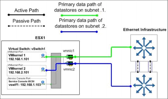
Figure 4-12 VMware ESX Server Switch1 normal operation
Figure 4-13 shows the data flow when a switch is unavailable.

Figure 4-13 VMware ESX Server Switch1 unavailable operation
4.6.3 Network configuration options for the N series storage system
This section examines the networking options from the N series perspective.
Option 1: Storage-side multimode VIFs with LACP
If the switches to be used for IP storage networking support cross-stack EtherChannel trunking, each storage controller only needs one physical connection to each switch. The two ports connected to each storage controller are then combined into one multimode Link Aggregation Control Protocol (LACP) VIF, with IP load balancing enabled. Multiple IP addresses can be assigned to the storage controller using IP address aliases on the VIF.
This option has the following advantages:
•It provides two active connections to each storage controller.
•It easily scales to more connections.
•Storage controller connection load balancing is automatically managed by EtherChannel IP load balancing policy.
This option has the disadvantage that not all switch vendors or switch models support cross-switch EtherChannel trunks.
Figure 4-14 shows how option 1 is configured.

Figure 4-14 Storage-side multimode VIFs using LACP across stacked switches
Option 2: Storage-side single mode VIFs
In this configuration, the IP switches to be used do not support cross-stack trunking. Therefore, each storage controller requires four physical network connections. The connection is divided into two single mode (active/passive) VIFs. Each VIF has a connection to both switches and a single IP address assigned to it. The vif favor command is used to force each VIF to use the appropriate switch for its active interface.
This option has the following advantages:
•No switch-side configuration is required.
•It provides two active connections to each storage controller.
•It scales for more connections.
This option has the disadvantage that it requires two physical connections for each active network connection. Figure 4-15 shows how option 2 is configured.
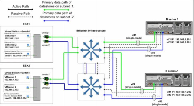
Figure 4-15 Storage-side single mode VIFs
Option 3: Storage-side multimode VIFs
In this configuration, the IP switches to be used do not support cross-stack trunking. Therefore, each storage controller requires four physical network connections. The connections are divided into two multimode (active/active) VIFs with IP load balancing enabled, with one VIF connected to each of the two switches. These two VIFs are then combined into one single mode (active/passive) VIF. Multiple IP addresses can be assigned to the storage controller using IP address aliases on the single mode VIF.
This option has the following advantages:
•It provides two active connections to each storage controller.
•It scales for more connections.
•Storage controller connection load balancing is automatically managed by EtherChannel IP load balancing policy.
This option has the following disadvantages:
•It requires two physical connections for each active network connection.
•Some switch-side configuration is required.
•Some storage traffic can cross the uplink between the two switches.
Figure 4-16 shows how option 3 is configured.
Figure 4-16 Storage-side multimode VIFs
Failover behavior of an N series network connection
This section explores the failure behavior of an N series network connection.
Storage controller connection failure (link failure)
Depending on the N series configuration option used, traffic from the VMware ESX Server is routed through the other switch or to one of the other active connections of the multimode VIF. Traffic returns to the original connection when service to the connection is restored.
Switch failure
Traffic originally running to the failed switch is rerouted and continues through the other available adapter, through the surviving switch, to the N series storage system. Traffic returns to the original adapter when the failed switch is repaired or replaced.
Storage controller failure
The surviving controller services requests to the failed controller after a cluster takeover. All interfaces on the failed controller are automatically started on the surviving controller. Traffic returns to the original controller when it returns to normal operation.
4.7 Increasing storage utilization
VMware provides a means of increasing the hardware utilization of physical servers. By increasing hardware utilization, the amount of hardware in a data center can be reduced, thus lowering the cost of data center operations. In a typical environments, the process of migrating physical servers to virtual machines does not reduce the amount of data stored or the amount of storage provisioned. By default, server virtualization does not have any impact on improving storage utilization, and in many cases might have the opposite effect.
By using deduplication and storage thin provisioning, higher density of storage utilization can be achieved.
Another element to consider is the configuration of transient volumes.
4.7.1 N series deduplication
By providing deduplication options, the N series can provide important benefits to vSphere environments.
Deduplication considerations with VMFS and RDM LUNs
Enabling deduplication when provisioning LUNs produces storage savings. However, the default behavior of a LUN is to reserve an amount of storage equal to the provisioned LUN. This design means that although the storage array reduces the amount of capacity consumed, any gains made with deduplication are usually unrecognizable. This occurs because the space reserved for LUNs is not reduced.
To recognize the storage savings of deduplication with LUNs, you must enable LUN thin provisioning. In addition, although deduplication reduces the amount of consumed storage, this benefit is not seen directly by the VMware ESX Server administrative team. Their view of the storage is at a LUN layer, and as explained earlier, LUNs always represent their provisioned capacity, whether they are traditional or thin provisioned.
Deduplication considerations with NFS
Unlike with LUNs, when deduplication is enabled with NFS, the storage savings are both immediately available and recognized by the VMware ESX Server administrative team. No special considerations are required for its usage.
4.7.2 Storage thin provisioning
You are probably familiar with traditional storage provisioning and the way in which storage is pre-allocated and assigned to VMs. A common practice for server administrators is to over provision storage to avoid running out of storage and the associated application downtime when expanding the provisioned storage. Although no system can be run at 100% storage utilization, storage virtualization methods allow administrators to address and over subscribe storage in the same manner as with server resources, such as CPU, memory, networking, and so on. This form of storage virtualization is referred to as thin provisioning.
Thin provisioning principles
Thin provisioning provides storage on demand, where traditional provisioning pre-allocates storage. The value of thin-provisioned storage is that storage is treated as a shared resource pool and is consumed only as each individual guest requires it. This sharing increases the total utilization rate of storage by eliminating the unused but provisioned areas of storage that are associated with traditional storage. The drawback to thin provisioning and over subscribing storage is that, without the addition of physical storage, if every guest requires its maximum storage at the same time, there is not enough storage to satisfy the requests.
N series thin provisioning options
N series thin provisioning allows LUNs that are serving VMFS datastores to be provisioned to their total capacity limit yet consume only as much storage as is required to store the VMDK files (of either thick or thin format). In addition, LUNs connected as RDMs can be thin provisioned.
4.7.3 Elements of thin provisioning
Thin provisioning can be performed at the volume level and the LUN level. To see the space savings when using N series deduplication on LUNs being presented to VMware hosts, you must enable LUN-level thin provisioning. The space savings using the Network File System (NFS) are immediately available.
Volume-level thin provisioning
Volumes can be set to a space guarantee of Volume, File, or None. By default, volumes are created with a space guarantee of Volume, which pre-allocates the size of the volume within the aggregate. No other application can use it, even if it is empty space.
When you enable the space guarantee to None, you enable volume-level thin provisioning. With volume-level thin provisioning, you can create volumes larger than the size of the aggregate. Also, the space gets allocated when the application writes to it.
A space guarantee of File pre-allocates space in the volume. In this case, any file in the volume with space reservation enabled can be rewritten, even if its blocks are marked for a Snapshot.
LUN-level thin provisioning
During the creation of a LUN, you can select Space Reserved. Alternatively, you can clear the option and enable thin provisioning on the LUN. If you select Space Reserved, the total space of the LUN is pre-allocated in the volume. Even though the space is not being used by the LUN, it is not accessible for use by any other LUN in the volume.
If you clear the Space Reserved option, the unused space in the volume can be claimed by another volume, thus maximizing storage usage.
4.8 Snapshots
This topic provides information about the backup and recovery techniques and technologies that you can use with a VMware vSphere 4.1 and N series solution.
VMware is capable of taking a Snapshot of guests, which enables you to make point-in-time copies that provide the fastest means to recover a guest to a previous point in time. N series storage systems have been providing customers with the ability to create Snapshot copies of their data since its introduction. The basic concept of a Snapshot is similar between N series systems and VMware. However, be aware of the major differences between the two technologies and when to use one rather than the other.
VMware snapshots provide simple point-in-time versions of guests, allowing quick recovery. The benefits of VMware snapshots are the easy way to create and use them, because they can be executed and scheduled from within vCenter.
|
Tip: Do not use the Snapshot technology in VMware as the only way to back up your virtual infrastructure.
|
For more information about native VMware snapshots, including usage guidelines, see the Datacenter Administration Guide at the following website:
The patented N series Snapshot technology can easily be integrated into VMware environments. This technology provides crash-consistent versions of guests for full guest recovery, full guest cloning, or site replication and disaster recovery. The benefits of this solution are that it is the storage industry’s only Snapshot technology that does not have a negative impact on system performance. VMware states that, for optimum performance and scalability, hardware-based Snapshot technology is preferred over software-based solutions. The limitation of this solution is that it is not managed within VMware vCenter, requiring external scripting or scheduling to manage the process.
4.9 N series FlexShare
VMware vSphere 4.1 provides options for memory reservations. These techniques provide administrators the ability to ensure that certain guests, or a group of guests, get the memory needed to achieve the performance required. In a similar fashion, IBM System Storage N series systems provide a workload prioritization method called FlexShare.
FlexShare prioritizes processing resources for key services when the system is under heavy load. FlexShare does not provide guarantees on the availability of resources or how long particular operations take to complete. FlexShare provides a priority mechanism to give preferential treatment to higher priority tasks.
With the use of FlexShare, administrators can confidently consolidate different applications and data sets on a single storage system. FlexShare gives administrators the control to prioritize applications based on how critical they are to the business (Figure 4-17).

Figure 4-17 FlexShare prioritization
FlexShare is supported on N series storage systems running Data ONTAP Version 7.2 and later.
FlexShare provides storage systems with the following key features:
•Relative priority of different volumes
•Per-volume user versus system priority
•Per-volume cache policies
By using these features, storage administrators can set how the system must prioritize resources when the storage is overloaded.
|
Priority settings:
•Before configuring priority on a storage system, you must understand the different workloads on the storage and the impact of setting priorities. Improperly configured priority settings can have undesired effects on application and system performance. The administrator must be well-versed in the configuration implications and best practices.
•For additional information about FlexShare, see IBM System Storage N series with FlexShare, REDP-4291.
|
4.10 Licensing
You can employ numerous advanced features for your virtual data center. Many of these features require you to purchase nothing more than an additional license to activate the feature. This topic addresses the types of licensing.
4.10.1 VMware licensing
VMware provides a free hypervisor, which is the software to enable the “hardware partitioning” to create virtual machines. It is basically an ESXi, which alone does not provide redundancy and resiliency features as vMotion. You can download it at this website:
With the purchase of VMware vCenter, you can enable the following features with the addition of a license key and an additional server, when required:
•VCenter Agent for ESX Server
•VMotion
•VMware High Availability
•VMware Dynamic Resource Scheduling
•VMware Consolidated Backup
•VMware Fault Tolerance.
For additional information about VMware vSphere components and requirements, see this website:
http://www.vmware.com/products/vsphere/overview.html
4.10.2 N series licensing
With the purchase of an IBM System Storage N series system, you can enable features with the addition of a license key. The software licensing structure has been changed with the introduction on the N62xx models. An overview of different licensing options is provided in Figure 4-18.

Figure 4-18 N series software structure
Again, you must ensure that any necessary features for your environment are licensed.
For additional information about N series advanced features and their requirements, see the NAS page at this website:
..................Content has been hidden....................
You can't read the all page of ebook, please click here login for view all page.