

System upgrades
This chapter provides an overview of z14 upgrade capabilities and procedures, with an emphasis on capacity on demand (CoD) offerings. The upgrade offerings to the z14 systems were developed from previous IBM Z servers.
|
Note: Throughout this chapter, “z14” refers to IBM z14 Model M0x (Machine Type 3906) unless otherwise specified.
|
In response to client demands and changes in market requirements, many features were added. The provisioning environment gives you unprecedented flexibility and more control over cost and value.
For more information about all aspects of system upgrades, see the IBM Resource Link website (registration is required). At the website, click Resource Link → Client Initiated Upgrade Information, and then select Education. Select your particular product from the list of available systems.
The growth capabilities that are provided by the z14 servers include the following benefits:
•Enabling the use of new business opportunities
•Supporting the growth of dynamic, smart, and cloud environments
•Managing the risk of volatile, high-growth, and high-volume applications
•Supporting 24 x 7 application availability
•Enabling capacity growth during lockdown periods
•Enabling planned-downtime changes without availability effects
This chapter includes the following topics:
8.1 Upgrade types
The types of upgrades for a z14 server are described in this section.
8.1.1 Overview of upgrade types
Upgrades can be categorized as described in this section.
Permanent and temporary upgrades
Permanent and temporary upgrades are different types of upgrades that can be used in different situations. For example, a growing workload might require more memory, more I/O cards, or more processor capacity. However, only a short-term upgrade might be necessary to handle a peak workload, or to temporarily replace a system that is down during a disaster or data center maintenance. z14 servers offer the following solutions for such situations:
•Permanent:
– Miscellaneous equipment specification (MES):
The MES upgrade order is always performed by IBM personnel. The result can be real hardware or installation of Licensed Internal Code Configuration Control (LICCC) to the system. In both cases, installation is performed by IBM personnel.
– Customer Initiated Upgrade (CIU):
The use of the CIU facility for a system requires that the online CoD buying feature (FC 9900) is installed on the system. The CIU facility supports only LICCC upgrades.
•Temporary:
All temporary upgrades are LICCC-based. The one billable capacity offering is On/Off Capacity on Demand (On/Off CoD). The two replacement capacity offerings available are Capacity Backup (CBU) and Capacity for Planned Event (CPE).
For more information, see 8.1.2, “Terminology that is related to CoD for z14 systems” on page 318.
|
Tip: An MES provides system upgrades that can result in more enabled processors, a different central processor (CP) capacity level, and in more processor drawers, memory, PCIe I/O drawers, and I/O features (physical upgrade). Extra planning tasks are required for nondisruptive logical upgrades. An MES is ordered through your IBM representative and installed by IBM service support representatives (IBM SSRs).
|
Concurrent and nondisruptive upgrades
Depending on the affect on the system and application availability, upgrades can be classified in the following manner:
•Concurrent
In general, concurrency addresses the continuity of operations of the hardware part of an upgrade; for example, whether a system (hardware) is required to be turned off during the upgrade. For more information, see 8.2, “Concurrent upgrades” on page 321.
•Non-concurrent
This type of upgrade requires turning off the hardware that is being upgraded. Examples include model upgrades from any z14 model to the z14 M05 model, and certain physical memory capacity upgrades.
•Disruptive
An upgrade is considered disruptive when resources that are modified or added to an operating system image require that the operating system be restarted to configure the newly added resources.
•Nondisruptive
Nondisruptive upgrades do not require the software or operating system to be restarted for the upgrade to take effect. Therefore, even concurrent upgrades can be disruptive to operating systems or programs that do not support the upgrades while being nondisruptive to others. For more information, see 8.8, “Nondisruptive upgrades” on page 355.
8.1.2 Terminology that is related to CoD for z14 systems
The most frequently used terms that are related to CoD for z14 systems are listed in Table 8-1.
Table 8-1 CoD terminology
|
Term
|
|
Description
|
|
Activated capacity
|
|
Capacity that is purchased and activated. Purchased capacity can be greater than the activated capacity.
|
|
Billable capacity
|
|
Capacity that helps handle workload peaks (expected or unexpected). The one billable offering that is available is On/Off Capacity on Demand (OOCoD).
|
|
Capacity
|
|
Hardware resources (processor and memory) that can process the workload can be added to the system through various capacity offerings.
|
|
Capacity Backup
(CBU) |
|
Capacity Backup allows you to place model capacity or specialty engines in a backup system. CBU is used in an unforeseen loss of system capacity because of an emergency.
|
|
Capacity for Planned Event (CPE)
|
|
Used when temporary replacement capacity is needed for a short-term event. CPE activates processor capacity temporarily to facilitate moving systems between data centers, upgrades, and other routine management tasks. CPE is an offering of CoD.
|
|
Capacity levels
|
|
Can be full capacity or subcapacity. For the z14 system, capacity levels for the CP engine are 7, 6, 5, and 4:
•1 - 99 in decimal and A0 - H0, where A0 represents 100 and H0 represents 170, for capacity level 7nn.
•1 - 33 for capacity levels 6yy and 5yy.
•0 - 33 for capacity levels 4xx. An all Integrated Facility for Linux (IFL) or an all integrated catalog facility (ICF) system has a capacity level of 400.
|
|
Capacity setting
|
|
Derived from the capacity level and the number of processors.
For the z14 system, the capacity levels are 7nn, 6yy, 5yy, and 4xx, where xx, yy, or nn indicates the number of active CPs.
The number of processors can have the following ranges:
•1 - 99 in decimal and A0 - H0, where A0 represents 100 and H0 represents 170, for capacity level 7nn.
•1 - 33 for capacity levels 6yy and 5yy.
•0 - 33 for capacity levels 4xx. An all IFL or an all ICF system has a capacity level of 400.
|
|
Customer Initiated Upgrade (CIU)
|
|
A web-based facility in which you can request processor and memory upgrades by using the IBM Resource Link and the system’s Remote Support Facility (RSF) connection.
|
|
Capacity on Demand (CoD)
|
|
The ability of a computing system to increase or decrease its performance capacity as needed to meet fluctuations in demand.
|
|
Capacity Provisioning Manager (CPM)
|
|
As a component of z/OS Capacity Provisioning, CPM monitors business-critical workloads that are running on z/OS on z14 systems.
|
|
Customer profile
|
|
This information is on Resource Link, and contains client and system information. A customer profile can contain information about more than one system.
|
|
Full capacity CP feature
|
|
For z14 servers, feature (CP7) provides full capacity. Capacity settings 7nn are full capacity settings.
|
|
High-water mark
|
|
Capacity that is purchased and owned by the client.
|
|
Installed record
|
|
The LICCC record is downloaded, staged to the Support Element (SE), and is installed on the central processor complex (CPC). A maximum of eight different records can be concurrently installed and active.
|
|
Model capacity identifier (MCI)
|
|
Shows the current active capacity on the system, including all replacement and billable capacity.
For z14 servers, the model capacity identifier is in the form of 7nn, 6yy, 5yy, or 4xx, where xx, yy, or nn indicates the number of active CPs:
•1 - 99 in decimal and A0 - H0, where A0 represents 100 and H0 represents 170, for capacity level 7nn.
•yy can have a range of 01 - 33.
•xx can have a range of 00 - 33. An all IFL or an all ICF system has a capacity level of 400.
|
|
Model Permanent Capacity Identifier (MPCI)
|
|
Keeps information about the capacity settings that are active before any temporary capacity is activated.
|
|
Model Temporary Capacity Identifier (MTCI)
|
|
Reflects the permanent capacity with billable capacity only, without replacement capacity. If no billable temporary capacity is active, MTCI equals the MPCI.
|
|
On/Off Capacity on Demand (CoD)
|
|
Represents a function that allows spare capacity in a CPC to be made available to increase the total capacity of a CPC. For example, On/Off CoD can be used to acquire more capacity for handling a workload peak.
|
|
Features on Demand (FoD)
|
|
FoD is a new centralized way to entitle flexibly features and functions on the system. On z196 and z114, the HWMs are stored in the processor and memory LICCC record. On z14, z13 and zEC12 servers, the HWMs are stored in the FoD record.
|
|
Permanent capacity
|
|
The capacity that a client purchases and activates. This amount might be less capacity than the total capacity purchased.
|
|
Permanent upgrade
|
|
LIC that is licensed by IBM to enable the activation of applicable computing resources, such as processors or memory, for a specific CIU-eligible system on a permanent basis.
|
|
Purchased capacity
|
|
Capacity that is delivered to and owned by the client. It can be higher than the permanent capacity.
|
|
Permanent/
Temporary entitlement record |
|
The internal representation of a temporary (TER) or permanent (PER) capacity upgrade that is processed by the CIU facility. An entitlement record contains the encrypted representation of the upgrade configuration with the associated time limit conditions.
|
|
Replacement capacity
|
|
A temporary capacity that is used for situations in which processing capacity in other parts of the enterprise is lost. This loss can be a planned event or an unexpected disaster. The two replacement offerings available are Capacity for Planned Events and Capacity Backup.
|
|
Resource Link
|
|
The IBM Resource Link is a technical support website that provides a comprehensive set of tools and resources. It is available at the IBM Systems technical support website.
|
|
Secondary approval
|
|
An option that is selected by the client that requires second approver control for each CoD order. When a secondary approval is required, the request is sent for approval or cancellation to the Resource Link secondary user ID.
|
|
Staged record
|
|
The point when a record that represents a temporary or permanent capacity upgrade is retrieved and loaded on the SE disk.
|
|
Subcapacity
|
|
For z14 servers, CP features (CP4, CP5, and CP6) provide reduced capacity relative to the full capacity CP feature (CP7).
|
|
Temporary capacity
|
|
An optional capacity that is added to the current system capacity for a limited amount of time. It can be capacity that is owned or not owned by the client.
|
|
Vital product data (VPD)
|
|
Information that uniquely defines system, hardware, software, and microcode elements of a processing system.
|
8.1.3 Permanent upgrades
Permanent upgrades can be obtained by using the following processes:
•Ordered through an IBM marketing representative
•Initiated by the client with the CIU on the IBM Resource Link
|
Tip: The use of the CIU facility for a system requires that the online CoD buying feature (FC 9900) is installed on the system. The CIU facility is enabled through the permanent upgrade authorization feature code (FC 9898).
|
Permanent upgrades that are ordered through an IBM representative
Through a permanent upgrade, you can accomplish the following tasks:
•Add processor drawers
•Add Peripheral Component Interconnect Express (PCIe) drawers and features
•Add model capacity
•Add specialty engines
•Add memory
•Activate unassigned model capacity or IFLs
•Deactivate activated model capacity or IFLs
•Activate channels
•Activate cryptographic engines
•Change specialty engine (recharacterization)
|
Considerations: Most of the MESs can be concurrently applied without disrupting the workload. For more information, see 8.2, “Concurrent upgrades” on page 321. However, certain MES changes are disruptive, such as model upgrades from any z14 model to the z14 M05 model.
Memory upgrades that require dual in-line memory module (DIMM) changes can be made nondisruptively multiple CPC drawers are available and the flexible memory option is used.
|
Permanent upgrades by using CIU on the IBM Resource Link
Ordering the following permanent upgrades by using the CIU application through Resource Link allows you to add capacity to fit within your hardware:
•Add model capacity
•Add specialty engines
•Add memory
•Activate unassigned model capacity or IFLs
•Deactivate activated model capacity or IFLs
8.1.4 Temporary upgrades
z14 servers offer the following types of temporary upgrades:
•On/Off Capacity on Demand (On/Off CoD)
This offering allows you to temporarily add more capacity or specialty engines to cover seasonal activities, period-end requirements, peaks in workload, or application testing. This temporary upgrade can be ordered by using the CIU application through Resource Link only.
•CBU
This offering allows you to replace model capacity or specialty engines in a backup system that is used in an unforeseen loss of system capacity because of a disaster.
•CPE
This offering allows you to replace model capacity or specialty engines because of a relocation of workload during system migrations or a data center move.
CBU or CPE temporary upgrades can be ordered by using the CIU application through Resource Link or by calling your IBM marketing representative.
Temporary upgrade capacity changes can be billable or a replacement.
Billable capacity
To handle a peak workload, you can activate up to double the purchased capacity of any processor unit (PU) type temporarily. You are charged daily.
The one billable capacity offering is On/Off Capacity on Demand (On/Off CoD).
Replacement capacity
When a processing capacity is lost in another part of an enterprise, replacement capacity can be activated. It allows you to activate any PU type up to your authorized limit.
The following replacement capacity offerings are available:
•Capacity Backup
•Capacity for Planned Event
8.2 Concurrent upgrades
Concurrent upgrades on z14 servers can provide more capacity with no system outage. In most cases, a concurrent upgrade can be nondisruptive to the operating system with planning and operating system support.
The concurrent capacity growth capabilities that are provided by z14 servers include, but are not limited to, the following benefits:
•Enabling the meeting of new business opportunities
•Supporting the growth of smart and cloud environments
•Managing the risk of volatile, high-growth, and high-volume applications
•Supporting 24 x 7 application availability
•Enabling capacity growth during lockdown or frozen periods
•Enabling planned-downtime changes without affecting availability
This capability is based on the flexibility of the design and structure, which allows concurrent hardware installation and Licensed Internal Code (LIC) control over the configuration.
The subcapacity models allow more configuration granularity within the family. The added granularity is available for models that are configured with up to 33 CPs, and provides 99 extra capacity settings. Subcapacity models provide for CP capacity increase in two dimensions that can be used together to deliver configuration granularity. The first dimension is adding CPs to the configuration. The second is changing the capacity setting of the CPs currently installed to a higher model capacity identifier.
z14 servers allow the concurrent and nondisruptive addition of processors to a running logical partition (LPAR). As a result, you can have a flexible infrastructure in which you can add capacity without pre-planning. This function is supported by z/OS, z/VM, and z/VSE. This addition is made by using one of the following methods:
•With planning ahead for the future need of extra processors. Reserved processors can be specified in the LPAR’s profile. When the extra processors are installed, the number of active processors for that LPAR can be increased without the need for a partition reactivation and initial program load (IPL).
•Another (easier) way is to enable the dynamic addition of processors through the z/OS LOADxx member. Set the DYNCPADD parameter in member LOADxx to ENABLE. z14 servers support dynamic processor addition in the same way that the z13, zEC12, z196, and z10 support it. The operating system must be z/OS V1R10 or later.
Another function concerns the system assist processor (SAP). When more SAPs are concurrently added to the configuration, the SAP-to-channel affinity is dynamically remapped on all SAPs on the system to rebalance the I/O configuration.
8.2.1 Model upgrades
z14 servers feature the following machine type and model, and model capacity identifiers:
•Machine type and model 3906-Mvv
The vv can be 01, 02, 03, 04, or 05. The model number indicates how processor drawers are installed:
– Model M01 (one installed processor drawer) can have maximum 33 PUs for client characterization
– M02 (two processor drawers) can have maximum 69
– M03 (three processor drawers) can have maximum A5, which stands for 105, where A5 stands for 105
– M04 (four processor drawers) can have E5, which stands for 145
– Model M05 (four processor drawers) can have H0, which stands for 170, where H0 stands for 170
•Model capacity identifiers 4xx, 5yy, 6yy, or 7nn
The xx is a range of 00 - 331, yy is a range of 01 - 33, and nn is a range of 01 - 99, A0 - H0, where A0 represents the decimal number 100, which combines the hexadecimal A with decimal 0 and H0 represents the decimal number 170. It is obtained by continuing the hexadecimal counting to F that equals 15, G equals 16, and H equals 17 and adding the decimal digit 0 to make 170. A z14 server with 170 client usable processors is a z14 7H0. The model capacity identifier describes how many CPs are characterized (xx, yy, or nn) and the capacity setting (4, 5, 6, or 7) of the CPs.
A hardware configuration upgrade always requires more physical hardware (processor drawers, PCIe I/O drawers, or both). A system upgrade can change either, or both, of the system model and the MCI.
Consider the following points regarding model upgrades:
•LICCC upgrade:
– Does not change the system model 3906-M0v because more processor drawers are not added
– Can change the model capacity identifier, the capacity setting, or both
•Hardware installation upgrade:
– Can change the system model 3906-M0v if one or more processor drawers are added
– Can change the model capacity identifier, the capacity setting, or both
The system model and the model capacity identifier can be concurrently changed. Concurrent upgrades can be performed for permanent and temporary upgrades.
|
Tip: A model upgrade can be performed concurrently by using concurrent drawer add (CDA), except for upgrades to Model M05, which are included only.
|
Licensed Internal Code upgrades (MES ordered)
The LICCC provides for system upgrades without hardware changes by activating extra (previously installed) unused capacity. Concurrent upgrades through LICCC can be performed for the following resources:
•Processors, such as CPs, ICFs, IBM z Integrated Information Processors (zIIPs), IFLs, and SAPs, if unused PUs are available on the installed processor drawers, or if the model capacity identifier for the CPs can be increased.
•Memory, when unused capacity is available on the installed memory cards. Plan-ahead memory and the flexible memory option are available to give you better control over future memory upgrades. For more information, see 2.4.7, “Flexible Memory Option” on page 63, and 2.4.8, “Pre-planned memory” on page 63.
Concurrent hardware installation upgrades (MES ordered)
Configuration upgrades can be concurrent when installing the following resources:
•Processor drawers (which contain processors, memory, and fanouts). Up to three processor drawers can be added concurrently on the model z14 M01.
•PCIe fanouts.
•I/O cards, when slots are still available on the installed PCIe I/O drawers.
•PCIe I/O drawers.
The concurrent I/O upgrade capability can be better used if a future target configuration is considered during the initial configuration.
Concurrent PU conversions (MES ordered)
z14 servers support concurrent conversion between all PU types, which includes SAPs, to provide flexibility to meet changing business requirements.
|
Important: The LICCC-based PU conversions require that at least one PU (CP, ICF, or IFL), remains unchanged. Otherwise, the conversion is disruptive. The PU conversion generates an LICCC that can be installed concurrently in two steps:
1. Remove the assigned PU from the configuration.
2. Activate the newly available PU as the new PU type.
|
LPARs also might have to free the PUs to be converted. The operating systems must include support to configure processors offline or online so that the PU conversion can be done nondisruptively.
|
Considerations: Client planning and operator action are required to use concurrent PU conversion. Consider the following points about PU conversion:
•It is disruptive if all current PUs are converted to different types.
•It might require individual LPAR outages if dedicated PUs are converted.
Unassigned CP capacity is recorded by a model capacity identifier. CP feature conversions change (increase or decrease) the model capacity identifier.
|
8.2.2 Customer Initiated Upgrade facility
The CIU facility is an IBM online system through which you can order, download, and install permanent and temporary upgrades for IBM Z servers. Access to and use of the CIU facility requires a contract between the client and IBM through which the terms and conditions for use of the CIU facility are accepted.
The use of the CIU facility for a system requires that the online CoD buying feature code (FC 9900) is installed on the system. Although it can be installed on your z14 servers at any time, often it is added when ordering a z14 server. The CIU facility is controlled through the permanent upgrade authorization feature code, FC 9898.
After you place an order through the CIU facility, you receive a notice that the order is ready for download. You can then download and apply the upgrade by using functions that are available through the Hardware Management Console (HMC), along with the RSF. After all of the prerequisites are met, the entire process, from ordering to activation of the upgrade, is performed by the client.
After download, the actual upgrade process is fully automated and does not require any onsite presence of IBM SSRs.
CIU prerequisites
The CIU facility supports LICCC upgrades only. It does not support I/O upgrades. All other capacity that is required for an upgrade must be previously installed. Extra processor drawers or I/O cards cannot be installed as part of an order that is placed through the CIU facility. The sum of CPs, unassigned CPs, ICFs, zIIPs, IFLs, and unassigned IFLs cannot exceed the client (characterized) PU count of the installed processor drawers. The total number of zIIPs can be twice the number of purchased CPs.
CIU registration and contract for CIU
To use the CIU facility, a client must be registered and the system must be set up. After you complete the CIU registration, access to the CIU application is available through the IBM Resource Link website.
As part of the setup, provide one resource link ID for configuring and placing CIU orders and, if required, a second ID as an approver. The IDs are then set up for access to the CIU support. The CIU facility allows upgrades to be ordered and delivered much faster than through the regular MES process.
To order and activate the upgrade, log on to the IBM Resource Link website and start the CIU application to upgrade a system for processors or memory. You can request a client order approval to conform to your operational policies. You also can allow the definition of more IDs to be authorized to access the CIU. More IDs can be authorized to enter or approve CIU orders, or only view orders.
Permanent upgrades
Permanent upgrades can be ordered by using the CIU facility. Through the CIU facility, you can generate online permanent upgrade orders to concurrently add processors (CPs, ICFs, zIIPs, IFLs, and SAPs) and memory, or change the model capacity identifier. You can do so up to the limits of the installed processor drawers on a system.
Temporary upgrades
The base model z14 server describes permanent and dormant capacity by using the capacity marker and the number of PU features that are installed on the system. Up to eight temporary offerings can be present. Each offering includes its own policies and controls, and each can be activated or deactivated independently in any sequence and combination. Although multiple offerings can be active at any time, only one On/Off CoD offering can be active at any time if enough resources are available to fulfill the offering specifications.
Temporary upgrades are represented in the system by a record. All temporary upgrade records are on the SE hard disk drive (HDD). The records can be downloaded from the RSF or installed from portable media. At the time of activation, you can control everything locally.
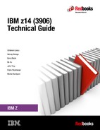
The provisioning architecture is shown in Figure 8-1.

Figure 8-1 Provisioning architecture
The authorization layer enables administrative control over the temporary offerings. The activation and deactivation can be driven manually or under the control of an application through a documented application programming interface (API).
By using the API approach, you can customize at activation time the resources that are necessary to respond to the current situation, up to the maximum that is specified in the order record. If the situation changes, you can add or remove resources without having to go back to the base configuration. This process eliminates the need for temporary upgrade specifications for all possible scenarios. However, the ordered configuration is the only possible activation for CPE.
This approach also enables you to update and replenish temporary upgrades, even in situations where the upgrades are active. Likewise, depending on the configuration, permanent upgrades can be performed while temporary upgrades are active. Examples of the activation sequence of multiple temporary upgrades are shown in Figure 8-2.

Figure 8-2 Example of temporary upgrade activation sequence
As shown in Figure 8-2, if R2, R3, and R1 are active at the same time, only parts of R1 can be activated because not enough resources are available to fulfill all of R1. When R2 is deactivated, the remaining parts of R1 can be activated as shown.
Temporary capacity can be billable as On/Off CoD, or replacement capacity as CBU or CPE. Consider the following points:
•On/Off CoD is a function that enables concurrent and temporary capacity growth of the system.
On/Off CoD can be used for client peak workload requirements, for any length of time, and includes a daily hardware and maintenance charge. The software charges can vary according to the license agreement for the individual products. For more information, contact your IBM Software Group representative.
On/Off CoD can concurrently add processors (CPs, ICFs, zIIPs, IFLs, and SAPs), increase the model capacity identifier, or both. It can do so up to the limit of the installed processor drawers of a system. It is restricted to twice the installed capacity. On/Off CoD requires a contractual agreement between you and IBM.
You decide whether to pre-pay or post-pay On/Off CoD. Capacity tokens that are inside the records are used to control activation time and resources.
•CBU is a concurrent and temporary activation of more CPs, ICFs, zIIPs, IFLs, and SAPs, an increase of the model capacity identifier, or both.
CBU cannot be used for peak workload management in any form. As stated, On/Off CoD is the correct method to use for workload management. A CBU activation can last up to 90 days when a disaster or recovery situation occurs.
CBU features are optional, and require unused capacity to be available on installed processor drawers of the backup system. They can be available as unused PUs, an increase in the model capacity identifier, or both.
A CBU contract must be in place before the special code that enables this capability can be loaded on the system. The standard CBU contract provides for five 10-day tests2 (the CBU test activation) and one 90-day activation over a five-year period. For more information, contact your IBM representative.
You can run production workload on a CBU upgrade during a CBU test. At least an equivalent amount of production capacity must be shut down during the CBU test. If you signed CBU contracts, you also must sign an Amendment (US form #Z125-8145) with IBM to allow you to run production workload on a CBU upgrade during your CBU tests.
•CPE is a concurrent and temporary activation of extra CPs, ICFs, zIIPs, IFLs, and SAPs, an increase of the model capacity identifier, or both.
The CPE offering is used to replace temporary lost capacity within a client’s enterprise for planned downtime events, such as data center changes. CPE cannot be used for peak load management of client workload or for a disaster situation.
The CPE feature requires unused capacity to be available on installed processor drawers of the backup system. The capacity must be available as unused PUs, as a possibility to increase the model capacity identifier on a subcapacity system, or as both.
A CPE contract must be in place before the special code that enables this capability can be loaded on the system. The standard CPE contract provides for one 3-day planned activation at a specific date. For more information, contact your IBM representative.
8.2.3 Concurrent upgrade functions summary
The possible concurrent upgrades combinations are listed in Table 8-2.
Table 8-2 Concurrent upgrade summary
|
Type
|
Name
|
Upgrade
|
Process
|
|
Permanent
|
MES
|
CPs, ICFs, zIIPs, IFLs, SAPs, processor drawer, memory, and I/Os
|
Installed by IBM SSRs
|
|
Online permanent upgrade
|
CPs, ICFs, zIIPs, IFLs, SAPs, and memory
|
Performed through the CIU facility
|
|
|
Temporary
|
On/Off CoD
|
CPs, ICFs, zIIPs, IFLs, and SAPs
|
Performed through the OOCoD facility
|
|
CBU
|
CPs, ICFs, zIIPs, IFLs, and SAPs
|
Performed through the CBU facility
|
|
|
CPE
|
CPs, ICFs, zIIPs, IFLs, and SAPs
|
Performed through the CPE facility
|
8.3 Miscellaneous equipment specification upgrades
MES upgrades enable concurrent and permanent capacity growth. MES upgrades allow the concurrent adding of processors (CPs, ICFs, zIIPs, IFLs, and SAPs), memory capacity, and I/O ports. For subcapacity models, MES upgrades allow the concurrent adjustment of both the number of processors and the capacity level. The MES upgrade can be performed by using LICCC only, by installing more processor drawers, by adding PCIe I/O drawers, by adding I/O3 features, or by using the following combinations:
•MES upgrades for processors are done by any of the following methods:
– LICCC assigning and activating unassigned PUs up to the limit of the installed processor drawers.
– LICCC to adjust the number and types of PUs, to change the capacity setting, or both.
– Installing more processor drawers, and LICCC assigning and activating unassigned PUs on the installed processor drawers.
•MES upgrades for memory are done by one of the following methods:
– By using LICCC to activate more memory capacity up to the limit of the memory cards on the currently installed processor drawers. Plan-ahead and flexible memory features enable you to implement better control over future memory upgrades. For more information about the memory features, see the following resources:
– Installing more processor drawers and the use of LICCC to activate more memory capacity on installed processor drawers.
– By using the CPC Enhanced Drawer Availability (EDA), where possible, on multi-drawer systems to add or change the memory cards.
•MES upgrades for I/O5 are done by installing more I/O5 features and supporting infrastructure (if required) on PCIe drawers that are installed, or installing more PCIe drawers to hold the new cards.
An MES upgrade requires IBM SSRs for the installation. In most cases, the time that is required for installing the LICCC and completing the upgrade is short.
To better use the MES upgrade function, carefully plan the initial configuration to allow a concurrent upgrade to a target configuration. The availability of PCIe I/O drawers improves the flexibility to perform unplanned I/O configuration changes concurrently.
The Store System Information (STSI) instruction gives more useful and detailed information about the base configuration and temporary upgrades. You can more easily resolve billing situations where independent software vendor (ISV) products are used.
The model and model capacity identifiers that are returned by the STSI instruction are updated to coincide with the upgrade. For more information, see “Store System Information instruction” on page 358.
|
Upgrades: The MES provides the physical upgrade, which results in more enabled processors, different capacity settings for the CPs, and more memory, I/O ports, I/O adapters, and I/O drawers. Extra planning tasks are required for nondisruptive logical upgrades. For more information, see “Guidelines to avoid disruptive upgrades” on page 360.
|
8.3.1 MES upgrade for processors
An MES upgrade for processors can concurrently add CPs, ICFs, zIIPs, IFLs, and SAPs to a z14 server by assigning available PUs on the processor drawers through LICCC. Depending on the quantity of the extra processors in the upgrade, more processor drawers might be required, and can be concurrently installed before the LICCC is enabled. With the subcapacity models, more capacity can be provided by adding CPs, changing the capacity identifier on the current CPs, or both.
|
Limits: The sum of CPs, inactive CPs, ICFs, zIIPs, IFLs, unassigned IFLs, and SAPs cannot exceed the maximum limit of PUs available for client use. The number of zIIPs cannot exceed twice the number of purchased CPs.
|
An example of an MES upgrade for processors (with two upgrade steps) is shown in Figure 8-3.

Figure 8-3 MES for processor example
A model M01 (one processor drawer), model capacity identifier 708 (eight CPs), is concurrently upgraded to a model M02 (two processor drawers), with MCI 738 (38 CPs). The model upgrade requires adding a processor drawer and assigning and activating 38 PUs as CPs. Then, model M02, MCI 738, is concurrently upgraded to a capacity identifier 739 (39 CPs) with two IFLs. This process is done by assigning and activating three more unassigned PUs (one as CP and two as IFLs). If needed, more LPARs can be created concurrently to use the newly added processors.
The example that is shown in Figure 8-3 was used to show how the addition of PUs as CPs and IFLs and the addition of a processor drawer works. In reality, the addition of a processor drawer to a z14 Model M01 upgrades the machine model to M02.
Also, one of the two spare PUs on CPC drawer 0 is moved over to CPC drawer 1 to have one spare PU on each CPC drawer. After the second CPC drawer addition, CPC drawer 0 has 33 configurable PUs and CPC drawer 1 has 33 configurable PUs, which allow 66 PUs to be characterized on the new M02 model.
|
Consideration: Up to 170 logical processors (including reserved processors) can be defined to an LPAR. However, do not define more processors to an LPAR than the target operating system supports.
|
The number of processors that are supported by various z/OS and z/VM releases are listed in Table 8-3.
Table 8-3 Number of processors that are supported by the operating system
|
Operating system
|
Number of processors that are supported
|
|
z/OS V1R13 with PTFs
|
100
|
|
z/OS V2R1
|
170 PUs per z/OS LPAR in non-SMT mode and 128 PUs per z/OS LPAR in simultaneous multithreading (SMT) mode. For both, the PU total is the sum of CPs and zIIPs.
|
|
z/OS V2R2
|
170 PUs per z/OS LPAR in non-SMT mode and 128 PUs per z/OS LPAR in SMT mode. For both, the PU total is the sum of CPs and zIIPs.
|
|
z/OS V2R3
|
170 PUs per z/OS LPAR in non-SMT mode and 128 PUs per z/OS LPAR in SMT mode. For both, the PU total is the sum of CPs and zIIPs.
|
|
z/VM V7R1
|
641
|
|
z/VM V6R4
|
64a
|
|
z/VSE
|
z/VSE Turbo Dispatcher can use up to 4 CPs, and tolerates up to 10-way LPARs.
|
|
z/TPF
|
86 CPs
|
|
Linux on IBM Z -170 CPs
|
SLES12/RHEL7/Ubuntu 16.10, Linux supports 256 cores without SMT and 128 cores with SMT (256 threads).
|
1 32 in SMT mode
Software charges, which are based on the total capacity of the system on which the software is installed, are adjusted to the new capacity after the MES upgrade.
Software products that use Workload License Charges (WLC) might not be affected by the system upgrade. Their charges are based on partition usage, not on the system total capacity. For more information about WLC, see 7.8, “Software licensing” on page 312.
8.3.2 MES upgrades for memory
MES upgrades for memory can concurrently add more memory in the following ways:
•Through LICCC, enabling more capacity up to the limit of the currently installed DIMM memory cards
•Concurrently installing more CPC drawers and LICCC-enabling memory capacity on the new CPC drawers.
The Preplanned Memory Feature is available to allow better control over future memory upgrades. For more information about plan-ahead memory features, see 2.4.7, “Flexible Memory Option” on page 63 and 2.4.8, “Pre-planned memory” on page 63.
If the z14 server is a multiple processor drawer configuration, you can use the EDA feature to remove a processor drawer and add DIMM memory cards. It can also be used to upgrade the installed memory cards to a larger capacity size. You can then use LICCC to enable the extra memory.
With proper planning, more memory can be added nondisruptively to z/OS partitions and z/VM partitions. If necessary, new LPARs can be created nondisruptively to use the newly added memory.
|
Concurrency: Upgrades that require DIMM changes can be concurrent by using the EDA feature. Planning is required to see whether this option is a viable for your configuration. The use of the flexible memory option and the Preplanned Memory Feature (FC 1996 for the 16-GB increment, or FC 1990 for the 32-GB increment) ensures that EBA can work with the least disruption.
|
The one-processor drawer model M01 features a minimum of 320 GB physically installed memory. The client addressable storage in this case is 256 GB. If you require more memory, an extra memory upgrade can install up to 8 TB of memory. It does so by changing the DIMM sizes and adding DIMMs in all available slots in the processor drawer. You can also add memory by concurrently adding a second processor drawer with sufficient memory into the configuration and then using LICCC to enable that memory.
An LPAR can dynamically take advantage of a memory upgrade if reserved storage is defined to that LPAR. The reserved storage is defined to the LPAR as part of the image profile. Reserved memory can be configured online to the LPAR by using the LPAR dynamic storage reconfiguration (DSR) function. DSR allows a z/OS operating system image and z/VM partitions to add reserved storage to their configuration if any unused storage exists.
The nondisruptive addition of storage to a z/OS and z/VM partition requires that pertinent operating system parameters were prepared. If reserved storage is not defined to the LPAR, the LPAR must be deactivated, the image profile changed, and the LPAR reactivated. This process allows the extra storage resources to be available to the operating system image.
8.3.3 MES upgrades for I/O
MES upgrades for I/O can concurrently add more I/O features by using one of the following methods:
•Installing more I/O features on an installed PCIe I/O drawer.
•Using the installed PCIe I/O drawer that provides the number of I/O slots that are required by the target configuration.
•Adding a PCIe I/O drawer to hold the new I/O features.
For more information about I/O drawers and PCIe I/O drawers, see 4.2, “I/O system overview” on page 147.
The number of I/O drawers and PCIe I/O drawers that can be present in a z14 server are listed in Table 8-4 on page 333.
Table 8-4 I/O drawers and PCIe drawer summary
|
Description
|
New build
|
Carry-forward
|
MES add
|
|
PCIe I/O drawer
|
0 - 5
|
0 - 51
|
0 - 5
|
1 New PCIe I/O Drawers are delivered in an upgrade from zEC12.
Depending on the number of I/O features that are carried forward on an upgrade, the configurator determines the number of PCIe I/O drawers.
To better use the MES for I/O capability, carefully plan the initial configuration to allow concurrent upgrades up to the target configuration. If original I/O features are removed from the I/O drawer, the configurator does not physically remove the drawer unless the I/O frame slots are required to install a new PCIe I/O drawer.
If a PCIe I/O drawer is added to a z14 server and original features must be physically moved to another PCIe I/O drawer, original card moves are disruptive.
z/VSE, z/TPF, Linux on Z, and CFCC do not provide dynamic I/O configuration support. Although installing the new hardware is done concurrently, defining the new hardware to these operating systems requires an IPL.
|
Tip: z14 servers feature a hardware system area (HSA) of 192 GB. z13 servers have a 96 GB HSA. HSA is not part of the client-purchased memory.
|
8.3.4 Feature on Demand
Only one FoD LICCC record is installed or staged at any time in the system and its contents can be viewed under the Manage window, as shown in Figure 8-4.

Figure 8-4 Features on-Demand
A staged record can be removed without installing it. An FoD record can be installed only completely; no selective feature or partial record installation is available. The features that are installed are merged with the CPC LICCC after activation.
An FoD record can be installed only once. If it is removed, a new FoD record is needed to reinstall. A remove action cannot be undone.
8.3.5 Summary of plan-ahead features
The following plan-ahead features are available for z14 servers:
•Flexible memory
Flexible memory has no feature code (FC) associated with it. The purpose of flexible memory is to enable enhanced processor drawer availability. If a processor drawer must be serviced, the flexible memory is activated to accommodate storing the CPC drawer that is taken offline. After the repair action, the memory is taken offline again and is made unavailable for use.
•Pre-planned memory
Pre-planned memory allows you to plan for nondisruptive memory upgrades. Any hardware that is required is pre-plugged, based on a target capacity that is specified in advance. Pre-plugged hardware is enabled by using an LICCC order when more memory capacity is needed. FC 1990 provides 32 GB of pre-planned memory, and FC 1991 provides 64 GB of pre-planned memory, and 1999 provides 64 GB of VFM pre-planned memory. The feature codes that are required to activate previously installed pre-planned memory are listed in Table 8-5.
Table 8-5 Feature codes for pre-planned memory activation
|
FC
|
Capacity increment (GB)
|
Notes
|
|
1894
|
256
|
N/A
|
|
1893
|
64
|
N/A
|
|
1898
|
32
|
N/A
|
|
1938
|
256
|
>= 1 TB
|
|
1939
|
64
|
>= 1 TB
|
|
1940
|
32
|
>= 1 TB
|
•Balanced Power Plan Ahead
Balanced Power Plan Ahead is designed to anticipate future upgrade power needs on z14 servers. When more processor drawers are added to the system, the power consumption also rises. If necessary, one or more bulk power regulators (BPRs) must be added. This process increases the time that is needed for the upgrade. When ordering this feature, all six BPR pairs are installed and activated regardless of the configuration. Balanced Power Plan Ahead includes FC 3003.
•Line Cord plan ahead
This option allows you to plan ahead for the second set of power cords. It is normally not configured until the addition of extra BPRs requires them. A plan-ahead option allows you to plan for a lengthy outage that is caused by installing circuit breakers or power feeds, or routing cables under the floor. The Line Cord plan-ahead option is FC 2000.
|
Tip: Accurate planning and the definition of the target configuration allows you to maximize the value of these plan-ahead features.
|
8.4 Permanent upgrade through the CIU facility
By using the CIU facility (through the IBM Resource Link), you can start a permanent upgrade for CPs, ICFs, zIIPs, IFLs, SAPs, or memory. When performed through the CIU facility, you add the resources without the need to have IBM personnel present at your location. You can also unassign previously purchased CPs and IFL processors through the CIU facility.
Adding permanent upgrades to a system through the CIU facility requires that the permanent upgrade enablement feature (FC 9898) is installed on the system. A permanent upgrade might change the system model capacity identifier (4xx, 5yy, 6yy, or 7nn) if more CPs are requested, or if the capacity identifier is changed as part of the permanent upgrade. However, it cannot change the system model. If necessary, more LPARs can be created concurrently to use the newly added processors.
|
Consideration: A permanent upgrade of processors can provide a physical concurrent upgrade, which results in more enabled processors that are available to a system configuration. Therefore, more planning and tasks are required for nondisruptive logical upgrades. For more information, see “Guidelines to avoid disruptive upgrades” on page 360.
|
Maintenance charges are automatically adjusted as a result of a permanent upgrade.
Software charges that are based on the total capacity of the system on which the software is installed are adjusted to the new capacity after the permanent upgrade is installed. Software products that use WLC might not be affected by the system upgrade because their charges are based on an LPAR usage rather than system total capacity. For more information about WLC, see 7.8, “Software licensing” on page 312.
The CIU facility process on IBM Resource Link is shown in Figure 8-5.

Figure 8-5 Permanent upgrade order example
The following sample sequence shows how to start an order on the IBM Resource Link:
1. Sign on to Resource Link.
2. Select Customer Initiated Upgrade from the main Resource Link page. Client and system information that is associated with the user ID are displayed.
3. Select the system to receive the upgrade. The current configuration (PU allocation and memory) is shown for the selected system.
4. Select Order Permanent Upgrade. The Resource Link limits the options to those options that are valid or possible for the selected configuration (system).
5. After the target configuration is verified by the system, accept or cancel the order. An order is created and verified against the pre-established agreement.
6. Accept or reject the price that is quoted. A secondary order approval is optional. Upon confirmation, the order is processed. The LICCC for the upgrade is available within hours.
The order activation process for a permanent upgrade is shown in Figure 8-6. When the LICCC is passed to the Remote Support Facility, you are notified through an email that the upgrade is ready to be downloaded.

Figure 8-6 CIU-eligible order activation example
8.4.1 Ordering
Resource Link provides the interface that enables you to order a concurrent upgrade for a system. You can create, cancel, or view the order, and view the history of orders that were placed through this interface.
Configuration rules enforce that only valid configurations are generated within the limits of the individual system. Warning messages are issued if you select invalid upgrade options. The process allows only one permanent CIU-eligible order for each system to be placed at a time.
For more information, see the Resource Link website.
The initial view of the Machine profile on Resource Link is shown in Figure 8-7.

Figure 8-7 Machine profile window
The number of CPs, ICFs, zIIPs, IFLs, SAPs, memory size, and unassigned IFLs on the current configuration are displayed on the left side of the page.
Resource Link retrieves and stores relevant data that is associated with the processor configuration, such as the number of CPs and installed memory cards. It allows you to select only those upgrade options that are deemed valid by the order process. It also allows upgrades only within the bounds of the currently installed hardware.
8.4.2 Retrieval and activation
After an order is placed and processed, the appropriate upgrade record is passed to the IBM support system for download.
When the order is available for download, you receive an email that contains an activation number. You can then retrieve the order by using the Perform Model Conversion task from the SE, or through the Single Object Operation to the SE from an HMC.
In the Perform Model Conversion window, select Permanent upgrades to start the process, as shown in Figure 8-8.

Figure 8-8 z14 Perform Model Conversion window
The window provides several possible options. If you select the Retrieve and apply data option, you are prompted to enter the order activation number to start the permanent upgrade, as shown in Figure 8-9.

Figure 8-9 Customer Initiated Upgrade Order Activation Number window
8.5 On/Off Capacity on Demand
On/Off CoD allows you to enable temporarily PUs and unassigned IFLs that are available within the current hardware model. You can also use it to change capacity settings for CPs to help meet your peak workload requirements.
8.5.1 Overview
The capacity for CPs is expressed in millions of service units (MSUs). Capacity for speciality engines is expressed in number of speciality engines. Capacity tokens are used to limit the resource consumption for all types of processor capacity.
Capacity tokens are introduced to provide better control over resource consumption when On/Off CoD offerings are activated. Tokens represent the following resource consumptions:
•For CP capacity, each token represents the amount of CP capacity that results in one MSU of software cost for one day (an MSU-day token).
•For speciality engines, each token is equivalent to one speciality engine capacity for one day (an engine-day token).
Each speciality engine type features its own tokens, and each On/Off CoD record includes separate token pools for each capacity type. During the ordering sessions on Resource Link, select how many tokens of each type to create for an offering record. Each engine type must include tokens for that engine type to be activated. Capacity that has no tokens cannot be activated.
When resources from an On/Off CoD offering record that contains capacity tokens are activated, a billing window is started. A billing window is always 24 hours. Billing occurs at the end of each billing window.
The resources that are billed are the highest resource usage inside each billing window for each capacity type. An activation period is one or more complete billing windows. The activation period is the time from the first activation of resources in a record until the end of the billing window in which the last resource in a record is deactivated.
At the end of each billing window, the tokens are decremented by the highest usage of each resource during the billing window. If any resource in a record does not have enough tokens to cover usage for the next billing window, the entire record is deactivated.
|
Note: On/Off CoD requires that the Online CoD Buying feature (FC 9900) is installed on the system that you want to upgrade.
|
The On/Off CoD to Permanent Upgrade Option is a new offering. It is an offshoot of On/Off CoD that takes advantage of aspects of the architecture. You are given a window of opportunity to assess capacity additions to your permanent configurations by using On/Off CoD. If a purchase is made, the hardware On/Off CoD charges during this window (three days or less) are waived. If no purchase is made, you are charged for the temporary use.
The resources eligible for temporary use are CPs, ICFs, zIIPs, IFLs, and SAPs. The temporary addition of memory and I/O ports or adapters is not supported.
Unassigned PUs that are on the installed processor drawers can be temporarily and concurrently activated as CPs, ICFs, zIIPs, IFLs, and SAPs through LICCC. You can assign PUs up to twice the currently installed CP capacity, and up to twice the number of ICFs, zIIPs, or IFLs. Therefore, an On/Off CoD upgrade cannot change the system model. The addition of new processor drawers is not supported. However, the activation of an On/Off CoD upgrade can increase the model capacity identifier (4xx, 5yy, 6yy, or 7nn).
8.5.2 Capacity Provisioning Manager
The installation of the capacity provision function on z/OS requires the following prerequisites:
•Setting up and customizing z/OS RMF, including the Distributed Data Server (DDS).
•Setting up the z/OS CIM Server (included in z/OS base).
•Performing capacity provisioning customization. For more information, see z/OS MVS Capacity Provisioning User’s Guide, SA33-8299.
Using the capacity provisioning function requires the following prerequisites:
•TCP/IP connectivity to observed systems.
•RMF Distributed Data Server must be active.
•CIM server must be active.
•Security and CIM customization.
•Capacity Provisioning Manager customization.
In addition, the Capacity Provisioning Control Center must be downloaded from the host and installed on a PC server. This application is used only to define policies. It is not required for regular operation.
Customizing the capacity provisioning function is required on the following systems:
•Observed z/OS systems
These systems are in one or multiple sysplexes that are to be monitored. For more information about the capacity provisioning domain, see 8.8, “Nondisruptive upgrades” on page 355.
•Runtime systems
These systems are the systems where the Capacity Provisioning Manager is running, or to which the server can fail over after server or system failures.
8.5.3 Ordering
Concurrently installing temporary capacity by ordering On/Off CoD is possible in the following manner:
•CP features equal to the MSU capacity of installed CPs
•IFL features up to the number of installed IFLs
•ICF features up to the number of installed ICFs
•zIIP features up to the number of installed zIIPs
•Up to 5 SAPs for model M01, 10 for an M02, 15 for an M03, and 20 for an M04 and 23 for an M05
On/Off CoD can provide CP temporary capacity in two ways:
•By increasing the number of CPs.
•For subcapacity models, capacity can be added by increasing the number of CPs, changing the capacity setting of the CPs, or both. The capacity setting for all CPs must be the same. If the On/Off CoD is adding CP resources that have a capacity setting different from the installed CPs, the base capacity settings are changed to match.
On/Off CoD includes the following limits that are associated with its use:
– The number of CPs cannot be reduced.
– The target configuration capacity is limited to these amounts:
• Twice the currently installed capacity, expressed in MSUs for CPs.
• Twice the number of installed IFLs, ICFs, and zIIPs. The number of SAPs that can be activated depends on the model. For more information, see 8.2.1, “Model upgrades” on page 322.
On/Off CoD can be ordered as prepaid or postpaid. A prepaid On/Off CoD offering record contains resource descriptions, MSUs, several speciality engines, and tokens that describe the total capacity that can be used. For CP capacity, the token contains MSU-days. For speciality engines, the token contains speciality engine-days.
When resources on a prepaid offering are activated, they must have enough capacity tokens to allow the activation for an entire billing window, which is 24 hours. The resources remain active until you deactivate them or until one resource consumes all of its capacity tokens. Then, all activated resources from the record are deactivated.
A postpaid On/Off CoD offering record contains resource descriptions, MSUs, speciality engines, and can contain capacity tokens that denote MSU-days and speciality engine-days.
When resources in a postpaid offering record without capacity tokens are activated, those resources remain active until they are deactivated, or until the offering record expires. The record usually expires 180 days after its installation.
When resources in a postpaid offering record with capacity tokens are activated, those resources must have enough capacity tokens to allow the activation for an entire billing window (24 hours). The resources remain active until they are deactivated, until all of the resource tokens are consumed, or until the record expires. The record usually expires 180 days after its installation. If one capacity token type is consumed, resources from the entire record are deactivated.
For example, for a z14 server with capacity identifier 502 (two CPs), a capacity upgrade through On/Off CoD can be delivered in the following ways:
•Add CPs of the same capacity setting. With this option, the model capacity identifier can be changed to a 503, which adds one more CP to make it a 3-way CP. It can also be changed to a 504, which adds two CPs, making it a 4-way CP.
•Change to a different capacity level of the current CPs and change the model capacity identifier to a 602 or 702. The capacity level of the CPs is increased, but no other CPs are added. The 502 also can be temporarily upgraded to a 603, which increases the capacity level and adds another processor. The capacity setting 430 does not have an upgrade path through On/Off CoD.
Use the Large System Performance Reference (LSPR) information to evaluate the capacity requirements according to your workload type. For more information about LSPR data for current IBM processors, see the Large Systems Performance Reference for IBM Z page of the IBM Systems website.
The On/Off CoD hardware capacity is charged on a 24-hour basis. A grace period is granted at the end of the On/Off CoD day. This grace period allows up to an hour after the 24-hour billing period to change the On/Off CoD configuration for the next 24-hour billing period or deactivate the current On/Off CoD configuration. The times when the capacity is activated and deactivated are maintained in the z14 server and sent back to the support systems.
If On/Off capacity is active, On/Off capacity can be added without having to return the system to its original capacity. If the capacity is increased multiple times within a 24-hour period, the charges apply to the highest amount of capacity active in that period.
If more capacity is added from an active record that contains capacity tokens, the systems checks whether the resource has enough capacity to be active for an entire billing window (24 hours). If that criteria is not met, no extra resources are activated from the record.
If necessary, more LPARs can be activated concurrently to use the newly added processor resources.
|
Consideration: On/Off CoD provides a concurrent hardware upgrade, which results in more enabled processors that are available to a system configuration. Extra planning tasks are required for nondisruptive upgrades. For more information, see “Guidelines to avoid disruptive upgrades” on page 360.
|
To participate in this offering, you must accept contractual terms for purchasing capacity through the Resource Link, establish a profile, and install an On/Off CoD enablement feature on the system. Later, you can concurrently install temporary capacity up to the limits in On/Off CoD and use it for up to 180 days.
Monitoring occurs through the system call-home facility. An invoice is generated if the capacity is enabled during the calendar month. You are billed for the use of temporary capacity until the system is returned to the original configuration. Remove the enablement code if the On/Off CoD support is no longer needed.
On/Off CoD orders can be pre-staged in Resource Link to allow multiple optional configurations. The pricing of the orders is done at the time that you order them, and the pricing can vary from quarter to quarter. Staged orders can have different pricing.
When the order is downloaded and activated, the daily costs are based on the pricing at the time of the order. The staged orders do not have to be installed in the order sequence. If a staged order is installed out of sequence and later a higher-priced order is staged, the daily cost is based on the lower price.
Another possibility is to store unlimited On/Off CoD LICCC records on the SE with the same or different capacities, which gives you greater flexibility to enable quickly needed temporary capacity. Each record is easily identified with descriptive names, and you can select from a list of records that can be activated.
Resource Link provides the interface to order a dynamic upgrade for a specific system. You can create, cancel, and view the order. Configuration rules are enforced, and only valid configurations are generated based on the configuration of the individual system. After you complete the prerequisites, orders for the On/Off CoD can be placed. The order process uses the CIU facility on Resource Link.
You can order temporary capacity for CPs, ICFs, zIIPs, IFLs, or SAPs. Memory and channels are not supported on On/Off CoD. The amount of capacity is based on the amount of owned capacity for the different types of resources. An LICCC record is established and staged to Resource Link for this order. After the record is activated, it has no expiration date.
However, an individual record can be activated only once. Subsequent sessions require a new order to be generated, which produces a new LICCC record for that specific order.
Alternatively, you can use an auto-renewal feature to eliminate the need for a manual replenishment of the On/Off CoD order. This feature is implemented in Resource Link, and you must also select this feature in the machine profile, as shown in Figure 8-10.

Figure 8-10 Order On/Off CoD record window
8.5.4 On/Off CoD testing
Each On/Off CoD-enabled system is entitled to one no-charge 24-hour test. No IBM charges are assessed for the test, including charges that are associated with temporary hardware capacity, IBM software, and IBM maintenance. The test can be used to validate the processes to download, stage, install, activate, and deactivate On/Off CoD capacity.
This test can have a maximum duration of 24 hours, which commences upon the activation of any capacity resource that is contained in the On/Off CoD record. Activation levels of capacity can change during the 24-hour test period. The On/Off CoD test automatically stops at the end of the 24-hour period.
You also can perform administrative testing. No capacity is added to the system, but you can test all the procedures and automation for the management of the On/Off CoD facility.
An example of an On/Off CoD order on the Resource Link web page is shown in Figure 8-11.

Figure 8-11 On/Off CoD order example
The example order that is shown in Figure 8-11 is an On/Off CoD order for 0% more CP capacity (system is already at capacity level 7), and for two more ICFs and two more zIIPs. The maximum number of CPs, ICFs, zIIPs, and IFLs is limited by the current number of available unused PUs of the installed processor drawers. The maximum number of SAPs is determined by the model number and the number of available PUs on the already installed processor drawers.
To finalize the order, you must accept Terms and Conditions for the order, as shown in Figure 8-12.

Figure 8-12 CIU order Terms and Conditions
8.5.5 Activation and deactivation
When a previously ordered On/Off CoD is retrieved from Resource Link, it is downloaded and stored on the SE HDD. You can activate the order manually or through automation when the capacity is needed.
If the On/Off CoD offering record does not contain resource tokens, you must deactivate the temporary capacity manually. Deactivation is done from the SE and is nondisruptive. Depending on how the capacity was added to the LPARs, you might be required to perform tasks at the LPAR level to remove it. For example, you might have to configure offline any CPs that were added to the partition, deactivate LPARs that were created to use the temporary capacity, or both.
On/Off CoD orders can be staged in Resource Link so that multiple orders are available. An order can be downloaded and activated only once. If a different On/Off CoD order is required or a permanent upgrade is needed, it can be downloaded and activated without having to restore the system to its original purchased capacity.
In support of automation, an API is provided that allows the activation of the On/Off CoD records. The activation is performed from the HMC, and requires specifying the order number. With this API, automation code can be used to send an activation command along with the order number to the HMC to enable the order.
8.5.6 Termination
A client is contractually obligated to terminate the On/Off CoD right-to-use feature when a transfer in asset ownership occurs. A client also can choose to terminate the On/Off CoD right-to-use feature without transferring ownership.
Applying FC 9898 terminates the right to use the On/Off CoD. This feature cannot be ordered if a temporary session is already active. Similarly, the CIU enablement feature cannot be removed if a temporary session is active. When the CIU enablement feature is removed, the On/Off CoD right-to-use feature is simultaneously removed. Reactivating the right-to-use feature subjects the client to the terms and fees that apply then.
Upgrade capability during On/Off CoD
Upgrades that involve physical hardware are supported while an On/Off CoD upgrade is active on a particular z14 server. LICCC-only upgrades can be ordered and retrieved from Resource Link, and can be applied while an On/Off CoD upgrade is active. LICCC-only memory upgrades can be retrieved and applied while an On/Off CoD upgrade is active.
Repair capability during On/Off CoD
If the z14 server requires service while an On/Off CoD upgrade is active, the repair can take place without affecting the temporary capacity.
Monitoring
When you activate an On/Off CoD upgrade, an indicator is set in vital product data. This indicator is part of the call-home data transmission, which is sent on a scheduled basis. A time stamp is placed into the call-home data when the facility is deactivated. At the end of each calendar month, the data is used to generate an invoice for the On/Off CoD that was used during that month.
Maintenance
The maintenance price is adjusted as a result of an On/Off CoD activation.
Software
Software Parallel Sysplex license charge (PSLC) clients are billed at the MSU level that is represented by the combined permanent and temporary capacity. All PSLC products are billed at the peak MSUs that are enabled during the month, regardless of usage. Clients with WLC licenses are billed by product at the highest four-hour rolling average for the month. In this instance, temporary capacity does not increase the software bill until that capacity is allocated to LPARs and used.
Results from the STSI instruction reflect the current permanent and temporary CPs. For more information, see “Store System Information instruction” on page 358.
8.5.7 z/OS capacity provisioning
The z14 provisioning capability that is combined with CPM functions in z/OS provides a flexible, automated process to control the activation of On/Off Capacity on Demand. The z/OS provisioning environment is shown in Figure 8-13.

Figure 8-13 The capacity provisioning infrastructure
The z/OS WLM manages the workload by goals and business importance on each z/OS system. WLM metrics are available through existing interfaces, and are reported through IBM Resource Measurement Facility™ (RMF) Monitor III, with one RMF gatherer for each z/OS system.
Sysplex-wide data aggregation and propagation occur in the RMF Distributed Data Server (DDS). The RMF Common Information Model (CIM) providers and associated CIM models publish the RMF Monitor III data.
A function inside z/OS, the CPM retrieves critical metrics from one or more z/OS systems’ CIM structures and protocols. CPM communicates to local or remote SEs and HMCs by using the Simple Network Management Protocol (SNMP).
CPM can see the resources in the individual offering records and the capacity tokens. When CPM activates resources, a check is run to determine whether enough capacity tokens remain for the specified resource to be activated for at least 24 hours. If insufficient tokens remain, no resource from the On/Off CoD record is activated.
If a capacity token is used during an activation that is driven by the CPM, the corresponding On/Off CoD record is deactivated prematurely by the system. This process occurs even if the CPM activates this record, or parts of it. However, you do receive warning messages if capacity tokens are close to being fully used.
You receive the messages five days before a capacity token is fully consumed. The five days are based on the assumption that the consumption is constant for the five days. You must put operational procedures in place to handle these situations. You can deactivate the record manually, allow it occur automatically, or replenish the specified capacity token by using the Resource Link application.
The Capacity Provisioning Control Center (CPCC), which is on a workstation, provides an interface to administer capacity provisioning policies. The CPCC is not required for regular CPM operation. The CPCC is moved over time into the z/OS Management Facility (z/OSMF). Parts of the CPCC are included in z/OSMF V1R13.
Capacity Provisioning Domain
The provisioning infrastructure is managed by the CPM through the Capacity Provisioning Domain (CPD), which is controlled by the Capacity Provisioning Policy (CPP). The CPD is shown in Figure 8-14.

Figure 8-14 Capacity Provisioning Domain
The CPD configuration defines the CPCs and z/OS systems that are controlled by an instance of the CPM. One or more CPCs, sysplexes, and z/OS systems can be defined into a domain. Although sysplexes and CPCs do not have to be contained in a domain, they must not belong to more than one domain.
Each domain has one active capacity provisioning policy. The CPCC is the CPM user interface component. Administrators work through this interface to define the domain configuration and provisioning policies. The CPCC is installed on a Microsoft Windows workstation.
CPM operates in the following modes, which allows four different levels of automation:
•Manual mode
Use this command-driven mode when no CPM policy is active.
•Analysis mode
In analysis mode, CPM processes capacity-provisioning policies and informs the operator when a provisioning or deprovisioning action is required according to policy criteria.
Also, the operator determines whether to ignore the information or to manually upgrade or downgrade the system by using the HMC, SE, or available CPM commands.
•Confirmation mode
In this mode, CPM processes capacity provisioning policies and interrogates the installed temporary offering records. Every action that is proposed by the CPM must be confirmed by the operator.
•Autonomic mode
This mode is similar to the confirmation mode, but no operator confirmation is required.
Several reports are available in all modes that contain information about the workload, provisioning status, and the rationale for provisioning guidelines. User interfaces are provided through the z/OS console and the CPCC application.
The provisioning policy defines the circumstances under which more capacity can be provisioned (when, which, and how). The criteria features the following elements:
•A time condition is when provisioning is allowed:
– Start time indicates when provisioning can begin.
– Deadline indicates that provisioning of more capacity is no longer allowed.
– End time indicates that deactivation of more capacity must begin.
•A workload condition is which work qualifies for provisioning. It can have the following parameters:
– The z/OS systems that can run eligible work.
– The importance filter indicates eligible service class periods, which are identified by WLM importance.
– Performance Index (PI) criteria:
• Activation threshold: PI of service class periods must exceed the activation threshold for a specified duration before the work is considered to be suffering.
• Deactivation threshold: PI of service class periods must fall below the deactivation threshold for a specified duration before the work is considered to no longer be suffering.
– Included service classes are eligible service class periods.
– Excluded service classes are service class periods that must not be considered.
|
Tip: If no workload condition is specified, the full capacity that is described in the policy is activated and deactivated at the start and end times that are specified in the policy.
|
•Provisioning scope is how much more capacity can be activated and is expressed in MSUs.
The number of zIIPs must be one specification per CPC that is part of the CPD and are specified in MSUs.
The maximum provisioning scope is the maximum extra capacity that can be activated for all the rules in the CPD.
The provisioning rule is, in the specified time interval, that if the specified workload is behind its objective, up to the defined extra capacity can be activated.
The rules and conditions are named and stored in the Capacity Provisioning Policy.
For more information about z/OS Capacity Provisioning functions, see z/OS MVS Capacity Provisioning User’s Guide, SA33-8299.
Planning considerations for using automatic provisioning
Although only one On/Off CoD offering can be active at any one time, several On/Off CoD offerings can be present on the system. Changing from one to another requires stopping the active one before the inactive one can be activated. This operation decreases the current capacity during the change.
The provisioning management routines can interrogate the installed offerings, their content, and the status of the content of the offering. To avoid the decrease in capacity, create only one On/Off CoD offering on the system by specifying the maximum allowable capacity. The CPM can then, when an activation is needed, activate a subset of the contents of the offering sufficient to satisfy the demand. If more capacity is needed later, the Provisioning Manager can activate more capacity up to the maximum allowed increase.
Having an unlimited number of offering records pre-staged on the SE hard disk is possible. Changing the content of the offerings (if necessary) is also possible.
|
Remember: The CPM controls capacity tokens for the On/Off CoD records. In a situation where a capacity token is used, the system deactivates the corresponding offering record. Therefore, you must prepare routines for catching the warning messages about capacity tokens being used, and have administrative procedures in place for such a situation.
The messages from the system begin five days before a capacity token is fully used. To avoid capacity records being deactivated in this situation, replenish the necessary capacity tokens before they are used.
|
The Capacity Provisioning Manager operates based on Workload Manager (WLM) indications, and the construct that is used is the PI of a service class period. It is important to select service class periods that are appropriate for the business application that needs more capacity. For example, the application in question might be running through several service class periods, where the first period is the important one. The application might be defined as importance level 2 or 3, but might depend on other work that is running with importance level 1. Therefore, it is important to consider which workloads to control and which service class periods to specify.
8.6 Capacity for Planned Event
CPE is offered with z14 servers to provide replacement backup capacity for planned downtime events. For example, if a server room requires an extension or repair work, replacement capacity can be installed temporarily on another z14 server in the client’s environment.
|
Important: CPE is for planned replacement capacity only, and cannot be used for peak workload management.
|
CPE includes the following feature codes:
•FC 6833: Capacity for Planned Event enablement
•FC 0116: 1 CPE Capacity Unit
•FC 0117: 100 CPE Capacity Unit
•FC 0118: 10000 CPE Capacity Unit
•FC 0119: 1 CPE Capacity Unit - IFL
•FC 0120: 100 CPE Capacity Unit - IFL
•FC 0121: 1 CPE Capacity Unit - ICF
•FC 0122: 100 CPE Capacity Unit - ICF
•FC 0125: 1 CPE Capacity Unit - zIIP
•FC 0126: 100 CPE Capacity Unit - zIIP
•FC 0127: 1 CPE Capacity Unit - SAP
•FC 0128: 100 CPE Capacity Unit - SAP
The feature codes are calculated automatically when the CPE offering is configured. Whether the eConfig tool or the Resource Link is used, a target configuration must be ordered. The configuration consists of a model identifier, several speciality engines, or both. Based on the target configuration, several feature codes from the list are calculated automatically, and a CPE offering record is constructed.
CPE is intended to replace capacity that is lost within the enterprise because of a planned event, such as a facility upgrade or system relocation.
|
Note: CPE is intended for short duration events that last a maximum of three days.
|
After each CPE record is activated, you can access dormant PUs on the system for which you have a contract, as described by the feature codes. Processor units can be configured in any combination of CP or specialty engine types (zIIP, SAP, IFL, and ICF). At the time of CPE activation, the contracted configuration is activated. The general rule of two zIIPs for each configured CP is enforced for the contracted configuration.
The processors that can be activated by CPE come from the available unassigned PUs on any installed processor drawer. CPE features can be added to a z14 server nondisruptively. A one-time fee is applied for each CPE event. This fee depends on the contracted configuration and its resulting feature codes. Only one CPE contract can be ordered at a time.
The base system configuration must have sufficient memory and channels to accommodate the potential requirements of the large CPE-configured system. Ensure that all required functions and resources are available on the system where CPE is activated. These functions and resources include CF LEVELs for coupling facility partitions, memory, and cryptographic functions, and include connectivity capabilities.
The CPE configuration is activated temporarily and provides more PUs in addition to the system’s original, permanent configuration. The number of extra PUs is predetermined by the number and type of feature codes that are configured, as described by the feature codes. The number of PUs that can be activated is limited by the unused capacity that is available on the system. Consider the following points:
•A model M03 with 26 CPs, and no IFLs or ICFs has 79 unassigned PUs available.
•A model M04 with 38 CPs, 1 IFL, and 1 ICF has 101 unassigned PUs available.
When the planned event ends, the system must be returned to its original configuration. You can deactivate the CPE features at any time before the expiration date.
A CPE contract must be in place before the special code that enables this capability can be installed on the system. CPE features can be added to a z14 server nondisruptively.
8.7 Capacity Backup
CBU provides reserved emergency backup processor capacity for unplanned situations in which capacity is lost in another part of your enterprise. It allows you to recover by adding the reserved capacity on a designated z14 server.
CBU is the quick, temporary activation of PUs and is available in the following options:
•For up to 90 contiguous days, for a loss of processing capacity as a result of an emergency or disaster recovery situation.
•For 10 days, for testing your disaster recovery procedures or running the production workload. This option requires that IBM Z workload capacity that is equivalent to the CBU upgrade capacity is shut down or otherwise made unusable during the CBU test.4
|
Important: CBU is for disaster and recovery purposes only, It cannot be used for peak workload management or for a planned event.
|
8.7.1 Ordering
The CBU process allows for CBU to activate CPs, ICFs, zIIPs, IFLs, and SAPs. To use the CBU process, a CBU enablement feature (FC 9910) must be ordered and installed. You must order the quantity and type of PU that you require by using the following feature codes:
•FC 6805: More CBU test activations
•FC 6817: Total CBU years ordered
•FC 6818: CBU records that are ordered
•FC 6820: Single CBU CP-year
•FC 6821: 25 CBU CP-year
•FC 6822: Single CBU IFL-year
•FC 6823: 25 CBU IFL-year
•FC 6824: Single CBU ICF-year
•FC 6825: 25 CBU ICF-year
•FC 6828: Single CBU zIIP-year
•FC 6829: 25 CBU zIIP-year
•FC 6830: Single CBU SAP-year
•FC 6831: 25 CBU SAP-year
•FC 6832: CBU replenishment
The CBU entitlement record (FC 6818) contains an expiration date that is established at the time of the order. This date depends on the quantity of CBU years (FC 6817). You can extend your CBU entitlements through the purchase of more CBU years.
The number of FC 6817 per instance of FC 6818 remains limited to five. Fractional years are rounded up to the nearest whole integer when calculating this limit. If there are two years and eight months before the expiration date at the time of the order, the expiration date can be extended by no more than two years. One test activation is provided for each CBU year that is added to the CBU entitlement record.
FC 6805 allows for ordering more tests in increments of one. The total number of tests that is allowed is 15 for each FC 6818.
The processors that can be activated by CBU come from the available unassigned PUs on any installed processor drawer. The maximum number of CBU features that can be ordered is 101. The number of features that can be activated is limited by the number of unused PUs on the system. Consider the following points:
•A model M01 with Capacity Model Identifier 410 can activate up to 40 CBU features: 20 to change the capacity setting of the existing CPs, and 20 to activate unused PUs.
•A model M02 with 15 CPs, 4 IFLs, and 1 ICF has 43 unused PUs available. It can activate up to 43 CBU features.
However, the ordering system allows for over-configuration in the order. You can order up to 170 CBU features regardless of the current configuration. However, at activation, only the capacity that is installed can be activated. At activation, you can decide to activate only a subset of the CBU features that are ordered for the system.
Subcapacity makes a difference in the way that the CBU features are completed. On the full-capacity models, the CBU features indicate the amount of extra capacity that is needed. If the amount of necessary CBU capacity is equal to four CPs, the CBU configuration is four CBU CPs.
The subcapacity models feature multiple capacity settings of 4xx, 5yy, or 6yy. The standard models use the capacity setting 7nn. The number of CBU CPs must be equal to or greater than the number of CPs in the base configuration.
All the CPs in the CBU configuration must have the same capacity setting. For example, if the base configuration is a 2-way 402, providing a CBU configuration of a 4-way of the same capacity setting requires two CBU feature codes. If the required CBU capacity changes the capacity setting of the CPs, going from model capacity identifier 402 to a CBU configuration of a 4-way 504 requires four CBU feature codes with a capacity setting of 5yy.
If the capacity setting of the CPs is changed, more CBU features are required, not more physical PUs. Therefore, your CBU contract requires more CBU features when the capacity setting of the CPs is changed.
CBU can add CPs through LICCC only, and the z14 server must have the correct number of processor drawers that are installed to allow the required upgrade. CBU can change the model capacity identifier to a higher value than the base setting (4xx, 5yy, or 6yy), but does not change the system model. The CBU feature cannot decrease the capacity setting.
A CBU contract must be in place before the special code that enables this capability can be installed on the system. CBU features can be added to a z14 server nondisruptively. For each system enabled for CBU, the authorization to use CBU is available for a 1 - 5-year period.
The alternative configuration is activated temporarily, and provides more capacity that is greater than the system’s original, permanent configuration. At activation time, determine the capacity that you require for that situation. You can decide to activate only a subset of the capacity that is specified in the CBU contract.
The base system configuration must have sufficient memory and channels to accommodate the potential requirements of the large CBU target system. Ensure that all required functions and resources are available on the backup systems. These functions include CF LEVELs for coupling facility partitions, memory, and cryptographic functions, and connectivity capabilities.
When the emergency is over (or the CBU test is complete), the system must be returned to its original configuration. The CBU features can be deactivated at any time before the expiration date. Failure to deactivate the CBU feature before the expiration date can cause the system to downgrade resources gracefully to the original configuration. The system does not deactivate dedicated engines, or the last of in-use shared engines.
|
Planning: CBU for processors provides a concurrent upgrade. This upgrade can result in more enabled processors, changed capacity settings that are available to a system configuration, or both. You can activate a subset of the CBU features that are ordered for the system. Therefore, more planning and tasks are required for nondisruptive logical upgrades. For more information, see “Guidelines to avoid disruptive upgrades” on page 360.
|
For more information, see the IBM Z Capacity on Demand User’s Guide, SC28-6846.
8.7.2 CBU activation and deactivation
The activation and deactivation of the CBU function is your responsibility and does not require the onsite presence of IBM SSRs. The CBU function is activated or deactivated concurrently from the HMC by using the API. On the SE, CBU is activated by using the Perform Model Conversion task or through the API. The API enables task automation.
CBU activation
CBU is activated from the SE by using the HMC and SSO to the SE, by using the Perform Model Conversion task, or through automation by using the API on the SE or the HMC. During a real disaster, use the Activate CBU option to activate the 90-day period.
Image upgrades
After CBU activation, the z14 server can have more capacity, more active PUs, or both. The extra resources go into the resource pools and are available to the LPARs. If the LPARs must increase their share of the resources, the LPAR weight can be changed or the number of logical processors can be concurrently increased by configuring reserved processors online. The operating system must concurrently configure more processors online. If necessary, more LPARs can be created to use the newly added capacity.
CBU deactivation
To deactivate the CBU, the extra resources must be released from the LPARs by the operating systems. In some cases, this process is a matter of varying the resources offline. In other cases, it can mean shutting down operating systems or deactivating LPARs. After the resources are released, the same facility on the HMC/SE is used to turn off CBU. To deactivate CBU, select the Undo temporary upgrade option from the Perform Model Conversion task on the SE.
CBU testing
Test CBUs are provided as part of the CBU contract. CBU is activated from the SE by using the Perform Model Conversion task. Select the test option to start a 10-day test period. A standard contract allows one test per CBU year. However, you can order more tests in increments of one up to a maximum of 15 for each CBU order.
|
Tip: The CBU test activation is done the same way as the real activation; that is, by using the same SE Perform a Model Conversion window and selecting the Temporary upgrades option. The HMC windows were changed to avoid accidental real CBU activations by setting the test activation as the default option.
|
The test CBU must be deactivated in the same way as the regular CBU. Failure to deactivate the CBU feature before the expiration date can cause the system to degrade gracefully back to its original configuration. The system does not deactivate dedicated engines or the last of in-use shared engines.
CBU example
An example of a capacity backup operation is 12 CBU features that are installed on a backup model M02 with model capacity identifier 708. When a production model M01 with model capacity identifier 708 experiences an unplanned outage, the backup system can be temporarily upgraded from model capacity identifier 708 - 720. This process allows the capacity to take over the workload from the failed production system.
You also can configure systems to back up each other. For example, if you use two models of M01 model capacity identifier 705 for the production environment, each can have five or more features installed. If one system suffers an outage, the other one uses a temporary upgrade to recover the approximate original total capacity.
8.7.3 Automatic CBU enablement for GDPS
The IBM Geographically Dispersed Parallel Sysplex (GDPS) CBU enables automatic management of the PUs that are provided by the CBU feature during a system or site failure. Upon detection of a site failure or planned disaster test, GDPS concurrently adds CPs to the systems in the take-over site to restore processing power for mission-critical production workloads. GDPS automation runs the following tasks:
•The analysis that is required to determine the scope of the failure. This process minimizes operator intervention and the potential for errors.
•Automates authentication and activation of the reserved CPs.
•Automatically restarts the critical applications after reserved CP activation.
•Reduces the outage time to restart critical workloads from several hours to minutes.
The GDPS service is for z/OS only, or for z/OS in combination with Linux on Z.
8.8 Nondisruptive upgrades
Continuous availability is an increasingly important requirement for most clients, and even planned outages are no longer acceptable. Although Parallel Sysplex clustering technology is the best continuous availability solution for z/OS environments, nondisruptive upgrades within a single system can avoid system outages and are suitable to more operating system environments.
z14 servers allow concurrent upgrades, which means that dynamically adding capacity to the system is possible. If the operating system images that run on the upgraded system do not require disruptive tasks to use the new capacity, the upgrade is also nondisruptive. This process type means that power-on reset (POR), LPAR deactivation, and IPL do not have to occur.
If the concurrent upgrade is intended to satisfy an image upgrade to an LPAR, the operating system that is running in this partition must concurrently configure more capacity online. z/OS operating systems include this capability. z/VM can concurrently configure new processors and I/O devices online, and memory can be dynamically added to z/VM partitions.
If the concurrent upgrade is intended to satisfy the need for more operating system images, more LPARs can be created concurrently on the z14 system. These LPARs include all resources that are needed. These extra LPARs can be activated concurrently.
These enhanced configuration options are available through the separate HSA, which was introduced on the zEnterprise 196.
Linux operating systems, in general, cannot add more resources concurrently. However, Linux, and other types of virtual machines that run under z/VM, can benefit from the z/VM capability to nondisruptively configure more resources online (processors and I/O).
With z/VM, Linux guests can manipulate their logical processors by using the Linux CPU hotplug daemon. The daemon can start and stop logical processors that are based on the Linux load average value. The daemon is available in Linux SLES 10 SP2 and later, and in Red Hat Enterprise Linux (RHEL) V5R4 and up.
8.8.1 Components
The following components can be added, depending on the considerations that are described in this section:
•I/O
Processors
CPs, ICFs, zIIPs, IFLs, and SAPs can be added concurrently to a z14 server if unassigned PUs are available on any installed processor drawer. The number of zIIPs cannot exceed twice the number of CPs plus unassigned CPs. More processor drawers can also be installed concurrently, which allows further processor upgrades.
If necessary, more LPARs can be created concurrently to use the newly added processors.
The Coupling Facility Control Code (CFCC) can also configure more processors online to coupling facility LPARs by using the CFCC image operations window.
Memory
Memory can be added concurrently up to the physical installed memory limit. More processor drawers can also be installed concurrently, which allows further memory upgrades by LICCC, and enables memory capacity on the new processor drawers.
By using the previously defined reserved memory, z/OS operating system images, and z/VM partitions, you can dynamically configure more memory online. This process allows nondisruptive memory upgrades. Linux on Z supports Dynamic Storage Reconfiguration.
I/O
I/O features can be added concurrently if all the required infrastructure (I/O slots and PCIe Fanouts) is present in the configuration. PCIe I/O drawers can be added concurrently without planning if free space is available in one of the frames and the configuration permits.
Dynamic I/O configurations are supported by certain operating systems (z/OS and z/VM), which allows nondisruptive I/O upgrades. However, having dynamic I/O reconfiguration on a stand-alone coupling facility system is not possible because no operating system with that capability is running on the system.
Cryptographic adapters
Crypto Express6S features can be added concurrently if all the required infrastructure is in the configuration.
Special features
Special features, such as zHyperlink, Coupling Express LR, zEnterprise Data Compression (zEDC) Express, and RoCE features, also can be added concurrently if all infrastructure is available in the configuration.
8.8.2 Concurrent upgrade considerations
By using an MES upgrade, On/Off CoD, CBU, or CPE, a z14 server can be upgraded concurrently from one model to another (temporarily or permanently).
Enabling and using the extra processor capacity is not apparent to most applications. However, certain programs depend on processor model-related information, such as ISV products. Consider the effect on the software that is running on a z14 server when you perform any of these configuration upgrades.
Processor identification
The following instructions are used to obtain processor information:
•Store System Information (STSI) instruction
STSI reports the processor model and model capacity identifier for the base configuration, and for any other configuration changes through temporary upgrade actions. It fully supports the concurrent upgrade functions, and is the preferred way to request processor information.
•Store CPU ID (STIDP) instruction
STIDP is provided for compatibility with an earlier version.
Store System Information instruction
The relevant output from the STSI instruction is shown in Figure 8-15. The STSI instruction returns the model capacity identifier for the permanent configuration and the model capacity identifier for any temporary capacity. This data is key to the functioning of CoD offerings.

Figure 8-15 STSI output on a z14 server
The model capacity identifier contains the base capacity, On/Off CoD, and CBU. The Model Permanent Capacity Identifier and the Model Permanent Capacity Rating contain the base capacity of the system. The Model Temporary Capacity Identifier and Model Temporary Capacity Rating contain the base capacity and On/Off CoD.
Store CPU ID (STIDP) instruction
The STIDP instruction provides information about the processor type, serial number, and LPAR identifier, as listed in Table 8-6. The LPAR identifier field is a full byte to support more than 15 LPARs.
Table 8-6 STIDP output for z14 servers
|
Description
|
Version code
|
CPU identification number
|
Machine type number
|
Logical partition 2-digit indicator
|
|
|
Bit position
|
0 - 7
|
8 - 15
|
16 - 31
|
32 - 48
|
48 - 63
|
|
Value
|
x’00’1
|
LPAR ID2
|
4-digit number that is derived from the CPC serial number
|
x’2964’
|
x’8000’3
|
1 The version code for z14 servers is x00.
2 The LPAR identifier is a two-digit number in the range of 00 - 3F. It is assigned by the user on the image profile through the SE or HMC.
3 A high-order bit that is on indicates that the LPAR ID value that is returned in bits 8 - 15 is a two-digit value.
When issued from an operating system that is running as a guest under z/VM, the result depends on whether the SET CPUID command was used. Consider the following points:
•Without the use of the SET CPUID command, bits 0 - 7 are set to FF by z/VM. However, the remaining bits are unchanged, which means that they are exactly as they were without running as a z/VM guest.
•If the SET CPUID command is issued, bits 0 - 7 are set to FF by z/VM and bits 8 - 31 are set to the value that is entered in the SET CPUID command. Bits 32 - 63 are the same as they were without running as a z/VM guest.
The possible output that is returned to the issuing program for an operating system that runs as a guest under z/VM is listed in Table 8-7.
Table 8-7 z/VM guest STIDP output for z14 servers
|
Description
|
Version
code
|
CPU identification number
|
Machine type
number
|
Logical partition
2-digit indicator
|
|
|
Bit position
|
0 - 7
|
8 - 15
|
16 - 31
|
32 - 48
|
48 - 63
|
|
Without
SET CPUID
command
|
x’FF’
|
LPAR ID
|
4-digit number that is derived from the CPC serial number
|
x’3906’
|
x’8000’
|
|
With
SET CPUID
command
|
x’FF’
|
6-digit number as entered by the command SET CPUID = nnnnnn
|
x’3906’
|
x’8000’
|
|
Planning for nondisruptive upgrades
Online permanent upgrades, On/Off CoD, CBU, and CPE can be used to upgrade concurrently a z14 server. However, certain situations require a disruptive task to enable capacity that was recently added to the system. Some of these situations can be avoided if planning is done in advance. Planning ahead is a key factor for nondisruptive upgrades.
Disruptive upgrades are performed for the following reasons:
•LPAR memory upgrades when reserved storage was not previously defined are disruptive to image upgrades. z/OS and z/VM support this function.
•Installation of an I/O cage is disruptive.
•An I/O upgrade when the operating system cannot use the dynamic I/O configuration function is disruptive to that partition. Linux, z/VSE, z/TPF, and CFCC do not support dynamic I/O configuration.
You can minimize the need for these outages by carefully planning and reviewing “Guidelines to avoid disruptive upgrades” on page 360.
Guidelines to avoid disruptive upgrades
Based on the reasons for disruptive upgrades (see “Planning for nondisruptive upgrades” on page 359), you can use the following guidelines to avoid or at least minimize these situations, which increases the chances for nondisruptive upgrades:
•By using an SE function that is called Logical Processor add, which is under Operational Customization tasks, CPs and zIIPs can be added concurrently to a running partition. The CP and zIIP and initial or reserved number of processors can be changed dynamically.
•The operating system that runs in the targeted LPAR must support the dynamic addition of resources and to configure processors online. The total number of defined and reserved CPs cannot exceed the number of CPs that are supported by the operating system. z/OS V1R11, z/OS V1R12, and z/OS V1R13 with PTFs support up to 100 processors. z/OS V2R1, V2R2, and V2R3 support 170 PUs per z/OS LPAR in non-SMT mode and 128 PUs per z/OS LPAR in SMT mode. For both, the PU total is the sum of CPs and zIIPs. z/VM supports up to 64 processors.
•Configure reserved storage to LPARs.
Configuring reserved storage for all LPARs before their activation enables them to be nondisruptively upgraded. The operating system that is running in the LPAR must configure memory online. The amount of reserved storage can be above the CPC drawer threshold limit, even if no other CPC drawer is installed. With z14 servers, the current partition storage limit is 4 TB for z/OS V2.3, V2.2 and V2.1. z/VM 7.1 and 6.4 support 2 TB memory partitions.
•Consider the flexible and plan-ahead memory options.
Use a convenient entry point for memory capacity, and select memory options that allow future upgrades within the memory cards that are installed on the CPC drawers. For more information about the offerings, see the following sections:
Considerations when installing CPC drawers
During an upgrade, more processor drawers can be installed concurrently. Depending on the number of processor drawers in the upgrade and your I/O configuration, a fanout rebalancing might be needed for availability reasons.
8.9 Summary of Capacity on-Demand offerings
The CoD infrastructure and its offerings are major features that were introduced with the z13 system. These features are based on numerous client requirements for more flexibility, granularity, and better business control over the IBM Z infrastructure, operationally, and financially.
One major client requirement was to eliminate the need for a client authorization connection to the IBM Resource Link system when activating an offering. This requirement is met by the z196, zEC12, z13, and z14 servers.
After the offerings are installed on the z14 server, they can be activated at any time at the client’s discretion. No intervention by IBM or IBM personnel is necessary. In addition, the activation of CBU does not require a password.
The z14 server can have up to eight offerings that are installed at the same time, with the limitation that only one of them can be an On/Off CoD offering. The others can be any combination. The installed offerings can be activated fully or partially, and in any sequence and any combination. The offerings can be controlled manually through command interfaces on the HMC, or programmatically through a number of APIs. IBM applications, ISV programs, and client-written applications can control the usage of the offerings.
Resource usage (and therefore, financial exposure) can be controlled by using capacity tokens in the On/Off CoD offering records.
The CPM is an example of an application that uses the CoD APIs to provision On/Off CoD capacity that is based on the requirements of the workload. The CPM cannot control other offerings.
For more information about any of the topics in this chapter, see IBM Z Capacity on Demand User’s Guide, SC28-6943.
1 The z13 zero CP MCI is 400. This setting applies to an all-IFL or all-ICF system.
2 z14 servers provide more improvements in the CBU activation windows. These windows were improved to prevent inadvertent CBU activation.
3 Other adapter types, such as zHyperlink, Coupling Express LR, zEDC, and Remote Direct Memory Access (RDMA) over Converged Ethernet (RoCE), also can be added to the PCIe I/O drawers through an MES.
4 All new CBU contract documents contain new CBU test terms to allow execution of production workload during CBU test. CBU clients must run the IBM client Agreement Amendment for IBM Z Capacity Backup Upgrade Tests (US form #Z125-8145).
..................Content has been hidden....................
You can't read the all page of ebook, please click here login for view all page.