
Chapter 3
Multicast MPLS VPNs
The ability to logically separate traffic on the same physical infrastructure has been possible for many years. Most service providers (SPs) and many enterprise customers implement Multiprotocol Label Switching (MPLS) in order to be able to separate or isolate traffic into logical domains or groups, generally referred to as a virtual private network (VPN). A VPN can separate traffic by customer, job function, security level, and so on. MPLS uses an underlying protocol called Label Distribution Protocol (LDP) to encapsulate messages destined for a particular VPN. A VPN can be made up of several types of devices, including switches, routers, and firewalls. Isolating messages on a switch creates a virtual local area network (VLAN); on a router, Virtual Routing and Forwarding (VRF) instances are used; and a firewall separates traffic by using virtual contexts. The litmus test for virtualization really boils down to one simple question: Do you have the ability to support overlapping IP address space?
This chapter discusses the function of multicast in an MPLS VPN environment, focusing on routing or VRF. In order to establish a foundation, a clear definition of terms is necessary:
![]() A provider (P) device is also referred to as a label-switched router (LSR). A P device runs an Interior Gateway Protocol (IGP) and Label Distribution Protocol (LDP). You may also find the term P device used regarding the provider signaling in the core of a network.
A provider (P) device is also referred to as a label-switched router (LSR). A P device runs an Interior Gateway Protocol (IGP) and Label Distribution Protocol (LDP). You may also find the term P device used regarding the provider signaling in the core of a network.
![]() A provider edge (PE) device is also referred to as an edge LSR (eLSR). A PE device not only runs IGP and LDP but also runs Multiprotocol Border Gateway Protocol (MP-BGP). A PE device imposes, removes, and/or swaps MPLS labels.
A provider edge (PE) device is also referred to as an edge LSR (eLSR). A PE device not only runs IGP and LDP but also runs Multiprotocol Border Gateway Protocol (MP-BGP). A PE device imposes, removes, and/or swaps MPLS labels.
![]() A customer edge (CE) device is a Layer 3 (L3) element that connects to a PE device for routing information exchange between the customer and the provider.
A customer edge (CE) device is a Layer 3 (L3) element that connects to a PE device for routing information exchange between the customer and the provider.
![]() Customer (C) or overlay refers to the customer network, messages, traffic flows, and so on. C also refers to customer signaling.
Customer (C) or overlay refers to the customer network, messages, traffic flows, and so on. C also refers to customer signaling.
Note: Tag Distribution Protocol (TDP) is not covered in this chapter as it has not been the protocol of choice for many years.
Note: For additional information on LDP, see RFC 5036, “LDP Specification.”
Figure 3-1 shows how these elements are connected. It is used throughout the chapter to explain the concepts of multicast VPNs.
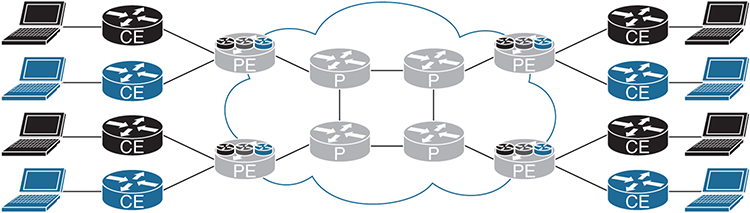
Figure 3-1 MPLS VPN Network Devices
The similarly shaded CE devices in Figure 3-1 represent a single overlay or customer network. These devices operate using only the global routing table. The PE devices use MPLS to separate traffic and maintain multiple VRF instances or multiple unique routing tables, one for each customer. Finally, the P devices perform label switching and IP routing to send messages to the appropriate destination PE router.
Note: For additional information, see RFC 4364, “BGP/MPLS IP Virtual Private Networks (VPNs).”
Multicast in an MPLS VPN Network
In order for the routers within a VRF instance to send and receive multicast messages, there must be some type of underlying transport mechanism. The transport mechanism must have the capability of supporting multiple VRF instances, potentially with overlapping IP unicast and multicast address space. In addition, the multicast implementation should have the ability to minimize the impact of the P routers by not overburdening them with too many multicast routes.
The network core must have the capability of transporting multicast messages for each VRF instance. This is accomplished in three ways:
![]() Using generic routing encapsulation (GRE)
Using generic routing encapsulation (GRE)
![]() Transporting multicast by using labels, which is called Multicast Label Distribution Protocol (MLDP), using headend replication, which sends the multicast message using unicast
Transporting multicast by using labels, which is called Multicast Label Distribution Protocol (MLDP), using headend replication, which sends the multicast message using unicast
![]() Using LDP
Using LDP
Note: You will find MLDP has two definitions. Multicast Label Distribution Protocol and Multipoint Label Distribution Protocol. Cisco documentation generally uses the term multicast and RFCs will generally use the term multipoint with a lowercase “m” (mLDP). They are the same.
Multicast Distribution Tree (MDT)
The first method developed for transporting multicast messages within an MPLS VPN network was GRE, which is widely used in current multicast deployments. Eric Rosen along with several others developed this strategy for transporting multicast messages over a unicast MPLS VPN infrastructure. Today, the Rosen method encompasses two fundamental techniques for multicast transport, the first using GRE and the second using MLDP. What differentiates the Rosen methodology is the concept of a default multicast distribution tree (MDT) and a data MDT. What defines the Rosen method is the use of an overlay to provide multicast over multicast. This method is also referred to as default MDT, default MDT-GRE, the Rosen model, the draft Rosen model, and Profile 0. (We like to keep things confusing as it adds to job security.)
Note: For additional information, see “Cisco Systems’ Solution for Multicast in MPLS/BGP IP VPNs” (https://tools.ietf.org/html/draft-rosen-vpn-mcast-15). Also see RFC 7441, “Encoding Multipoint LDP Forwarding Equivalence Classes (FECs) in the NLRI of BGP MCAST-VPN Routes.”
Default MDT
The default MDT includes all the PE routers that participate in a specific VPN. This is accomplished by using the same route distinguisher (RD) or through the use of importing and exporting routes with a route target (RT). If a group of routers within a VPN are exchanging unicast routing information, they are also in the same default MDT, and all receive the same unicast messages.
The default MDT is used as a mechanism for the PE routers within a VPN to exchange multicast messages with each other. For this to occur, the underlying infrastructure, which includes the IGP, MP-BGP, and Protocol Independent Multicast (PIM), must all be functioning correctly. CE equipment uses the default MDT to exchange multicast control messages. Messages are encapsulated over the core network using IP in IP with a GRE header, as shown in Figure 3-2, when using the default MDT.

Figure 3-2 Default MDT Header Information
Note: Example 3-12 shows the packet capture and provides additional detail.
Consider the default MDT as full-mesh or as a Multipoint-to-Multipoint (MP2MP) tree. When the default MDT has been configured, it is in an active state, or always operational, and is used to transmit PIM control messages (hello, join, and prune) between routers. Any time a multicast message is sent to the default MDT, all multicast routers participating in that VPN receive that message, as shown in Figure 3-3.

Figure 3-3 Default MDT MP2MP Tree
As you can imagine, this is not the most effective use of network bandwidth, and the challenge is addressed later in this chapter. For now, let’s take a look at how to configure a router to support the default MDT.
Example 3-1 is a configuration snippet from a router using IOS-XE. Notice that the RD 65000:1 is used for the VRF RED as well as the RT. The command mdt default 232.0.0.1 assigns a specific multicast address to the VRF. All routers participating in the default MDT must have the same multicast address assigned. (Do not forget to enable multicast routing for each VRF instance.)
The default PIM Source-Specific Multicast (PIM-SSM) range 232/8 is used for ease of configuration. If you plan to exchange multicast routing information with the Internet, however, best practice dictates using the 239/8 network.
Note: This chapter provides a substantial amount of configuration information. Please verify these parameters with the specific code you are using in your environment. These commands are provided for reference only.
Multicast routing and the MDT data in the VRF instance must be configured. Example 3-1 illustrates a configuration for IOS-XE.
Example 3-1 Default MDT Basic Configuration Using IOS-XE
ip multicast-routing vrf RED
!
vrf definition RED
 rd 65000:1
 !
 address-family ipv4
  mdt default 232.0.0.1
  route-target export 65000:1
  route-target import 65000:1
 exit-address-family
Example 3-2 show the IOS-XR commands.
Example 3-2 Default MDT Basic Configuration Using IOS-XR
router pim
 vrf RED
  address-family ipv4
   interface GigabitEthernet0/0/0/2
   !
  !
 !
!
multicast-routing
 address-family ipv4
  interface Loopback0
   enable
  !
  interface GigabitEthernet0/0/0/0
   enable
  !
  mdt source Loopback0
 !
 vrf RED
  address-family ipv4
   interface all enable
   mdt default ipv4 232.0.0.1
   mdt data 254
   mdt data 232.0.1.0/24
  !
 !
!
Note: The term VPN refers to a group of devices that exchange routing information and forward messages as part of a unique group. VRF instance refers to the routing instance that has be instantiated on a particular L3 device.
Data MDT
The Data MDT is the mechanism used to eliminate multicast data messages from being sent to every PE that participates in a specific VPN; instead, only those PE routers interested in the multicast forwarding tree for the specific group receive those multicast messages. Consider the data MDT as a Point-to-Multipoint (P2MP) tree with the source or root of the tree at the ingress PE device (that is, the PE router closest to the source of the multicast stream generated from the customer network).
The data MDT is not a unique or standalone multicast implementation mechanism but is a subset of the default MDT. As shown in Figure 3-4, the multicast sender is in the top-right corner, and the receiver is near the bottom-right side of the diagram. The data MDT establishes a separate tunnel from PE source to PE receiver(s) in the fashion that you would expect from a proper multicast implementation. In addition, replication of the multicast stream can also occur on a P device.
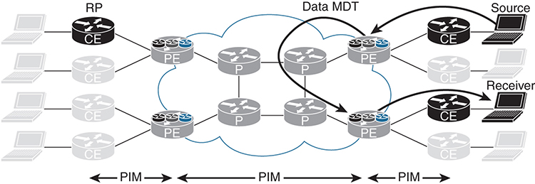
Figure 3-4 Data MDT
To configure a VRF instance for the data MDT, use following command set for IOS-XE:
mdt data group-address-range wildcard-bits [threshold kb/s] [list access-list]
group-address-range and wildcard-bits define the size of the pool. The first flow takes the first address from the pool, the second flow takes the second address from the pool, and so on, until the pool is depleted. Once the pool has been depleted, the router reuses addresses from the pool. In this event, you may have routers receiving messages that are not of interest and should be dropped. When selecting the pool size, attempt to minimize overlap for the most efficient transport of multicast messages. The threshold option is configurable from 1 to 4294967 and is used to determine when a multicast stream switches from the default MDT to the data MDT. Finally, the optional [list access-list] is used to define the (S, G) entries that are allowed to be used by the pool.
Note: When configuring IOS-XR, use mdt data [maximum number of MDTs] and mdt data [IPv4 multicast address range] to specify the number of multicast groups and the address range for the VPN.
Example 3-3 shows a configuration using IOS-XE. The address range 232.0.1.0 is used with the wildcard bits 0.0.0.255. In addition, the threshold is configured to switch to the data MDT when the multicast stream meets or exceeds 2 Kbps, as shown in Example 3-4.
Example 3-3 IOS-XE Configuration for Data MDT
vrf definition RED
 rd 65000:1
 !
 address-family ipv4
  mdt default 232.0.0.1
  mdt data 232.0.1.0 0.0.0.255 threshold 2
  mdt data threshold 2
  route-target export 65000:1
  route-target import 65000:1
 exit-address-family
Example 3-4 IOS-XR Configuration for Data MDT
multicast-routing
 vrf RED
  address-family ipv4
   interface all enable
   mdt default ipv4 232.0.0.1
   mdt data 254
   mdt data 232.0.1.0/24 threshold 2
  !
 !
!
Note: The data MDT is not required but highly recommended unless there are very few multicast streams and they are low-bandwidth.
Multicast Tunnel Interface (MTI)
The MTI is the tunnel interface that is automatically created for each multicast VPN. With the GRE MDT model, multicast traffic within each VPN is transported using a GRE tunnel. As shown in Example 3-5, when you use the show vrf RED command for IOS-XE, two GRE tunnels are created. In this case, one is for the default MDT and the other for the data MDT. (The Data MDT is within the defined threshold.)
Example 3-5 Multicast Tunnel Interface Using IOS-XE
R4# show vrf RED
  Name                             Default RD            Protocols   Interfaces
  RED                              65000:1               ipv4,ipv6   Et0/2
                                                                     Tu1
                                                                     Tu2
With IOS-XR, you can view the tunnel interface by using the show mfib vrf RED interface command. Example 3-6 shows the output from R4.
Example 3-6 show mfib Command Output
RP/0/0/CPU0:R4# show mfib vrf RED interface
Wed Feb 15 23:50:00.358 UTC

Interface : GigabitEthernet0/0/0/2 (Enabled)
SW Mcast pkts in : 23982, SW Mcast pkts out : 11376
TTL Threshold : 0
Ref Count : 6

Interface : mdtRED (Enabled)
SW Mcast pkts in : 0, SW Mcast pkts out : 0
TTL Threshold : 0
Ref Count : 11
For IOS-XR, the tunnel interface is mdtRED or mdt[VRF name].
Multicast Signaling in the Core
Both the default MDT and the data MDT require that the provider network transport multicast messages. Three options can be used to build PIM in the provider network:
![]() PIM Sparse-Mode (PIM-SM)
PIM Sparse-Mode (PIM-SM)
![]() Bidirectional PIM (Bidir-PIM)
Bidirectional PIM (Bidir-PIM)
![]() PIM Source-Specific Multicast (PIM-SSM) or just SSM
PIM Source-Specific Multicast (PIM-SSM) or just SSM
This book only covers the configuration of PIM-SSM, which is the recommended method. PIM-SM and Bidir-PIM are explained in detail in IP Multicast, Volume 1.
You may recall that the requirement for PIM-SSM is that all the clients must use Internet Group Management Protocol version 3 (IGMPv3) and that there are no requirements for a rendezvous point (RP). Fortunately, all Cisco devices that support MPLS also support IGMPv3. Implementing PIM-SSM is very simple when multicast routing is enabled, as shown in the following configurations.
On IOS-XE devices, use the following command: ip pim ssm default
Example 3-7 is a sample configuration using IOS-XR. SSM is enabled by default for the 232.0.0.0/8 range. You may choose to specify a range by using an access control list (ACL), as shown.
Example 3-7 SSM Configuration Example
 router pim
 address-family ipv4
  ssm range SSS-RANGE
 !

ipv4 access-list SSM-RANGE
 10 permit ipv4 232.0.0.0/8 any
What could be easier? No RP propagation mechanism, and you do not have even have to build in RP high availability! Remember that you must enable PIM-SSM on all P and PE devices in the network.
SSM is the only one of the three methods that does not have the ability to auto-discover the PIM neighbors in the default MDT using PIM. Therefore, you need to use another auto-discovery mechanism: the Border Gateway Protocol (BGP) address family MDT subsequent address family identifiers (MDT-SAFI). After the neighbors have been discovered, SSM can then be used to send PIM messages to those devices. This is configured under router bgp, using the MDT address family as shown in Example 3-8, which is for IOS-XE.
Example 3-8 BGP MDT Address Family
router bgp 65000
!
 address-family ipv4 mdt
  neighbor 192.168.0.1 activate
  neighbor 192.168.0.1 send-community both
  neighbor 192.168.0.2 activate
  neighbor 192.168.0.2 send-community both
 exit-address-family
Example 3-9 shows the same configuration using IOS-XR. Neighbor groups and session groups are used here for configuration simplicity, and only pertinent information is shown. Remember also that a route policy must be configured in order to send or receive BGP information.
Example 3-9 BGP MDT Configuration Using IOS-XR
route-policy ALLOW-ALL
  pass
end-policy
 !
router bgp 65000
 bgp router-id 192.168.0.4
 address-family ipv4 unicast
 !
 address-family vpnv4 unicast
 !
 address-family ipv4 mdt
 !
 session-group AS65000
  remote-as 65000
  update-source Loopback0
 !
 neighbor-group AS65000
  use session-group AS65000
  address-family ipv4 unicast
   route-policy ALLOW-ALL in
   route-policy ALLOW-ALL out
  !
  address-family vpnv4 unicast
   route-policy ALLOW-ALL in
   route-policy ALLOW-ALL out
  !
  address-family ipv4 mdt
   route-policy ALLOW-ALL in
   route-policy ALLOW-ALL out
  !
 neighbor 192.168.0.1
  use neighbor-group AS65000
 !
 neighbor 192.168.0.2
  use neighbor-group AS65000
Because route reflectors are used in this network, R4 (ingress PE connected to the receiver) only needs to establish an adjacency to those devices.
You verify the BGP adjacency within a specific VRF by using the show ip bgp ipv4 mdt vrf RED command, as shown for IOS-XE in Example 3-10.
Example 3-10 Verifying MDT BGP Adjacency Using IOS-XE
R4# show ip bgp ipv4 mdt vrf RED
BGP table version is 9, local router ID is 192.168.0.4
Status codes: s suppressed, d damped, h history, * valid, > best, i - internal,
              r RIB-failure, S Stale, m multipath, b backup-path, f RT-Filter,
              x best-external, a additional-path, c RIB-compressed,
Origin codes: i - IGP, e - EGP, ? - incomplete
RPKI validation codes: V valid, I invalid, N Not found

     Network          Next Hop            Metric LocPrf Weight Path
Route Distinguisher: 65000:1 (default for vrf RED)
 * i 192.168.0.3/32   192.168.0.3              0    100      0 ?
 *>i                  192.168.0.3              0    100      0 ?
 *>  192.168.0.4/32   0.0.0.0                                0 ?
 * i 192.168.0.5/32   192.168.0.5              0    100      0 ?
 *>i                  192.168.0.5              0    100      0 ?
 * i 192.168.0.6/32   192.168.0.6              0    100      0 ?
 *>i                  192.168.0.6              0    100      0 ?
For IOS-XR, you use the show bgp ipv4 mdt vrf RED command, as shown in Example 3-11.
Example 3-11 Verifying MDT BGP Adjacency Using IOS-XR
RP/0/0/CPU0:R4# show bgp ipv4 mdt vrf RED
Thu Feb 16 00:13:50.290 UTC
BGP router identifier 192.168.0.4, local AS number 65000
BGP generic scan interval 60 secs
Non-stop routing is enabled
BGP table state: Active
Table ID: 0xe0000000   RD version: 8
BGP main routing table version 8
BGP NSR Initial initsync version 2 (Reached)
BGP NSR/ISSU Sync-Group versions 0/0
BGP scan interval 60 secs

Status codes: s suppressed, d damped, h history, * valid, > best
              i - internal, r RIB-failure, S stale, N Nexthop-discard
Origin codes: i - IGP, e - EGP, ? - incomplete
   Network            Next Hop            Metric LocPrf Weight Path
Route Distinguisher: 65000:1
*>i192.168.0.3/96     192.168.0.3                   100      0 i
* i                   192.168.0.3                   100      0 i
*> 192.168.0.4/96     0.0.0.0                                0 i
*>i192.168.0.5/96     192.168.0.5                   100      0 i
* i                   192.168.0.5                   100      0 i
*>i192.168.0.6/96     192.168.0.6                   100      0 i
* i                   192.168.0.6                   100      0 i

Processed 4 prefixes, 7 paths
Because the previous command was executed on R4, notice the loopback addresses of the other routers within the RED VPN.
Default MDT in Action
Figure 3-5 provides a better understanding of the interaction between devices and the behavior of multicast in an MPLS environment.

Figure 3-5 Default MDT in Action
In order to replicate a typical network and eliminate the need to configure full-mesh MP-BGP, two route reflectors, R1 and R2, were added to the sample network. In this scenario, notice the behavior of multicast messages in the RED VRF. Host 20 (H20) is the multicast sender, H24 is the receiver, and R11 is the RP. The RED VRF is configured to use Auto-RP using sparse mode. This means that all the PE routers with the RED VRF running must use the ip pim vrf RED autorp listener command, and routers within the RED network must be configured with the ip pim autorp listener command. IOS-XR supports this functionality by default, and no additional configuration is required.
Data MDT Traffic Flow
The IP address of H20 (sender) is 172.16.12.20, the IP address of H24 (receiver) is 172.16.16.24, and the RP has an IP address in R11 of 172.16.3.11. H20 is sending a multicast stream to 224.1.1.20 at about 75 packets per second.
The sender (H20) begins to send traffic to the multicast group 224.1.1.20, but in this example, no receivers have registered to accept the stream. The gateway router (R12) forwards a special register message to the RP, registering the (*, G) and the gateway as a leaf in the tree. When H24 requests the multicast stream of 224.1.1.20, R16 sends a join message to the RP (R11). After a series of multicast messages, the tree switches to the source tree (S, G) (172.16.12.20, 224.1.1.20).
Note: Refer to Chapter 3, “IP Multicast at Layer 3,” in IP Multicast, Volume 1 for a detailed description of the shared-to-source tree process.
All the previous communication from the RED VPN occurs over the default MDT, which is sent to every PE device in the RED VPN.
Multicast traffic is now being sent from R4, the ingress router, to all PE devices in the RED VPN. The ingress device (R4) monitors the rate of the session. When the preconfigured threshold is crossed, the ingress router (R4) sends a PIM messages to all PE routers in the RED VPN, indicating the (S, G) (C-(S, G)) entry and the provider (S, G) (P-(S, G)) entry. The egress PE routers in the RED VPN that are interested in receiving the multicast stream send a join message to the ingress PE (R4). R4 then switches to the data MDT in three seconds unless it is configured for an immediate switchover.
Default MDT Example
To observe the behavior of the default MDT, this section shows how to reconfigure R4 to switch over to the data MDT at the highest configurable rate by using the mdt data threshold 4294967 command, as shown for IOS-XE in Example 3-12 and IOS-XR in Example 3-13.
Example 3-12 MDT Data Threshold Configuration Example Using IOS-XE
vrf definition RED
 rd 65000:1
 !
 address-family ipv4
  mdt default 232.0.0.1
  mdt data 232.0.1.0 0.0.0.255 threshold 4294967
  mdt data threshold 4294967
  route-target export 65000:1
  route-target import 65000:1
 exit-address-family
Example 3-13 MDT Data Threshold Configuration Example Using IOS-XR
route-policy PIM-Default
  set core-tree pim-default
end-policy

 vrf RED
  address-family ipv4
   rpf topology route-policy PIM-Default
   interface GigabitEthernet0/0/0/2

multicast-routing
 vrf RED
  address-family ipv4
   interface all enable
   mdt default ipv4 232.0.0.1
   mdt data 232.0.1.0/24 threshold 4294967
  !
 !
!
This keeps all multicast streams in the default MDT, unless of course a stream exceeds the threshold of 4,294,967 Kbps, which is not likely in this environment. You could also remove the mdt data commands altogether as an alternative solution.
As shown in Figure 3-3, all routers in the same VPN are connected using the same default MDT. You can observe this behavior by using the show ip pim vrf RED neighbor command for IOS-XE, as shown in Example 3-14.
Example 3-14 Showing the PIM Neighbor for VRF RED Using IOS-XE
R4# show ip pim vrf RED neighbor
PIM Neighbor Table
Mode: B - Bidir Capable, DR - Designated Router, N - Default DR Priority,
      P - Proxy Capable, S - State Refresh Capable, G - GenID Capable,
      L - DR Load-balancing Capable
Neighbor          Interface                Uptime/Expires    Ver   DR
Address                                                            Prio/Mode
172.16.4.12       Ethernet0/2              00:21:10/00:01:43 v2    1 / DR S P G
192.168.0.3       Tunnel1                  00:20:19/00:01:35 v2    1 / S P G
192.168.0.6       Tunnel1                  00:20:19/00:01:38 v2    1 / DR S P G
192.168.0.5       Tunnel1                  00:20:19/00:01:37 v2    1 / S P G
The equivalent command for IOS-XR is show pim vrf RED neighbor, as shown in Example 3-15.
Example 3-15 Showing the PIM Neighbor for VRF RED Using IOS-XE
RP/0/0/CPU0:R4# show pim vrf RED neighbor
Thu Feb 16 00:26:01.310 UTC


PIM neighbors in VRF RED
Flag: B - Bidir capable, P - Proxy capable, DR - Designated Router,
      E - ECMP Redirect capable
      * indicates the neighbor created for this router

Neighbor Address             Interface              Uptime    Expires  DR pri   Flags

172.16.4.4*                  GigabitEthernet0/0/0/2 3d23h     00:01:19 1  B E
172.16.4.12                  GigabitEthernet0/0/0/2 3d00h     00:01:22 1 (DR) P
192.168.0.3                  mdtRED                 3d23h     00:01:24 1
192.168.0.4*                 mdtRED                 3d23h     00:01:40 1
192.168.0.5                  mdtRED                 3d23h     00:01:32 1
192.168.0.6                  mdtRED                 3d23h     00:01:31 1 (DR)
From the output in Examples 3-14 and 3-15, notice that R3, R5, and R6 are PIM adjacent neighbors over Tunnel 1 for IOS-XE and mdtRED for IOS-XR, and there is also a PIM neighbor on the VRF RED interface, which is CE router R12.
You can look at a traffic capture between R5 and R9, as shown in Example 3-16, to get a tremendous amount of information about this exchange.
Example 3-16 Packet Capture on the Link Between R5 and R9
Ethernet Packet:  578 bytes
      Dest Addr: 0100.5E00.0001,   Source Addr: AABB.CC00.0920
      Protocol: 0x0800

IP    Version: 0x4,  HdrLen: 0x5,  TOS: 0x00
      Length: 564,   ID: 0xCA86,   Flags-Offset: 0x0000
      TTL: 252,   Protocol: 47,   Checksum: 0x4966 (OK)
      Source: 192.168.0.4,     Dest: 232.0.0.1

GRE   Present: 0x0 ( Chksum:0, Rsrvd:0, Key:0, SeqNum:0 )
      Reserved0: 0x000,  Version: 0x0,  Protocol: 0x0800

IP    Version: 0x4,  HdrLen: 0x5,  TOS: 0x00
      Length: 540,   ID: 0x0000,   Flags-Offset: 0x0000
      TTL: 58,   Protocol: 17 (UDP),   Checksum: 0xE593 (OK)
      Source: 172.16.12.20,     Dest: 224.1.1.20
UDP   Src Port: 37777,   Dest Port: 7050
      Length: 520,   Checksum: 0xB384 ERROR: F071

Data: *removed for brevity*
The first item to note is that R5 is not in the receiving path between H20 and H24. Why is R5 even seeing the multicast stream? The behavior of the default MDT is to send multicast messages to every PE in the VPN.
Starting at the top, notice that the L2 destination address is 0100.5E00.0001. This L2 multicast address maps to the default MDT multicast IP address 232.0.0.1. The IP header shows the source IP address 192.168.0.4, which is the loopback IP address of R4. In the next section is a GRE header, and below that is the original IP Multicast message. The encapsulated IP datagram shows the source address 172.16.12.20 (H20), destined to the multicast IP address 224.1.1.20. Finally, the UDP section shows the source port 37777 and the destination port 7050.
Very simply, the IP Multicast traffic from the RED VRF is encapsulated using the configured default MDT for VRF RED, hence the GRE tunnel.
MTI Example
You can determine what MTI the multicast stream is using by checking the state of the multicast routing table in the RED VRF for 224.1.1.20 by using the show ip mroute command for IOS-XE. Example 3-17 displays this output for VRF RED on R4.
Example 3-17 Verifying MTI Using IOS-XE
R4# show ip mroute vrf RED 224.1.1.20
IP Multicast Routing Table
Flags: D - Dense, S - Sparse, B - Bidir Group, s - SSM Group, C - Connected,
       L - Local, P - Pruned, R - RP-bit set, F - Register flag,
       T - SPT-bit set, J - Join SPT, M - MSDP created entry, E - Extranet,
       X - Proxy Join Timer Running, A - Candidate for MSDP Advertisement,
       U - URD, I - Received Source Specific Host Report,
       Z - Multicast Tunnel, z - MDT-data group sender,
       Y - Joined MDT-data group, y - Sending to MDT-data group,
       G - Received BGP C-Mroute, g - Sent BGP C-Mroute,
       N - Received BGP Shared-Tree Prune, n - BGP C-Mroute suppressed,
       Q - Received BGP S-A Route, q - Sent BGP S-A Route,
       V - RD & Vector, v - Vector, p - PIM Joins on route,
       x - VxLAN group
Outgoing interface flags: H - Hardware switched, A - Assert winner, p - PIM Join
 Timers: Uptime/Expires
 Interface state: Interface, Next-Hop or VCD, State/Mode
(*, 224.1.1.20), 01:05:53/stopped, RP 172.16.3.11, flags: SP
  Incoming interface: Tunnel1, RPF nbr 192.168.0.3
  Outgoing interface list: Null

(172.16.12.20, 224.1.1.20), 00:00:39/00:02:20, flags: T
  Incoming interface: Ethernet0/2, RPF nbr 172.16.4.12
  Outgoing interface list:
    Tunnel1, Forward/Sparse, 00:00:39/00:02:55
In the output in Example 3-17, notice that the multicast stream (S, G) in (172.16.12.20, 224.1.1.20) is incoming on Ethernet0/2 and outgoing on Tunnel 1.
You can look at the MTI of R4 by using the show interfaces tunnel 1 command and compare that with the previous packet capture. The tunnel source IP address matches with 192.168.0.4, the tunnel in multi-GRE/IP. Notice that the five-minute output rate also matches. Example 3-18 shows this output.
Example 3-18 Verifying MTI Details with show interfaces tunnel
R4# show interfaces tunnel 1
Tunnel1 is up, line protocol is up
  Hardware is Tunnel
  Interface is unnumbered. Using address of Loopback0 (192.168.0.4)
  MTU 17916 bytes, BW 100 Kbit/sec, DLY 50000 usec,
     reliability 255/255, txload 255/255, rxload 1/255
  Encapsulation TUNNEL, loopback not set
  Keepalive not set
  Tunnel linestate evaluation up
  Tunnel source 192.168.0.4 (Loopback0)
   Tunnel Subblocks:
      src-track:
         Tunnel1 source tracking subblock associated with Loopback0
          Set of tunnels with source Loopback0, 2 members (includes iterators), on interface <OK>
  Tunnel protocol/transport multi-GRE/IP
    Key disabled, sequencing disabled
    Checksumming of packets disabled
  Tunnel TTL 255, Fast tunneling enabled
  Tunnel transport MTU 1476 bytes
  Tunnel transmit bandwidth 8000 (kbps)
  Tunnel receive bandwidth 8000 (kbps)
  Last input 00:00:02, output 00:00:05, output hang never
  Last clearing of "show interface" counters 1d02h
  Input queue: 0/75/0/0 (size/max/drops/flushes); Total output drops: 0
  Queueing strategy: fifo
  Output queue: 0/0 (size/max)
  5 minute input rate 0 bits/sec, 0 packets/sec
  5 minute output rate 337000 bits/sec, 75 packets/sec
     39021 packets input, 3028900 bytes, 0 no buffer
     Received 0 broadcasts (3221 IP multicasts)
     0 runts, 0 giants, 0 throttles
     0 input errors, 0 CRC, 0 frame, 0 overrun, 0 ignored, 0 abort
     183556 packets output, 99558146 bytes, 0 underruns
     0 output errors, 0 collisions, 0 interface resets
     0 unknown protocol drops
     0 output buffer failures, 0 output buffers swapped out
You can use the show pim vrf RED mdt interface and show pim vrf RED mdt interface commands for IOS-XR as shown in Example 3-19.
Example 3-19 Verifying MTI Using IOS-XR
RP/0/0/CPU0:R4# show pim vrf RED mdt interface
Fri Feb 17 23:04:12.788 UTC

GroupAddress    Interface                    Source      Vrf

232.0.0.1       mdtRED                       Loopback0   RED


RP/0/0/CPU0:R4# show mrib vrf RED route 224.1.1.20
Fri Feb 17 23:01:10.460 UTC

IP Multicast Routing Information Base
Entry flags: L - Domain-Local Source, E - External Source to the Domain,
    C - Directly-Connected Check, S - Signal, IA - Inherit Accept,
    IF - Inherit From, D - Drop, ME - MDT Encap, EID - Encap ID,
    MD - MDT Decap, MT - MDT Threshold Crossed, MH - MDT interface handle
    CD - Conditional Decap, MPLS - MPLS Decap, EX - Extranet
    MoFE - MoFRR Enabled, MoFS - MoFRR State, MoFP - MoFRR Primary
    MoFB - MoFRR Backup, RPFID - RPF ID Set, X - VXLAN
Interface flags: F - Forward, A - Accept, IC - Internal Copy,
    NS - Negate Signal, DP - Don't Preserve, SP - Signal Present,
    II - Internal Interest, ID - Internal Disinterest, LI - Local Interest,
    LD - Local Disinterest, DI - Decapsulation Interface
    EI - Encapsulation Interface, MI - MDT Interface, LVIF - MPLS Encap,
    EX - Extranet, A2 - Secondary Accept, MT - MDT Threshold Crossed,
    MA - Data MDT Assigned, LMI - mLDP MDT Interface, TMI - P2MP-TE MDT Interface
    IRMI - IR MDT Interface
(172.16.12.20,224.1.1.20) RPF nbr: 172.16.4.12 Flags: RPF
  Up: 00:37:02
  Incoming Interface List
    GigabitEthernet0/0/0/2 Flags: A, Up: 00:37:02
  Outgoing Interface List
    mdtRED Flags: F NS MI, Up: 00:37:02
The F flag indicates that multicast traffic is being forwarded, the NS flag is used with PIM-SM to indicate a shortest-path tree (SPT) switchover, and the MI flag indicates that it is an MDT interface.
Data MDT Example
This section examines the behavior of the data MDT, using the same example shown in Figure 3-4. R11 is the RP, H20 is the sender, and H24 is the receiver for multicast group 224.1.1.20. In this scenario, H20 is sending traffic to group 224.1.1.20. Just as in any PIM-SM configuration, R12 registers with the RP (R12). Because there are currently no receivers interested in the traffic, R12 does not forward any multicast messages. When H24 joins the 224.1.1.20 group, it sends the join message to the RP (R12). With an interested receiver, R12 begins to forward the traffic to R4 (PE).
R4 sends multicast messages to the default MDT. This means that every router participating in the RED multicast VPN receives the message, including R3, R5, and R6. Both R3 and R5 drop the traffic because they do not have any receivers interested in the multicast stream. R6, on the other hand, has an interested receiver downstream, which is H24. R6 sends a join message to R4, as shown by the packet capture between R6 and R10. Also note that this is not a GRE encapsulated packet but is sent natively, as shown in Example 3-20.
Example 3-20 Native Default MDT
Ethernet Packet:  68 bytes
      Dest Addr: 0100.5E00.000D,   Source Addr: AABB.CC00.0600
      Protocol: 0x0800

IP    Version: 0x4,  HdrLen: 0x5,  TOS: 0xC0 (Prec=Internet Contrl)
      Length: 54,   ID: 0x9913,   Flags-Offset: 0x0000
      TTL: 1,   Protocol: 103 (PIM),   Checksum: 0x14D2 (OK)
      Source: 192.168.106.6,     Dest: 224.0.0.13

PIM   Ver:2 , Type:Join/Prune , Reserved: 0 , Checksum : 0x008B (OK)
      Addr Family: IP , Enc Type: 0 , Uni Address: 192.168.106.10
      Reserved: 0 , Num Groups: 1 , HoldTime: 210
      Addr Family: IP , Enc Type: 0 , Reserved: 0 , Mask Len: 32
      Group Address:232.0.1.0
      Num Joined Sources: 1 ,   Num Pruned Sources: 0
      Joined/Pruned Srcs:       Addr Family: IP , Enc Type: 0 , Reserved: 0
      S: 1 , W: 0, R:0,  Mask Len: 32
      Source Address:192.168.0.4
R4 continues to send multicast messages to the default MDT (232.0.0.1) until the threshold is reached, at which time it moves the stream from the default MDT to the data MDT, which in this example is the multicast address 232.0.1.0.
It is important to understand that there are two multicast operations happening simultaneously:
![]() The CE overlay
The CE overlay
![]() The P/PE underlay
The P/PE underlay
Example 3-21 provides some practical configuration, debugging information, and packet captures that assist in explaining the process in greater detail. In order to switch to the data MDT, you need to reconfigure R4 to switch over to the data MDT at a lower rate. As shown in Example 3-21, which uses IOS-XE, you can use 2 Kbps and configure R4 with the mdt data threshold 2 command.
Example 3-21 Configuring the Data MDT Threshold Using IOS-XE
vrf definition RED
 rd 65000:1
 !
 address-family ipv4
  mdt default 232.0.0.1
  mdt data 232.0.1.0 0.0.0.255 threshold 2
  mdt data threshold 2
Example 3-22 shows the same configuration using IOS-XR.
Example 3-22 Configuring the Data MDT Threshold Using IOS-XR
multicast-routing
!
 vrf RED
  address-family ipv4
   interface all enable
   mdt default ipv4 232.0.0.1
   mdt data 232.0.1.0/24 threshold 2
The expectation now is that the multicast stream sent from H20 will use the following path: R12, R4, R8, R10, R6, R16, H24. The switchover process takes three seconds.
You can verify the existence of the default MDT with the show ip pim vrf RED mdt command on R4, as shown in Example 3-23, which uses IOS-XE. In this example, the * implies the default MDT.
Example 3-23 PIM Default MDT with IOS-XE
R4# show ip pim vrf RED mdt
  * implies mdt is the default MDT, # is (*,*) Wildcard,
  > is non-(*,*) Wildcard
  MDT Group/Num   Interface   Source                   VRF
* 232.0.0.1       Tunnel1     Loopback0                RED
Example 3-24 shows the cache entries for the default MDT for IOS-XE, using the show pim vrf RED mdt cache command.
Example 3-24 PIM Default MDT Cache
RP/0/0/CPU0:R4# show pim vrf RED mdt cache
Fri Feb 17 21:41:52.136 UTC


Core Source      Cust (Source, Group)                Core Data        Expires
192.168.0.4      (172.16.12.20, 224.1.1.20)          232.0.1.0        00:02:20
With IOS-XR, you use the show mrib vrf RED mdt-interface detail command, as shown in Example 3-25.
Example 3-25 MRIB VRF RED
RP/0/0/CPU0:R4# show mrib vrf RED mdt-interface detail
Fri Feb 17 23:06:39.648 UTC
IP Multicast MRIB MDT ifhandle Interface DB
MH - Handle update count, I - Intranet route count, EX - Extranet route count, Up - Uptime
0x90(mdtRED)  TID:0xe0000012  MH:1  I:3  EX:0  Up:01:28:17
    MDT route forward-reference DB:
    (172.16.3.11,224.0.1.39/32) [tid:0xe0000012] recollapse: FALSE
    (172.16.3.11,224.0.1.40/32) [tid:0xe0000012] recollapse: FALSE
    (172.16.12.20,224.1.1.20/32) [tid:0xe0000012] recollapse: FALSE
To validate that the data MDT is in use, use the show ip pim vrf RED mdt send command on R4, as shown in Example 3-26 for IOS-XR. The (S, G) of (172.16.12.20, 224.1.1.20) is now part of the data MDT.
Example 3-26 PIM VRF Data MDT Send
R4# show ip pim vrf RED mdt send

MDT-data send list for VRF: RED
  (source, group)                     MDT-data group/num   ref_count
  (172.16.12.20, 224.1.1.20)          232.0.1.0            1
The data MDT is 232.0.1.0, as shown in Example 3-26.
Using a similar command with IOS-XR, show pim vrf RED mdt cache, Example 3-27 shows that the data MDT is 232.0.1.6.
Example 3-27 PIM VRF Data MDT IP Address
RP/0/0/CPU0:R4# show pim vrf RED mdt cache
Fri Feb 17 23:10:08.583 UTC

Core Source      Cust (Source, Group)                Core Data        Expires
192.168.0.4      (172.16.12.20, 224.1.1.20)          232.0.1.6        00:02:56
Now that the SPT has been established, there is optimal multicast traffic flow from source to receiver. Looking at a packet capture between R6 and R10 with the IOS-XE example, you verify that the data MDT is in operation, as shown in Example 3-28.
Example 3-28 Data MDT in Operation
Ethernet Packet:  578 bytes
      Dest Addr: 0100.5E00.0100,   Source Addr: AABB.CC00.0A20
      Protocol: 0x0800

IP    Version: 0x4,  HdrLen: 0x5,  TOS: 0x00
      Length: 564,   ID: 0x4447,   Flags-Offset: 0x0000
      TTL: 253,   Protocol: 47,   Checksum: 0xCDA6 (OK)
      Source: 192.168.0.4,     Dest: 232.0.1.0

GRE   Present: 0x0 ( Chksum:0, Rsrvd:0, Key:0, SeqNum:0 )
      Reserved0: 0x000,  Version: 0x0,  Protocol: 0x0800

IP    Version: 0x4,  HdrLen: 0x5,  TOS: 0x00
      Length: 540,   ID: 0x0000,   Flags-Offset: 0x0000
      TTL: 58,   Protocol: 17 (UDP),   Checksum: 0xE593 (OK)
      Source: 172.16.12.20,     Dest: 224.1.1.20

UDP   Src Port: 37777,   Dest Port: 7050
      Length: 520,   Checksum: 0xB384 ERROR: EF72

Data: *removed for brevity*
From the packet capture, you can see that the destination IP address is 232.0.1.0, which is the first multicast IP address defined in the pool. Also notice the GRE information and the encapsulated IP Multicast header that is part of VRF RED. Remember that the data MDT is now using SPT for optimal routing.
You can use yet another IOS-XE command to view the functionality of the default MDT and the data MDT with the command show ip mfib vrf RED 224.1.1.20, as shown in Example 3-29.
Example 3-29 Data MDT Packet Count Using IOS-XE
R4# show ip mfib vrf RED 224.1.1.20
Entry Flags:    C - Directly Connected, S - Signal, IA - Inherit A flag,
                ET - Data Rate Exceeds Threshold, K - Keepalive
                DDE - Data Driven Event, HW - Hardware Installed
                ME - MoFRR ECMP entry, MNE - MoFRR Non-ECMP entry, MP - MFIB
                MoFRR Primary, RP - MRIB MoFRR Primary, P - MoFRR Primary
                MS  - MoFRR  Entry in Sync, MC - MoFRR entry in MoFRR Client.
I/O Item Flags: IC - Internal Copy, NP - Not platform switched,
                NS - Negate Signalling, SP - Signal Present,
                A - Accept, F - Forward, RA - MRIB Accept, RF - MRIB Forward,
                MA - MFIB Accept, A2 - Accept backup,
                RA2 - MRIB Accept backup, MA2 - MFIB Accept backup

Forwarding Counts: Pkt Count/Pkts per second/Avg Pkt Size/Kbits per second
Other counts:      Total/RPF failed/Other drops
I/O Item Counts:   FS Pkt Count/PS Pkt Count
VRF RED
 (*,224.1.1.20) Flags: C
   SW Forwarding: 0/0/0/0, Other: 0/0/0
   Tunnel1, MDT/232.0.0.1 Flags: A
 (172.16.12.20,224.1.1.20) Flags: ET
   SW Forwarding: 5547/77/540/328, Other: 0/0/0
   Ethernet0/2 Flags: A
   Tunnel1, MDT/232.0.1.0 Flags: F NS
     Pkts: 4784/0
With IOS-XR the equivalent command is show mfib vrf RED route 224.1.1.20, as shown in Example 3-30.
Example 3-30 Data MDT Packet Count Using IOS-XR
RP/0/0/CPU0:R4# show mfib vrf RED route 224.1.1.20
Thu Feb 16 00:47:58.929 UTC

IP Multicast Forwarding Information Base
Entry flags: C - Directly-Connected Check, S - Signal, D - Drop,
  IA - Inherit Accept, IF - Inherit From, EID - Encap ID,
  ME - MDT Encap, MD - MDT Decap, MT - MDT Threshold Crossed,
  MH - MDT interface handle, CD - Conditional Decap,
  DT - MDT Decap True, EX - Extranet, RPFID - RPF ID Set,
  MoFE - MoFRR Enabled, MoFS - MoFRR State, X - VXLAN
Interface flags: F - Forward, A - Accept, IC - Internal Copy,
  NS - Negate Signal, DP - Don't Preserve, SP - Signal Present,
  EG - Egress, EI - Encapsulation Interface, MI - MDT Interface,
  EX - Extranet, A2 - Secondary Accept
Forwarding/Replication Counts: Packets in/Packets out/Bytes out
Failure Counts: RPF / TTL / Empty Olist / Encap RL / Other

(172.16.12.20,224.1.1.20),  Flags:
  Up: 01:09:21
  Last Used: 00:00:00
  SW Forwarding Counts: 165863/165863/89566020
  SW Replication Counts: 165863/0/0
  SW Failure Counts: 0/0/0/0/0
  mdtRED Flags:  F NS MI, Up:00:34:52
  GigabitEthernet0/0/0/2 Flags:  A, Up:00:34:52
The commands in the preceding examples provide a wealth of information for troubleshooting, such as the packet count and the specific tunnel interface.
Multicast LDP (MLDP)
MLDP is an extension to LDP used to facilitate the transportation of multicast messages in an MPLS network. MLDP supports P2MP and MP2MP label-switched paths (LSPs). With MLDP, you can use the same encapsulation method as with the unicast messages, which reduces the complexity of the network. MLDP is a true pull-model implementation in that the PE closest to the receiver is the device to initiate the LSP.
Figure 3-6 illustrates the MLDP topology. Receivers send traffic upstream, toward the root, and the source sends traffic downstream.
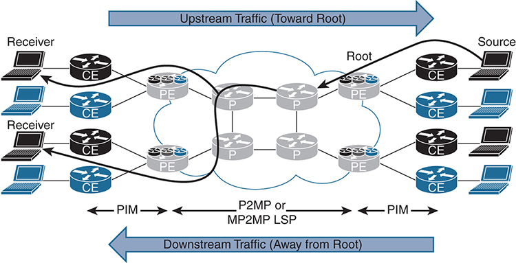
Figure 3-6 MLDP Topology
Every time there is a new receiver, a multipoint LSP (MP-LSP) is either created or joined. Every MP-LSP must have a root (in the MPLS core). MLDP uses downstream on-demand label allocation, with labels allocated by the downstream PE (closest to the receiver) toward the upstream PE (closest to the root). The ingress router is the PE closest to the multicast source, and the flow away from the root toward the receiver is called the downstream traffic. The egress router in this case is the PE closest to the receiver. Both the ingress and egress devices (PEs) participate in the native IP Multicast domain (PIM) on the customer side and also the MPLS domain (MLDP) on the provider side.
How did LDP get the capability to support multicast signaling and Reverse Path Forwarding (RPF)? LDP does not have any mechanism to support multicast capabilities or signaling. The draft standard has been proposed (see https://tools.ietf.org/html/draft-ietf-mpls-ldp-capabilities-02), and it provides guidelines for advertising the type-length-value (TLV) capability at the beginning of the session after LDP is established. Three capability TLVs are defined in the implementation of MLDP:
![]() P2MP: TLV 0x0508
P2MP: TLV 0x0508
![]() MP2MP: TLV 0x0509
MP2MP: TLV 0x0509
![]() Make Before Break (MBB): TLV 0x050A
Make Before Break (MBB): TLV 0x050A
Cisco does not currently support MBB.
FEC Elements
The Forwarding Equivalence Class (FEC) describes a set of packets with a similar characteristic for forwarding and that are bound to the same outbound MPLS label. With MLDP, the multicast information is transmitted for the control plane to function correctly. MLDP uses the label mapping message to create the MP-LSP hop-by-hop to the root ingress PE device. This path is established using IGP to find the most efficient path to the root, using the appropriate routing metrics. The label mapping message carries additional information known as TLVs. The FEC TLV contains FEC elements, which actually define the set of packets that will use the LSP. This FEC TLV for multicast contains the following information:
![]() Tree type: Point-to-point or bidirectional tree
Tree type: Point-to-point or bidirectional tree
![]() Address family: The type of stream (IPv4 or IPv6) the tree is replicating, which defines the root address type.
Address family: The type of stream (IPv4 or IPv6) the tree is replicating, which defines the root address type.
![]() Address length: The length of the root address.
Address length: The length of the root address.
![]() Root node address: The actual root address of the MP-LSP within the MPLS core (IPv4 or IPv6).
Root node address: The actual root address of the MP-LSP within the MPLS core (IPv4 or IPv6).
![]() Opaque value: The stream information that uniquely identifies this tree to the root. The opaque value contains additional information that defines the (S, G), PIM-SSM Transit, or it can be an LSP identifier to define the default/data MDTs in a multicast VPN (MVPN) application. Currently, four multicast mechanisms are supported, each with a unique opaque value:
Opaque value: The stream information that uniquely identifies this tree to the root. The opaque value contains additional information that defines the (S, G), PIM-SSM Transit, or it can be an LSP identifier to define the default/data MDTs in a multicast VPN (MVPN) application. Currently, four multicast mechanisms are supported, each with a unique opaque value:
![]() IPv4 PIM-SSM transit: This allows global PIM-SSM streams to be transported across the MPLS core. The opaque value contains the actual (S, G), which reside in the global mroute table of the ingress and egress PE routers.
IPv4 PIM-SSM transit: This allows global PIM-SSM streams to be transported across the MPLS core. The opaque value contains the actual (S, G), which reside in the global mroute table of the ingress and egress PE routers.
![]() IPv6 PIM-SSM transit: This is similar to IPv4 PIM-SSM but for IPv6 streams in the global table.
IPv6 PIM-SSM transit: This is similar to IPv4 PIM-SSM but for IPv6 streams in the global table.
![]() Multicast VPN: This allows VPNv4 traffic to be transported across the default MDT or the data MDT using label switching. The current method is to use mGRE tunneling (which is reviewed earlier in this chapter). Use MLDP to replace the mGRE tunnel with an MP-LSP tunnel. Multicast VPN is independent of the underlying tunnel mechanism.
Multicast VPN: This allows VPNv4 traffic to be transported across the default MDT or the data MDT using label switching. The current method is to use mGRE tunneling (which is reviewed earlier in this chapter). Use MLDP to replace the mGRE tunnel with an MP-LSP tunnel. Multicast VPN is independent of the underlying tunnel mechanism.
![]() Direct MDT or VPNv4 transit: This opaque value allows VPNv4 streams to be directly built without the need for the default MDT to exist. This is useful for high-bandwidth streams with selective PEs requiring the multicast stream. Currently, this is not a supported feature.
Direct MDT or VPNv4 transit: This opaque value allows VPNv4 streams to be directly built without the need for the default MDT to exist. This is useful for high-bandwidth streams with selective PEs requiring the multicast stream. Currently, this is not a supported feature.
In-Band Signaling Operation
In-band signaling uses opaque LSAs directly between the ingress PE and the egress PE with MLDP. Figure 3-7 shows the operation, which is as follows:
Step 1. PE3 (egress PE) receives an IGMP join from a receiver. In this example, the receiver is directly connected to the PE. In a real-life scenario, the CE sends a PIM (*, G) join toward the PE. PE3 creates a label-mapping message with FEC TLV with the opaque value. The root address in the FEC element is derived from the BGP next hop or source.
Note: All PEs connected to the receiver create the same FEC element.
Step 2. Once the source begins transmitting, PE3 builds an MP-LSP toward PE1 (considered the root of the tree). At each hop along the way, the P routers use the same FEC element and associate a local label map, which will be label swapped. Finally, when the packet is received, the ingress PE parses the opaque value to extract the multicast stream information.
Step 3. When the ingress PE receives the multicast stream, it forwards it on to the correct interface to which the receiver is connected.

Out-of-Band (Overlay) Signaling Operation
The other signaling method used to build MLDP is out-of-band signaling.
Figure 3-8 illustrates this procedure, which is as follows:
Step 1. PE3 (egress PE) receives an IGMP join from a receiver.
Step 2. PE3 (egress PE) creates an FEC and then builds the multicast LSP hop-by-hop to the root, based on the FEC information using overlay signaling.
Step 3. PE3 (egress PE) builds the multicast LSP hop-by-hop to the root, based on the FEC information, using the overlay signaling mechanism. (The overlay creates a unique FEC value that is used to forward the multicast stream from PE1 to PE3.)
Step 4. Multicast messages are transmitted from PE1 to PE3, using the labels created from the out-of-band signaling.
The common overlay signaling model used to build the out-of-band (overlay) signaling includes PIM and the BGP address family.

Figure 3-8 Out-of-Band Signaling Operation
Default MDT MLDP
The default MDT-GRE, examined earlier in this chapter, uses IP-in-IP with a GRE header to establish connectivity between all PE devices within a VPN. This section builds on the concept of the default MDT and the data MDT, but in this situation, MLDP is used as the transport mechanism.
The default MDT uses an MP2MP bidirectional tree to send multicast hello, join, and prune messages to all the PE routers participating in a particular MVPN. Much as when using the default MDT with GRE, all devices must be aware and able to send and receive multicast messages to all the peers in the VPN. With MLDP, you can take advantage of the underlying LSPs to transport multicast messages, which eliminates the need to run PIM in the core of the network. PIM configured on the customer side of the PE device is still required to establish connectivity with those devices.
The default MDT MLDP is one of the most popular options when implementing MLDP as it offers an easy transition to MLDP compared to some of the other methods. MDT MLDP is also sometimes referred to as Multidirectional Inclusive Provider Multicast Service Interface (MI-PMSI) or Profile 1. (Profiles are explained later in this chapter.)
The first step is to enable PIM MPLS on all P and PE devices in the network by using the ip pim mpls source Loopback0 command. The P devices must also understand the multicast labels as they may have to preform multicast packet replication. The second step is to create a VPN ID by using the vpn id command. The VPN ID must be consistent across all PE device in the same VPN. This command is the equivalent of the MDT group address used on the default MDT GRE.
Note: In this example, the same VPN ID as the RD is used, but this is not a requirement.
Finally, you need to configure at least one device as the root of the MP2MP tree by using the mdt default mpls mldp [IP_Address] IOS-XE command or the mdt default mldp ipv4 [IP_Address] IOS-XR command. The root of the MDT tree must be configured on all PE devices within a VPN. This is statically configured as there is not an automatic discovery method today. When selecting the root, be sure to choose a device that has the capability to accommodate the additional load. This means you should avoid using a route reflector as the root as may adversely affect the control plane and consequently take down your entire network.
Default MDT MLDP Root High Availability
If only one root is configured, what happens when that device fails? No multicast messages flow across the network. There are two options to address this. The first is to use anycast root node redundancy (RNR). This is accomplished by configuring a primary root and a backup root, which involves creating an additional loopback on the primary root and the backup root that advertise the same IP address. The difference is that the IP address of the primary root advertises the route with a longer mask. For example, referring to Figure 3-5, you could add a loopback address to R8 as 192.168.0.254 with subnet mask 255.255.255.255 (/32) and also add a loopback address to R9 with the same address 192.168.0.254, but with the shorter subnet mask 255.255.255.254 (/31).
Remember that routes are chosen by longest match first. This makes R8 the root, and in the event of a failure, R9 takes over. The issue with this implementation is that when R8 fails, you have to wait for IGP to reconverge to make R9 the new root.
An alternative solution is to configure two devices as the root. Figure 3-9 shows an example in which R8 and R9 are chosen as the root. The upside to this implementation is that immediate failover occurs in the event that the root is unavailable, but the downside is that it creates additional MLDP state in the core of the network. As the network architect, you need to determine if the additional overhead is worth the reduced failover time.
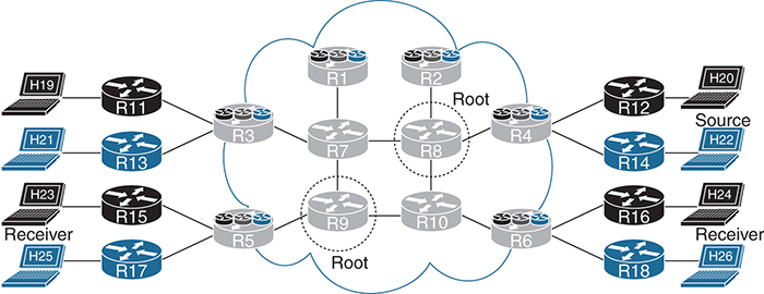
Figure 3-9 MLDP Root High Availability
MLDP in Action
This section shows how to configure VRF BLU for MLDP, with R8 and R9 as the root of the tree. In this example, VRF BLU is configured for auto-RP, using R13 as the RP. H22 (172.17.14.22) is configured to send traffic to multicast address 224.2.2.22. H25 and H26 are set up as receivers, as shown in Figure 3-9.
Default MDT MLDP Example
As shown in Examples 3-31 and 3-32, PIM MPLS is configured for Loopback0, the VPN ID is 65000:2, and two roots are configured for high availability: R8 (192.168.0.8) and R9 (192.168.0.9).
Note: All core devices must also be configured to support MPLS MLDP.
Example 3-31 Default MDT MLDP Configuration Using IOS-XE
PE routers#
vrf definition BLU
 rd 65000:2
 vpn id 65000:2
 !
 address-family ipv4
  mdt default mpls mldp 192.168.0.8
  mdt default mpls mldp 192.168.0.9
  route-target export 65000:2
  route-target import 65000:2
 exit-address-family
Example 3-32 Default MDT MLDP Configuration Using IOS-XR
PE routers#
mpls ldp
 mldp
 !
vrf BLU
 vpn id 65000:2
 address-family ipv4 unicast
   import route-target
    65000:2
   export route-target
    65000:2
 !
route-policy Data-MDT-mLDP
  set core-tree mldp
end-policy
!
multicast-routing
 vrf BLU
  address-family ipv4
   interface all enable
   mdt default mldp ipv4 192.168.0.8
   mdt default mldp ipv4 192.168.0.9
   !
router pim
 vrf BLU
  address-family ipv4
   rpf topology route-policy Data-MDT-mLDP
   interface GigabitEthernet0/0/0/1
You need to verify MLDP neighbor relationships by using the show mpls mldp neighbors command, as shown in Examples 3-33 and 3-34, from R7. This is one of the few commands that are consistent across IOS-XE and IOS-XR.
Example 3-33 MPLS MLDP Neighbors Using IOS-XE
R7# show mpls mldp neighbors

 MLDP peer ID    : 192.168.0.1:0, uptime 1w2d Up,
  Target Adj     : No
  Session hndl   : 1
  Upstream count : 0
  Branch count   : 0
  Path count     : 1
  Path(s)        : 192.168.71.1      LDP Ethernet0/3
  Nhop count     : 0

 MLDP peer ID    : 192.168.0.8:0, uptime 1w2d Up,
  Target Adj     : No
  Session hndl   : 3
  Upstream count : 1
  Branch count   : 0
  Path count     : 1
  Path(s)        : 192.168.87.8      LDP Ethernet0/1
  Nhop count     : 1
  Nhop list      : 192.168.87.8

 MLDP peer ID    : 192.168.0.9:0, uptime 1w2d Up,
  Target Adj     : No
  Session hndl   : 4
  Upstream count : 1
  Branch count   : 0
  Path count     : 1
  Path(s)        : 192.168.97.9      LDP Ethernet0/0
  Nhop count     : 1
  Nhop list      : 192.168.97.9

 MLDP peer ID    : 192.168.0.3:0, uptime 5d21h Up,
  Target Adj     : No
  Session hndl   : 6
  Upstream count : 0
  Branch count   : 2
  Path count     : 1
  Path(s)        : 192.168.73.3      LDP Ethernet0/2
  Nhop count     : 0
Example 3-34 MPLS MLDP Neighbors Using IOS-XR
RP/0/0/CPU0:R7# show mpls mldp neighbors
Sat Feb 18 22:26:00.867 UTC
mLDP neighbor database
 MLDP peer ID      : 192.168.0.1:0, uptime 00:31:53 Up,
  Capabilities     : Typed Wildcard FEC, P2MP, MP2MP
  Target Adj       : No
  Upstream count   : 0
  Branch count     : 0
  Label map timer  : never
  Policy filter in :
  Path count       : 1
  Path(s)          : 192.168.71.1      GigabitEthernet0/0/0/3 LDP
  Adj list         : 192.168.71.1      GigabitEthernet0/0/0/3
  Peer addr list   : 192.168.71.1
                   : 192.168.0.1

 MLDP peer ID      : 192.168.0.3:0, uptime 00:31:53 Up,
  Capabilities     : Typed Wildcard FEC, P2MP, MP2MP
  Target Adj       : No
  Upstream count   : 0
  Branch count     : 2
  Label map timer  : never
  Policy filter in :
  Path count       : 1
  Path(s)          : 192.168.73.3      GigabitEthernet0/0/0/2 LDP
  Adj list         : 192.168.73.3      GigabitEthernet0/0/0/2
  Peer addr list   : 192.168.73.3
                   : 192.168.0.3

 MLDP peer ID      : 192.168.0.8:0, uptime 00:31:53 Up,
  Capabilities     : Typed Wildcard FEC, P2MP, MP2MP
  Target Adj       : No
  Upstream count   : 1
  Branch count     : 1
  Label map timer  : never
  Policy filter in :
  Path count       : 1
  Path(s)          : 192.168.87.8      GigabitEthernet0/0/0/1 LDP
  Adj list         : 192.168.87.8      GigabitEthernet0/0/0/1
  Peer addr listw  : 192.168.108.8
                   : 192.168.87.8
                   : 192.168.84.8
                   : 192.168.82.8
                   : 192.168.0.8

 MLDP peer ID      : 192.168.0.9:0, uptime 00:31:53 Up,
  Capabilities     : Typed Wildcard FEC, P2MP, MP2MP
  Target Adj       : No
  Upstream count   : 1
  Branch count     : 1
  Label map timer  : never
  Policy filter in :
  Path count       : 1
  Path(s)          : 192.168.97.9      GigabitEthernet0/0/0/0 LDP
  Adj list         : 192.168.97.9      GigabitEthernet0/0/0/0
  Peer addr list   : 192.168.97.9
                   : 192.168.109.9
                   : 192.168.95.9
                   : 192.168.0.9
The output in Examples 3-33 and 3-34 shows that R7 has established an MLDP neighbor relationships. You can run the show mpls mldp neighbors command from any P or PE device to determine the appropriate neighbors.
You also need to verify that the root of the default MDT trees are established by using the show mpls mldp root command for both IOS-XE and IOS-XR, as shown in Examples 3-35 and 3-36.
Example 3-35 MPLS MLDP Root Using IOS-XE
R7# show mpls mldp root
 Root node    : 192.168.0.8
  Metric      : 11
  Distance    : 110
  Interface   : Ethernet0/1 (via unicast RT)
  FEC count   : 1
  Path count  : 1
  Path(s)     : 192.168.87.8     LDP nbr: 192.168.0.8:0     Ethernet0/1

 Root node    : 192.168.0.9
  Metric      : 11
  Distance    : 110
  Interface   : Ethernet0/0 (via unicast RT)
  FEC count   : 1
  Path count  : 1
  Path(s)     : 192.168.97.9     LDP nbr: 192.168.0.9:0     Ethernet0/0
Example 3-36 MPLS MLDP Root Using IOS-XR
RP/0/0/CPU0:R7# show mpls mldp root
Sat Feb 18 22:27:11.592 UTC
mLDP root database
 Root node    : 192.168.0.8
  Metric      : 11
  Distance    : 110
  FEC count   : 1
  Path count  : 1
  Path(s)     : 192.168.87.8     LDP nbr: 192.168.0.8:0

 Root node    : 192.168.0.9
  Metric      : 11
  Distance    : 110
  FEC count   : 1
  Path count  : 1
  Path(s)     : 192.168.97.9     LDP nbr: 192.168.0.9:0
One item that is interesting to note is that the P devices are all aware of where the roots are in the tree. The output in Example 3-36 is from R7, one of the P devices.
With the command show mpls mldp bindings, you can view the labels associated with the MP2MP trees, as shown in Examples 3-37 and 3-38.
Example 3-37 MPLS MLDP Bindings Using IOS-XE
R7# show mpls mldp bindings
System ID: 7
Type: MP2MP, Root Node: 192.168.0.8, Opaque Len: 14
Opaque value: [mdt 65000:2 0]
lsr: 192.168.0.8:0, remote binding[U]: 32, local binding[D]: 32 active
lsr: 192.168.0.3:0, local binding[U]: 31, remote binding[D]: 38

System ID: 8
Type: MP2MP, Root Node: 192.168.0.9, Opaque Len: 14
Opaque value: [mdt 65000:2 0]
lsr: 192.168.0.9:0, remote binding[U]: 35, local binding[D]: 34 active
lsr: 192.168.0.3:0, local binding[U]: 33, remote binding[D]: 39
Example 3-38 MPLS MLDP Bindings Using IOS-XR
RP/0/0/CPU0:R7# show mpls mldp bindings
Sat Feb 18 22:42:44.968 UTC
mLDP MPLS Bindings database

LSP-ID: 0x00001 Paths: 3 Flags:
 0x00001 MP2MP  192.168.0.9 [mdt 65000:2 0]
   Local Label: 24017 Remote: 24018 NH: 192.168.97.9 Inft: GigabitEthernet0/0/0/0 Active
   Local Label: 24015 Remote: 24023 NH: 192.168.73.3 Inft: GigabitEthernet0/0/0/2
   Local Label: 24019 Remote: 24018 NH: 192.168.87.8 Inft: GigabitEthernet0/0/0/1

LSP-ID: 0x00002 Paths: 3 Flags:
 0x00002 MP2MP  192.168.0.8 [mdt 65000:2 0]
   Local Label: 24018 Remote: 24017 NH: 192.168.87.8 Inft: GigabitEthernet0/0/0/1 Active
   Local Label: 24016 Remote: 24022 NH: 192.168.73.3 Inft: GigabitEthernet0/0/0/2
   Local Label: 24020 Remote: 24019 NH: 192.168.97.9 Inft: GigabitEthernet0/0/0/0
Traffic is being generated from the sender, H22 (172.17.14.22), to the multicast address 224.2.2.22, with source port 7060 and destination port 38888. There are two receivers, H25 and H26. On R4 there are both (*, G) and (S, G) entries, using the show ip mroute vrf BLU 224.2.2.22 IOS-XE command, as shown in Example 3-39.
Example 3-39 MPLS MLDP Bindings Using IOS-XE
R4# show ip mroute vrf BLU 224.2.2.22
IP Multicast Routing Table
Flags: D - Dense, S - Sparse, B - Bidir Group, s - SSM Group, C - Connected,
       L - Local, P - Pruned, R - RP-bit set, F - Register flag,
       T - SPT-bit set, J - Join SPT, M - MSDP created entry, E - Extranet,
       X - Proxy Join Timer Running, A - Candidate for MSDP Advertisement,
       U - URD, I - Received Source Specific Host Report,
       Z - Multicast Tunnel, z - MDT-data group sender,
       Y - Joined MDT-data group, y - Sending to MDT-data group,
       G - Received BGP C-Mroute, g - Sent BGP C-Mroute,
       N - Received BGP Shared-Tree Prune, n - BGP C-Mroute suppressed,
       Q - Received BGP S-A Route, q - Sent BGP S-A Route,
       V - RD & Vector, v - Vector, p - PIM Joins on route,
       x - VxLAN group
Outgoing interface flags: H - Hardware switched, A - Assert winner, p - PIM Join
 Timers: Uptime/Expires
 Interface state: Interface, Next-Hop or VCD, State/Mode

(*, 224.2.2.22), 00:06:38/stopped, RP 172.17.3.13, flags: SP
  Incoming interface: Lspvif1, RPF nbr 192.168.0.3
  Outgoing interface list: Null

(172.17.14.22, 224.2.2.22), 00:03:04/00:03:25, flags: T
  Incoming interface: Ethernet0/1, RPF nbr 172.17.4.14
  Outgoing interface list:
    Lspvif1, Forward/Sparse, 00:03:04/00:03:10
Notice that the (*, G) entry has a null outgoing interface list, which is expected because it is in a pruned state. The (S, G) outgoing interface entry is using Lspvif1, which is an LSP virtual interface (LSP-VIF).
For IOS-XR, you use the show mrib vrf BLU route 224.2.2.22 command, as shown in Example 3-40.
Example 3-40 MPLS MLDP Bindings Using IOS-XR
RP/0/0/CPU0:R4# show mrib vrf BLU route 224.2.2.22
Sat Feb 18 22:59:50.937 UTC

IP Multicast Routing Information Base
Entry flags: L - Domain-Local Source, E - External Source to the Domain,
    C - Directly-Connected Check, S - Signal, IA - Inherit Accept,
    IF - Inherit From, D - Drop, ME - MDT Encap, EID - Encap ID,
    MD - MDT Decap, MT - MDT Threshold Crossed, MH - MDT interface handle
    CD - Conditional Decap, MPLS - MPLS Decap, EX - Extranet
    MoFE - MoFRR Enabled, MoFS - MoFRR State, MoFP - MoFRR Primary
    MoFB - MoFRR Backup, RPFID - RPF ID Set, X - VXLAN
Interface flags: F - Forward, A - Accept, IC - Internal Copy,
    NS - Negate Signal, DP - Don't Preserve, SP - Signal Present,
    II - Internal Interest, ID - Internal Disinterest, LI - Local Interest,
    LD - Local Disinterest, DI - Decapsulation Interface
    EI - Encapsulation Interface, MI - MDT Interface, LVIF - MPLS Encap,
    EX - Extranet, A2 - Secondary Accept, MT - MDT Threshold Crossed,
    MA - Data MDT Assigned, LMI - mLDP MDT Interface, TMI - P2MP-TE MDT Interface
    IRMI - IR MDT Interface

(172.17.14.22,224.2.2.22) RPF nbr: 172.17.4.14 Flags: RPF
  Up: 00:40:17
  Incoming Interface List
    GigabitEthernet0/0/0/1 Flags: A, Up: 00:40:17
  Outgoing Interface List
    LmdtBLU Flags: F NS LMI, Up: 00:40:17
With the output shown in Example 3-40, only the (S, G) entry is listed with the outgoing interface LmdtBLU.
To determine the MPLS labels assigned the data MDT entries, you use the IOS-XE show mpls mldp database command, as shown in Example 3-41.
Example 3-41 MPLS MLDP Database Using IOS-XE
R4# show mpls mldp database
  * Indicates MLDP recursive forwarding is enabled

LSM ID : 1 (RNR LSM ID: 2)   Type: MP2MP   Uptime : 1w2d
  FEC Root           : 192.168.0.8
  Opaque decoded     : [mdt 65000:2 0]
  Opaque length      : 11 bytes
  Opaque value       : 02 000B 0650000000000200000000
  RNR active LSP     : (this entry)
  Candidate RNR ID(s): 6
  Upstream client(s) :
    192.168.0.8:0    [Active]
      Expires        : Never         Path Set ID  : 1
      Out Label (U)  : 31            Interface    : Ethernet0/0*
      Local Label (D): 38            Next Hop     : 192.168.84.8
  Replication client(s):
    MDT  (VRF BLU)
      Uptime         : 1w2d          Path Set ID  : 2
      Interface      : Lspvif1

LSM ID : 6 (RNR LSM ID: 2)   Type: MP2MP   Uptime : 02:01:58
  FEC Root           : 192.168.0.9
  Opaque decoded     : [mdt 65000:2 0]
  Opaque length      : 11 bytes
  Opaque value       : 02 000B 0650000000000200000000
  RNR active LSP     : 1 (root: 192.168.0.8)
  Upstream client(s) :
    192.168.0.8:0    [Active]
      Expires        : Never         Path Set ID  : 6
      Out Label (U)  : 34            Interface    : Ethernet0/0*
      Local Label (D): 39            Next Hop     : 192.168.84.8
  Replication client(s):
    MDT  (VRF BLU)
      Uptime         : 02:01:58      Path Set ID  : 7
      Interface      : Lspvif1
The output shown in Example 3-41 also shows that the active RNR is R8 (192.168.0.8). The Out Label (U), which is upstream toward the root, has the label 31 assigned, and the (D) downstream label, away from the root, has the value 38.
You can validate that multicast traffic is using the upstream label with the show mpls forwarding-table labels 31 command, as shown with Example 3-42 on R8.
Example 3-42 MPLS Forwarding Table Using IOS-XE
R8# show mpls forwarding-table labels 31
Local      Outgoing   Prefix           Bytes Label   Outgoing   Next Hop
Label      Label      or Tunnel Id     Switched      interface
31         33         [mdt 65000:2 0]  16652686      Et0/0      192.168.108.10
           32         [mdt 65000:2 0]  16652686      Et0/1      192.168.87.7
From the output in Example 3-42, notice that the number of label-switched bytes is 16,652,686 and that the multicast stream is being replicated to R7 through Et0/1 and R10 through Et0/0. Because R8 is a P device, multicast replication is occurring in the core.
For IOS-XR, you use a series of commands to validate the behavior, starting with the show mpls mldp database command in Example 3-43.
Example 3-43 MPLS MLDP Database Using IOS-XR
RP/0/0/CPU0:R4# show mpls mldp database
Sat Feb 18 23:07:07.917 UTC
mLDP database
LSM-ID: 0x00001  (RNR LSM-ID: 0x00002)  Type: MP2MP  Uptime: 01:31:35
  FEC Root           : 192.168.0.8
  Opaque decoded     : [mdt 65000:2 0]
  RNR active LSP     : (this entry)
  Candidate RNR ID(s):  00000003
  Upstream neighbor(s) :
    192.168.0.8:0 [Active] Uptime: 01:29:54
      Next Hop        : 192.168.84.8
      Interface       : GigabitEthernet0/0/0/0
      Local Label (D) : 24024             Remote Label (U): 24016
  Downstream  client(s):
    PIM MDT            Uptime: 01:31:35
      Egress intf     : LmdtBLU
      Table ID        : IPv4: 0xe0000011 IPv6: 0xe0800011
      HLI             : 0x00002
      RPF ID          : 1
      Local Label     : 24000 (internal)
LSM-ID: 0x00003  (RNR LSM-ID: 0x00002)  Type: MP2MP  Uptime: 01:31:35
  FEC Root           : 192.168.0.9
  Opaque decoded     : [mdt 65000:2 0]
  RNR active LSP     : LSM-ID: 0x00001 (root: 192.168.0.8)
  Candidate RNR ID(s):  00000003
  Upstream neighbor(s) :
    192.168.0.8:0 [Active] Uptime: 01:29:54
      Next Hop        : 192.168.84.8
      Interface       : GigabitEthernet0/0/0/0
      Local Label (D) : 24025             Remote Label (U): 24015
  Downstream  client(s):
    PIM MDT            Uptime: 01:31:35
      Egress intf     : LmdtBLU
      Table ID        : IPv4: 0xe0000011 IPv6: 0xe0800011
      RPF ID          : 1
      Local Label     : 24001 (internal)
      RPF ID          : 1
      Local Label     : 24001 (internal)
Notice that the multicast type is MP2MP, which is indicative of the default MDT, and you can see the labels associated. Use the command show mpls mldp database root 192.168.0.8 to show only the trees that have been rooted on R4.
The show mpls mldp bindings IOS-XR command verifies the label associated with each tree, as shown in Example 3-44.
Example 3-44 MPLS MLDP Bindings Using IOS-XR
RP/0/0/CPU0:R4# show mpls mldp bindings
Sat Feb 18 23:32:34.197 UTC
mLDP MPLS Bindings database

LSP-ID: 0x00001 Paths: 2 Flags: Pk
 0x00001 MP2MP  192.168.0.8 [mdt 65000:2 0]
   Local Label: 24020 Remote: 24016 NH: 192.168.84.8 Inft: GigabitEthernet0/0/0/0 Active
   Local Label: 24000 Remote: 1048577 Inft: LmdtBLU RPF-ID: 1 TIDv4/v6: 0xE0000011/0xE0800011

LSP-ID: 0x00003 Paths: 2 Flags: Pk
 0x00003 MP2MP  192.168.0.9 [mdt 65000:2 0]
   Local Label: 24021 Remote: 24015 NH: 192.168.84.8 Inft: GigabitEthernet0/0/0/0 Active
   Local Label: 24001 Remote: 1048577 Inft: LmdtBLU RPF-ID: 1 TIDv4/v6: 0xE0000011/0xE0800011
Yes, everything is working as expected—but not very efficiently because multicast messages are being sent to every PE in the VPN. If you look at a packet capture between R7 and R3, where there are not any multicast receivers, you see the multicast messages shown in Example 3-45.
Example 3-45 MPLS MLDP Packet Capture
Ethernet Packet:  558 bytes
      Dest Addr: AABB.CC00.0300,   Source Addr: AABB.CC00.0720
      Protocol : 0x8847

MPLS  Label: 38,  CoS: 0,  Bottom: 1,  TTL: 56

IP    Version: 0x4,  HdrLen: 0x5,  TOS: 0x00
      Length: 540,   ID: 0x0000,   Flags-Offset: 0x0000
      TTL: 58,   Protocol: 17 (UDP),   Checksum: 0xE291 (OK)
      Source: 172.17.14.22,     Dest: 224.2.2.22

UDP   Src Port: 38888,   Dest Port: 7060
      Length: 520,   Checksum: 0xAC21 (OK)

Data: *removed for brevity*
Data MDT MLDP Example
The multicast everywhere problem can be solved with the data MDT by using MLDP. In Figure 3-10 the commands from Example 3-46 for IOS-XE and Example 3-47 for IOS-XR are added to every PE router that participates in the BLU VPN. The goal is to build the most efficient multicast transport method.

Figure 3-10 Data MDT MLDP
Example 3-46 MPLS MLDP Threshold Using IOS-XE
vrf definition BLU
 rd 65000:2
 vpn id 65000:2
 !
 address-family ipv4
  mdt preference mldp
  mdt default mpls mldp 192.168.0.8
  mdt default mpls mldp 192.168.0.9
  mdt data mpls mldp 64
  mdt data threshold 1
  route-target export 65000:2
  route-target import 65000:2
 exit-address-family
Example 3-47 MPLS MLDP Threshold Using IOS-XR
multicast-routing
 vrf BLU
  address-family ipv4
   interface all enable
   mdt default mldp ipv4 192.168.0.8
   mdt default mldp ipv4 192.168.0.9
   mdt data 254 threshold 1
The mdt data mpls mldp command for IOS-XE and the mdt data 254 threshold 2 command for IOS-XR set the maximum number of data MDTs that are allow to be created until they are reused. The threshold command determines how large the multicast stream must be before it is moved to the data MDT. Here, it is 2 Kbps.
After configuring all the PE devices with the data MDT commands, you can take a look at the output of the show mpls mldp database IOS-XE command, as shown in Example 3-48.
Example 3-48 MPLS MLDP Database Using IOS-XE
R4# show mpls mldp database
  * Indicates MLDP recursive forwarding is enabled

LSM ID : 7   Type: P2MP   Uptime : 00:04:15
  FEC Root           : 192.168.0.4 (we are the root)
  Opaque decoded     : [mdt 65000:2 1]
  Opaque length      : 11 bytes
  Opaque value       : 02 000B 0650000000000200000001
  Upstream client(s) :
    None
      Expires        : N/A           Path Set ID  : 8
  Replication client(s):
    MDT  (VRF BLU)
      Uptime         : 00:04:15      Path Set ID  : None
      Interface      : Lspvif1
    192.168.0.8:0
      Uptime         : 00:04:15      Path Set ID  : None
      Out label (D)  : 36            Interface    : Ethernet0/0*
      Local label (U): None          Next Hop     : 192.168.84.8

LSM ID : 1 (RNR LSM ID: 2)   Type: MP2MP   Uptime : 1w2d
  FEC Root           : 192.168.0.8
  Opaque decoded     : [mdt 65000:2 0]
  Opaque length      : 11 bytes
  Opaque value       : 02 000B 0650000000000200000000
  RNR active LSP     : (this entry)
  Candidate RNR ID(s): 6
  Upstream client(s) :
    192.168.0.8:0    [Active]
      Expires        : Never         Path Set ID  : 1
      Out Label (U)  : 31            Interface    : Ethernet0/0*
      Local Label (D): 38            Next Hop     : 192.168.84.8
  Replication client(s):
    MDT  (VRF BLU)
      Uptime         : 1w2d          Path Set ID  : 2
      Interface      : Lspvif1

LSM ID : 6 (RNR LSM ID: 2)   Type: MP2MP   Uptime : 03:38:05
  FEC Root           : 192.168.0.9
  Opaque decoded     : [mdt 65000:2 0]
  Opaque length      : 11 bytes
  Opaque value       : 02 000B 0650000000000200000000
  RNR active LSP     : 1 (root: 192.168.0.8)
  Upstream client(s) :
    192.168.0.8:0    [Active]
      Expires        : Never         Path Set ID  : 6
      Out Label (U)  : 34            Interface    : Ethernet0/0*
      Local Label (D): 39            Next Hop     : 192.168.84.8
  Replication client(s):
    MDT  (VRF BLU)
      Uptime         : 03:38:05      Path Set ID  : 7
      Interface      : Lspvif1
The output in Example 3-48 shows some very valuable information. The tree type is P2MP, and the FEC root shows that R4 is the root of the tree. This is as it should be because R4 is originating the multicast stream. Notice that the Opaque decoded value is [mdt 65000:2 1]. The last value in the string is a 1, which indicates the change from the default MDT to the data MDT. Finally, the Out label (D) value is 36. The downstream (from a multicast perspective) router R8 shows that the incoming label is 36, and the outgoing labels are 35 and 38 because H25 and H26 are both receivers.
As shown in Example 3-49, you can use the show mpls forwarding-table labels 36 IOS-XE command to see the associated labels for the P2MP interface.
Example 3-49 MPLS MLDP P2MP Using IOS-XE
R8# show mpls forwarding-table labels 36
Local      Outgoing   Prefix           Bytes Label   Outgoing   Next Hop
Label      Label      or Tunnel Id     Switched      interface
36         38         [mdt 65000:2 1]  63819576      Et0/0      192.168.108.10
           35         [mdt 65000:2 1]  63819576      Et0/1      192.168.87.7
With IOS-XR, you get a similar output with the show mpls mldp database p2mp root 192.168.0.4 command, as shown in Example 3-50.
Example 3-50 MPLS MLDP P2MP Using IOS-XR
RP/0/0/CPU0:R4# show mpls mldp database p2mp root 192.168.0.4
Sun Feb 19 00:17:56.420 UTC
mLDP database
LSM-ID: 0x00004  Type: P2MP  Uptime: 00:08:50
  FEC Root           : 192.168.0.4 (we are the root)
  Opaque decoded     : [mdt 65000:2 1]
  Upstream neighbor(s) :
    None
  Downstream  client(s):
    LDP 192.168.0.8:0  Uptime: 00:08:50
      Next Hop         : 192.168.84.8
      Interface        : GigabitEthernet0/0/0/0
      Remote label (D) : 24022
    PIM MDT            Uptime: 00:08:50
      Egress intf     : LmdtBLU
      Table ID        : IPv4: 0xe0000011 IPv6: 0xe0800011
      HLI             : 0x00004
      RPF ID          : 1
      Ingress         : Yes
      Local Label     : 24026 (internal)
You can see the label bindings in IOS-XR with the show mpls mldp bindings command, as shown in Example 3-51.
Example 3-51 MPLS MLDP Bindings Using IOS-XR
RP/0/0/CPU0:R4# show mpls mldp bindings
Sun Feb 19 00:22:42.951 UTC
mLDP MPLS Bindings database

LSP-ID: 0x00001 Paths: 2 Flags: Pk
 0x00001 MP2MP  192.168.0.8 [mdt 65000:2 0]
   Local Label: 24020 Remote: 24016 NH: 192.168.84.8 Inft: GigabitEthernet0/0/0/0 Active
   Local Label: 24000 Remote: 1048577 Inft: LmdtBLU RPF-ID: 1 TIDv4/v6: 0xE0000011/0xE0800011

LSP-ID: 0x00003 Paths: 2 Flags: Pk
 0x00003 MP2MP  192.168.0.9 [mdt 65000:2 0]
   Local Label: 24021 Remote: 24015 NH: 192.168.84.8 Inft: GigabitEthernet0/0/0/0 Active
   Local Label: 24001 Remote: 1048577 Inft: LmdtBLU RPF-ID: 1 TIDv4/v6: 0xE0000011/0xE0800011

LSP-ID: 0x00008 Paths: 2 Flags:
 0x00008 P2MP   192.168.0.3 [mdt 65000:2 2]
   Local Label: 24029 Active
   Remote Label: 1048577 Inft: LmdtBLU RPF-ID: 1 TIDv4/v6: 0xE0000011/0xE0800011

LSP-ID: 0x00004 Paths: 2 Flags:
 0x00004 P2MP   192.168.0.4 [mdt 65000:2 1]
   Local Label: 24026 Remote: 1048577 Inft: LmdtBLU RPF-ID: 1 TIDv4/v6: 0xE0000011/0xE0800011
   Remote Label: 24022 NH: 192.168.84.8 Inft: GigabitEthernet0/0/0/0

LSP-ID: 0x00007 Paths: 2 Flags:
 0x00007 P2MP   192.168.0.3 [mdt 65000:2 1]
   Local Label: 24028 Active
   Remote Label: 1048577 Inft: LmdtBLU RPF-ID: 1 TIDv4/v6: 0xE0000011/0xE0800011
To verify the number of clients, you can use the show mpls mldp database summary command in IOS-XE, as shown in Example 3-52.
Example 3-52 MPLS MLDP Database Summary Using IOS-XE
R4# show mpls mldp database summary

LSM ID     Type    Root              Decoded Opaque Value          Client Cnt.
7          P2MP    192.168.0.4       [mdt 65000:2 1]               2
1          MP2MP   192.168.0.8       [mdt 65000:2 0]               1
6          MP2MP   192.168.0.9       [mdt 65000:2 0]               1
The output from R4 in Example 3-52 appears to clients in the data MDT.
A very similar command is used for IOS-XR, as shown in Example 3-53.
Example 3-53 MPLS MLDP Database Brief Using IOS-XR
RP/0/0/CPU0:R4# show mpls mldp database brief
Sun Feb 19 00:23:21.638 UTC

LSM ID   Type    Root              Up Down Decoded Opaque Value
0x00007  P2MP    192.168.0.3       1  1    [mdt 65000:2 1]
0x00004  P2MP    192.168.0.4       0  2    [mdt 65000:2 1]
0x00008  P2MP    192.168.0.3       1  1    [mdt 65000:2 2]
0x00001  MP2MP   192.168.0.8       1  1    [mdt 65000:2 0]
0x00003  MP2MP   192.168.0.9       1  1    [mdt 65000:2 0]
You can look at R7 to validate that multicast messages are going only to the correct locations. The show mpls mldp database summary IOS-XE command reveals only one client, as shown in Example 3-54.
Example 3-54 MPLS MLDP Database Summary Validation Using IOS-XR
R7# show mpls mldp database summary
LSM ID     Type    Root              Decoded Opaque Value          Client Cnt.
9          P2MP    192.168.0.4       [mdt 65000:2 1]               1
7          MP2MP   192.168.0.8       [mdt 65000:2 0]               1
8          MP2MP   192.168.0.9       [mdt 65000:2 0]               1
You can validate the outgoing interface on R7 with the show mpls forwarding-table | include 65000:2 1 IOS-XE command, as shown in Example 3-55.
Example 3-55 MPLS Forwarding Table Using IOS-XE
R7# show mpls forwarding-table | inc 65000:2 1
35         37         [mdt 65000:2 1]  85357260      Et0/0      192.168.97.9
The only outgoing interface for the multicast stream is R9 (192.168.97.9), which is in the downstream direction, toward H25. It is no longer flooding multicast to every PE in the BLU VPN. Traffic is flowing according to Figure 3-5. Mission accomplished!
Profiles
Profiles are essentially the different methods to implement MVPN. Each profile provides unique capabilities, whether they are core transport or signaling methods or how the interaction with the customer is accomplished. Using profile numbers is much easier than having to say, “I am implementing partitioned MDT with MLDP and MP2MP transport using BGP-AD in the core with BGP C-multicast signaling” when you could just say “I am using Profile 14.”
Currently you can select from 27 different profiles. Previous sections of this chapter mention only 2 of these implementation strategies. As you can imagine, it is well beyond the scope of this book to explain them all, but here is a list of the available options:
![]() Profile 0 Default MDT - GRE - PIM C-mcast Signaling
Profile 0 Default MDT - GRE - PIM C-mcast Signaling
![]() Profile 1 Default MDT - MLDP MP2MP PIM C-mcast Signaling
Profile 1 Default MDT - MLDP MP2MP PIM C-mcast Signaling
![]() Profile 2 Partitioned MDT - MLDP MP2MP - PIM C-mcast Signaling
Profile 2 Partitioned MDT - MLDP MP2MP - PIM C-mcast Signaling
![]() Profile 3 Default MDT - GRE - BGP-AD - PIM C-mcast Signaling
Profile 3 Default MDT - GRE - BGP-AD - PIM C-mcast Signaling
![]() Profile 4 Partitioned MDT - MLDP MP2MP - BGP-AD - PIM C-mcast Signaling
Profile 4 Partitioned MDT - MLDP MP2MP - BGP-AD - PIM C-mcast Signaling
![]() Profile 5 Partitioned MDT - MLDP P2MP - BGP-AD - PIM C-mcast Signaling
Profile 5 Partitioned MDT - MLDP P2MP - BGP-AD - PIM C-mcast Signaling
![]() Profile 6 VRF MLDP - In-band Signaling
Profile 6 VRF MLDP - In-band Signaling
![]() Profile 7 Global MLDP In-band Signaling
Profile 7 Global MLDP In-band Signaling
![]() Profile 8 Global Static - P2MP-TE
Profile 8 Global Static - P2MP-TE
![]() Profile 9 Default MDT - MLDP - MP2MP - BGP-AD - PIM C-mcast Signaling
Profile 9 Default MDT - MLDP - MP2MP - BGP-AD - PIM C-mcast Signaling
![]() Profile 10 VRF Static - P2MP TE - BGP-AD
Profile 10 VRF Static - P2MP TE - BGP-AD
![]() Profile 11 Default MDT - GRE - BGP-AD - BGP C-mcast Signaling
Profile 11 Default MDT - GRE - BGP-AD - BGP C-mcast Signaling
![]() Profile 12 Default MDT - MLDP - P2MP - BGP-AD - BGP C-mcast Signaling
Profile 12 Default MDT - MLDP - P2MP - BGP-AD - BGP C-mcast Signaling
![]() Profile 13 Default MDT - MLDP - MP2MP - BGP-AD - BGP C-mcast Signaling
Profile 13 Default MDT - MLDP - MP2MP - BGP-AD - BGP C-mcast Signaling
![]() Profile 14 Partitioned MDT - MLDP P2MP - BGP-AD - BGP C-mast Signaling
Profile 14 Partitioned MDT - MLDP P2MP - BGP-AD - BGP C-mast Signaling
![]() Profile 15 Partitioned MDT - MLDP MP2MP - BGP-AD - BGP C-mast Signaling
Profile 15 Partitioned MDT - MLDP MP2MP - BGP-AD - BGP C-mast Signaling
![]() Profile 16 Default MDT Static - P2MP TE - BGP-AD - BGP C-mcast Signaling
Profile 16 Default MDT Static - P2MP TE - BGP-AD - BGP C-mcast Signaling
![]() Profile 17 Default MDT - MLDP - P2MP - BGP-AD - PIM C-mcast Signaling
Profile 17 Default MDT - MLDP - P2MP - BGP-AD - PIM C-mcast Signaling
![]() Profile 18 Default Static MDT - P2MP TE - BGP-AD - PIM C-mcast Signaling
Profile 18 Default Static MDT - P2MP TE - BGP-AD - PIM C-mcast Signaling
![]() Profile 19 Default MDT - IR - BGP-AD - PIM C-mcast Signaling
Profile 19 Default MDT - IR - BGP-AD - PIM C-mcast Signaling
![]() Profile 20 Default MDT - P2MP-TE - BGP-AD - PIM - C-mcast Signaling
Profile 20 Default MDT - P2MP-TE - BGP-AD - PIM - C-mcast Signaling
![]() Profile 21 Default MDT - IR - BGP-AD - BGP - C-mcast Signaling
Profile 21 Default MDT - IR - BGP-AD - BGP - C-mcast Signaling
![]() Profile 22 Default MDT - P2MP-TE - BGP-AD BGP - C-mcast Signaling
Profile 22 Default MDT - P2MP-TE - BGP-AD BGP - C-mcast Signaling
![]() Profile 23 Partitioned MDT - IR - BGP-AD - PIM C-mcast Signaling
Profile 23 Partitioned MDT - IR - BGP-AD - PIM C-mcast Signaling
![]() Profile 24 Partitioned MDT - P2MP-TE - BGP-AD - PIM C-mcast Signaling
Profile 24 Partitioned MDT - P2MP-TE - BGP-AD - PIM C-mcast Signaling
![]() Profile 25 Partitioned MDT - IR - BGP-AD - BGP C-mcast Signaling
Profile 25 Partitioned MDT - IR - BGP-AD - BGP C-mcast Signaling
![]() Profile 26 Partitioned MDT - P2MP TE - BGP-AD - BGP C-mcast Signaling
Profile 26 Partitioned MDT - P2MP TE - BGP-AD - BGP C-mcast Signaling
Note: Where do you start looking for information on all these profiles? The Cisco website is a good place to find information on each profile: www.cisco.com/c/en/us/support/docs/ip/multicast/118985-configure-mcast-00.html.
Another implementation that is worth noting is partitioned MDT, which is a more efficient method of multicast communication across the provider network than using the default MDT method. The partitioned MDT technique does not require the use of the default MDT, which means a reduction in the amount of unwanted multicast traffic sent to PE devices within a VPN. Today, Profile 2 is only supported using IOS-XR, but if you have both IOS-XE and IOS-XR devices in your network, you can use Profile 4, which uses BGP-Auto Discovery (AD) for signaling.
Luc De Ghein from Cisco TAC created an overview framework that really helps with understanding the different profiles (see Figure 3-11).
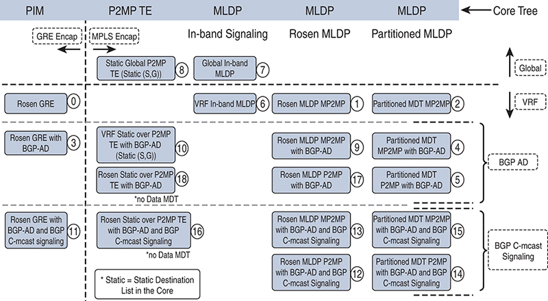
Figure 3-11 MPLS Profiles
When you’re determining which profile to implement, you first need to think about which operating systems are being used in the network. It all boils down to the least common denominator. For example, if you are using NX-OS in your network, you are limited to Profile 0, and the decision is easy. Table 3-1 provides details on the profiles supported in each operating system as of this writing. You can also see the current version of the release notes to verify support of your specific hardware and software platforms.
Table 3-1 MVPN Operating System Support Matrix
Profile |
NX-OS |
IOS-XE |
IOS-XR |
0 |
IPv4 only |
X |
X |
1 |
X |
X |
|
2 |
X |
||
3 |
X |
||
4 |
X |
||
5 |
X |
||
X |
X |
||
7 |
X |
X |
|
8 |
X |
X |
|
9 |
X |
X |
|
10 |
X |
||
11 |
X |
X |
|
12 |
X |
X |
|
13 |
X |
X |
|
14 |
X |
X |
|
15 |
X |
||
16 |
X |
||
17 |
X |
X |
|
18 |
X |
||
19 |
X |
||
20 |
X |
||
21 |
X |
||
22 |
X |
||
23 |
X |
||
24 |
X |
||
25 |
X |
||
26 |
X |
Next, you need to determine what you need to accomplish and the available resources. Items to consider include the following:
![]() Core and customer multicast requirements
Core and customer multicast requirements
![]() Scalability—that is, how many core and customer routes will be needed
Scalability—that is, how many core and customer routes will be needed
![]() Hardware limitations
Hardware limitations
![]() Operational experience, which may determine which requirements you can support
Operational experience, which may determine which requirements you can support
![]() High-availability requirements
High-availability requirements
If one of your requirements is high availability, consider using a profile that supports MLDP. With this implementation, you can take advantage of Loop-Free Alternate (LFA) routing and minimize the complexity of traffic engineering tunnels.
After you have made a decision on which profile to implement, you should build a lab and test, test, test to become familiar with the operation and troubleshooting of your particular environment.
Migrating Between Profiles
With IOS-XE, you can configure support for multiple profiles within the address family of the VRF definition. In Example 3-56, both Profile 0 and Profile 1 are supported simultaneously, but Profile 0 is preferred unless the mdt preference mldp command is configured, in which case Profile 1 is selected. Using two profiles at once certainly helps to ease the migration from some profiles, but the capabilities are limited.
Example 3-56 Migrating Between Profiles Using IOS-XE
vrf definition RED
 rd 65000:1
 vpn id 65000:1
 !
 address-family ipv4
  mdt preference mldp
  mdt default mpls mldp 192.168.0.8
  mdt default mpls mldp 192.168.0.9
  mdt default 232.0.0.1
  mdt data 232.0.1.0 0.0.0.255 threshold 2
  mdt data threshold 2
 exit-address-family
IOS-XR, on the other hand, allows you to map individual flows to a unique profile by using route policy language (RPL). This is a very powerful feature, as shown in Example 3-57.
Example 3-57 Migrating Between Profiles Using IOS-XR and RPL
RP/0/0/CPU0:R4#
route-policy MCast-Policy-RED
  if source in (172.16.12.20/32) then
    set core-tree pim-default
  endif
  if destination in (224.1.3.0/24) then
    set core-tree mldp
  else
    set core-tree mldp-partitioned-mp2mp
  endif
end-policy
In the command set shown in Example 3-57, the first if statement looks at the source address. A match to 172.16.12.20 means Profile 0, or data MDT with GRE, is used. The second if statement looks for a destination match. If the destination multicast address falls in the subnet range 224.1.3.0/24, MLDP, or Profile 1, is used. The final else statement is a catch-all that means the partitioned MLDP, or Profile 2, is used. The capabilities are almost endless.
Be sure to apply the statement as shown in Example 3-58.
Example 3-58 Applying Profiles Using IOS-XR and RPL
router pim
 vrf RED
  address-family ipv4
   rpf topology route-policy MCast-Policy-RED
Provider (P) Multicast Transport
Transporting multicast traffic flows across the provider network is accomplished using any one of or a combination of these three methods:
![]() PIM: With PIM in the core, customer multicast messages are mapped to provider multicast messages using IP in IP with a GRE header, as shown in Example 3-3 with Profile 0.
PIM: With PIM in the core, customer multicast messages are mapped to provider multicast messages using IP in IP with a GRE header, as shown in Example 3-3 with Profile 0.
![]() MLDP: Both P2MP and MP2MP transport are supported.
MLDP: Both P2MP and MP2MP transport are supported.
![]() TE tunnels: Profiles 8, 10, and 18 use traffic engineering (TE) tunnels. Profile 8 is unique in that it does not send traffic through a VPN but rather uses the global routing table.
TE tunnels: Profiles 8, 10, and 18 use traffic engineering (TE) tunnels. Profile 8 is unique in that it does not send traffic through a VPN but rather uses the global routing table.
PE–CE Multicast Routing
Multicast routing between multiple customer (C) locations requires the integration of the provider edge (PE) and customer edge (CE) equipment. The universal requirement is to have PIM enabled and functional between the PE and the CE, as shown in Figure 3-12.
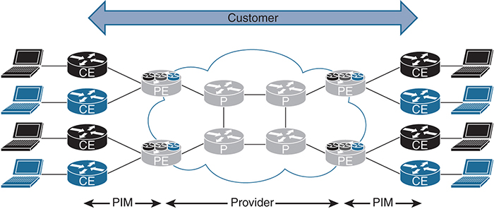
Previous examples in this chapter use PIM-SM or Any-Source Multicast (ASM) on the customer network. The integration between the PE and the CE means that the provider network is an extension of the customer network. For example, if a CE router is used as the RP, any source or receiver would register with the RP over the provider network, and only one RP is required for the entire VPN. The propagation of (*, G) or (S, G) multicast messages is handled “transparently” from the customer’s perspective.
CE–CE Multicast Routing
With ASM, an RP is required. The placement of the RP and how it is connected does provide some options. In previous examples, one of the CE devices was configured as an RP for the entire VPN, but there are two more options. The first option is to use a PE device as the RP (in the case of a self-managed MPLS solution). High availability can be configured using Anycast RP. The second solution is to build an RP at each CE location and connect the RPs using MSDP. This solution adds a tremendous amount of configuration overhead. It would be a good choice if the environment has an SP-managed MPLS Layer 3 VPN solution.
PE–PE Ingress Replication
PE–PE ingress replication enables you to create a P2MP tree where ingress devices replicate the multicast packets, encapsulate the packets in a unicast tunnel, and send the packets to egress devices. PE–PE ingress replication is a great tool to have in the toolbox, but it’s not one that should be used all the time or even very often. PE–PE ingress replication works well when the core of the network does not support any type of multicast routing. For example, you might have equipment in the core that will not support multicast, or you may be integrating with another provider that does not allow multicast. Whatever the reason, PE–PE ingress replication is a workaround solution, and using it really defeats the purpose of multicast in the first place because it involves converting multicast streams to unicast so they can be propagated over the core network.
In Figure 3-13, the PE router in the top-right corner of the diagram is receiving multicast traffic from the sender, converting it into two unicast flows, and sending it across the network.
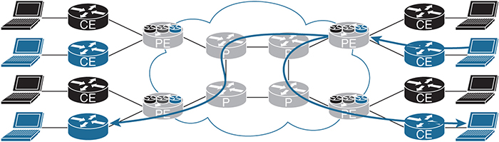
Figure 3-13 PE–PE Ingress Replication
At the time of this writing, the Cisco CSR 1000v is the only IOS-XE device that supports ingress replication. (This topic is explained in detail in Chapter 2, “Multicast Scalability and Transport Diversification.”) With IOS-XR, you have the capability to configure PE–PE ingress replication. Example 3-59 is a configuration snippet.
Example 3-59 PE–PE Ingress Replication Using IOS-XR
RP/0/0/CPU0:R4#
route-policy IR-Default
  set core-tree ingress-replication-default
end-policy

multicast-routing
 !
 vrf BLU
  address-family ipv4
   interface all enable
   bgp auto-discovery ingress-replication
   !
   mdt default ingress-replication
   mdt data ingress-replication

router pim
!
 vrf BLU
  address-family ipv4
   rpf topology route-policy IR-Default
   mdt c-multicast-routing bgp
   !
   !
  !
 !
You can look at the MRIB table by using the show mrib vrf BLU route 224.2.2.22 command. The interface list in Example 3-60 shows IRmdtBLU, which indicates that it is using ingress replication.
Example 3-60 IRmdtBLU Ingress Replication Using IOS-XR
RP/0/0/CPU0:R4# show mrib vrf BLU route 224.2.2.22
Fri Feb 24 23:08:26.136 UTC

IP Multicast Routing Information Base
Entry flags: L - Domain-Local Source, E - External Source to the Domain,
    C - Directly-Connected Check, S - Signal, IA - Inherit Accept,
    IF - Inherit From, D - Drop, ME - MDT Encap, EID - Encap ID,
    MD - MDT Decap, MT - MDT Threshold Crossed, MH - MDT interface handle
    CD - Conditional Decap, MPLS - MPLS Decap, EX - Extranet
    MoFE - MoFRR Enabled, MoFS - MoFRR State, MoFP - MoFRR Primary
    MoFB - MoFRR Backup, RPFID - RPF ID Set, X - VXLAN
Interface flags: F - Forward, A - Accept, IC - Internal Copy,
    NS - Negate Signal, DP - Don't Preserve, SP - Signal Present,
    II - Internal Interest, ID - Internal Disinterest, LI - Local Interest,
    LD - Local Disinterest, DI - Decapsulation Interface
    EI - Encapsulation Interface, MI - MDT Interface, LVIF - MPLS Encap,
    EX - Extranet, A2 - Secondary Accept, MT - MDT Threshold Crossed,
    MA - Data MDT Assigned, LMI - mLDP MDT Interface, TMI - P2MP-TE MDT Interface
    IRMI - IR MDT Interface

(172.19.14.22,224.2.2.22) RPF nbr: 172.19.4.4 Flags: RPF
  Up: 00:02:06
  Incoming Interface List
    IRmdtBLU Flags: A IRMI, Up: 00:02:06
To verify the PE devices that are participating in the BLU MVPN, you use the show mvpn vrf BLU pe command, as shown in Example 3-61.
Example 3-61 MVPN VRF PEs Using IOS-XR
RP/0/0/CPU0:R4# show mvpn vrf BLU pe
Sat Feb 25 23:03:16.548 UTC

MVPN Provider Edge Router information

VRF : BLU

PE Address : 192.168.0.3 (0x12be134c)
  RD: 65000:2 (valid), RIB_HLI 0, RPF-ID 9, Remote RPF-ID 0, State: 1, S-PMSI: 0
  PPMP_LABEL: 0, MS_PMSI_HLI: 0x00000, Bidir_PMSI_HLI: 0x00000, MLDP-added:  [RD 0, ID 0, Bidir ID 0, Remote Bidir ID 0], Counts(SHR/SRC/DM/DEF-MD): 0, 1, 0, 0, Bidir: GRE RP Count 0, MPLS RP Count 0RSVP-TE added: [Leg 0, Ctrl Leg 0, Part tail 0 Def Tail 0, IR added: [Def Leg 0, Ctrl Leg 0, Part Leg 0, Part tail 0, Part IR Tail Label 0
  bgp_i_pmsi: 0,0/0 , bgp_ms_pmsi/Leaf-ad: 0/0, bgp_bidir_pmsi: 0, remote_bgp_bidir_pmsi: 0, PMSIs: I 0x0, 0x0, MS 0x0, Bidir Local: 0x0, Remote: 0x0, BSR/Leaf-ad 0x0/0, Autorp-disc/Leaf-ad 0x0/0, Autorp-ann/Leaf-ad 0x0/0
 IIDs: I/6: 0x0/0x0, B/R: 0x0/0x0, MS: 0x0, B/A/A: 0x0/0x0/0x0

  Bidir RPF-ID: 10, Remote Bidir RPF-ID: 0
  I-PMSI:  (0x0)
  I-PMSI rem:  (0x0)
  MS-PMSI:  (0x0)
  Bidir-PMSI:  (0x0)
  Remote Bidir-PMSI:  (0x0)
  BSR-PMSI:  (0x0)
  A-Disc-PMSI:  (0x0)
  A-Ann-PMSI:  (0x0)
  RIB Dependency List: 0x121696a4
  Bidir RIB Dependency List: 0x0
    Sources: 1, RPs: 0, Bidir RPs: 0

PE Address : 192.168.0.5 (0x12c9f7a0)
  RD: 0:0:0 (null), RIB_HLI 0, RPF-ID 11, Remote RPF-ID 0, State: 0, S-PMSI: 0
  PPMP_LABEL: 0, MS_PMSI_HLI: 0x00000, Bidir_PMSI_HLI: 0x00000, MLDP-added:  [RD 0, ID 0, Bidir ID 0, Remote Bidir ID 0], Counts(SHR/SRC/DM/DEF-MD): 0, 0, 0,  0, Bidir: GRE RP Count 0, MPLS RP Count 0RSVP-TE added: [Leg 0, Ctrl Leg 0,  Part tail 0 Def Tail 0, IR added: [Def Leg 0, Ctrl Leg 0, Part Leg 0, Part tail 0, Part IR Tail Label 0
  bgp_i_pmsi: 1,0/0 , bgp_ms_pmsi/Leaf-ad: 0/0, bgp_bidir_pmsi: 0, remote_bgp_bidir_pmsi: 0, PMSIs: I 0x12897d48, 0x0, MS 0x0, Bidir Local: 0x0, Remote: 0x0, BSR/Leaf-ad 0x0/0, Autorp-disc/Leaf-ad 0x0/0, Autorp-ann/Leaf-ad 0x0/0
 IIDs: I/6: 0x1/0x0, B/R: 0x0/0x0, MS: 0x0, B/A/A: 0x0/0x0/0x0

  Bidir RPF-ID: 12, Remote Bidir RPF-ID: 0
 I-PMSI:   Unknown/None (0x12897d48)


  I-PMSI rem:  (0x0)
  MS-PMSI:  (0x0)
  Bidir-PMSI:  (0x0)
  Remote Bidir-PMSI:  (0x0)
  BSR-PMSI:  (0x0)
  A-Disc-PMSI:  (0x0)
  A-Ann-PMSI:  (0x0)
 RIB Dependency List: 0x0
  Bidir RIB Dependency List: 0x0
    Sources: 0, RPs: 0, Bidir RPs: 0
PE Address : 192.168.0.6 (0x12be86e0)
  RD: 0:0:0 (null), RIB_HLI 0, RPF-ID 1, Remote RPF-ID 0, State: 0, S-PMSI: 0
  PPMP_LABEL: 0, MS_PMSI_HLI: 0x00000, Bidir_PMSI_HLI: 0x00000, MLDP-added: [RD 0, ID 0, Bidir ID 0, Remote Bidir ID 0], Counts(SHR/SRC/DM/DEF-MD): 0, 0, 0, 0, Bidir: GRE RP Count 0, MPLS RP Count 0RSVP-TE added: [Leg 0, Ctrl Leg 0, Part tail 0 Def Tail 0, IR added: [Def Leg 1, Ctrl Leg 0, Part Leg 0, Part tail 0, Part IR Tail Label 0
  bgp_i_pmsi: 1,0/0 , bgp_ms_pmsi/Leaf-ad: 0/0, bgp_bidir_pmsi: 0, remote_bgp_bidir_pmsi: 0, PMSIs: I 0x12b06580, 0x0, MS 0x0, Bidir Local: 0x0, Remote: 0x0, BSR/Leaf-ad 0x0/0, Autorp-disc/Leaf-ad 0x0/0, Autorp-ann/Leaf-ad 0x0/0
 IIDs: I/6: 0x1/0x0, B/R: 0x0/0x0, MS: 0x0, B/A/A: 0x0/0x0/0x0

  Bidir RPF-ID: 2, Remote Bidir RPF-ID: 0
  I-PMSI:  (0x12b06580)
  I-PMSI rem:  (0x0)
  MS-PMSI:  (0x0)
  Bidir-PMSI:  (0x0)
  Remote Bidir-PMSI:  (0x0)
  BSR-PMSI:  (0x0)
  A-Disc-PMSI:  (0x0)
  A-Ann-PMSI:  (0x0)
  RIB Dependency List: 0x0
  Bidir RIB Dependency List: 0x0
    Sources: 0, RPs: 0, Bidir RPs: 0
The highlighted IP addresses in Example 3-61 are the PEs that are participating in the BLU VPN.
One final command in Example 3-62, show mvpn vrf BLU ipv4 database ingress-replication, shows the PEs that have valid receivers and the unique labels associated with each of them.
Example 3-62 MVPN VRF Valid Receivers Using IOS-XR
RP/0/0/CPU0:R4# show mvpn vrf BLU ipv4 database ingress-replication
Sun Feb 26 20:14:25.693 UTC
Tunnel/MDT Type            Core        Head Local      Leg     Head
Label                     Source         Label        Count   LSM-ID

Default IR MDT          192.168.0.4      24028          2     0x80001
   I-PMSI Leg(out label):  192.168.0.5(24024)
                           192.168.0.6(24023)
Partition IR MDT            0.0.0.0          0          0     0x0
Control IR MDT              0.0.0.0          0          0     0x0
Multicast Extranet VPNs
Most service providers do not generally allow multicast from one customer network into another customer network. An extranet VPN or inter-VRF multicast is useful when a customer is deploying a self-managed MPLS VPN network. This feature allows multicast messages to flow from one VRF to another. An example of a use case is a customer that has a VPN for video cameras and wants to protect those resources from attack by placing them into a unique VPN, but it wants other departments, groups, or organizations to be able to view multicast video streams from the cameras. Several options can be used, including the following:
![]() Route leaking
Route leaking
![]() VRF fallback
VRF fallback
![]() VRF select
VRF select
![]() Fusion router
Fusion router
![]() VRF-Aware Service Infrastructure (VASI)
VRF-Aware Service Infrastructure (VASI)
Route Leaking
Although route leaking is a possible solution, it not one that is recommended. With route leaking, routes from one VRF are imported/exported into another VRF, as shown in Figure 3-14.
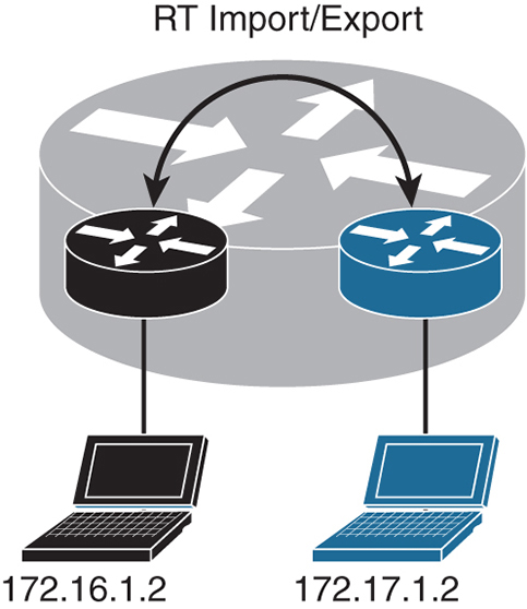
Figure 3-14 Route Leaking
The configuration for route leaking using IOS-XR is shown in Example 3-63.
Example 3-63 Route Leaking Using IOS-XR
vrf BLU
 address-family ipv4 unicast
  import route-target
   65000:1
   65000:2
  !
  export route-target
   65000:1
   65000:2
  !
 !
vrf RED
 address-family ipv4 unicast
  import route-target
   65000:1
   65000:2
  !
  export route-target
   65000:1
   65000:2

router bgp 65000
 bgp router-id 192.168.0.4
 address-family ipv4 unicast
 !
 address-family ipv4 multicast
!
 address-family vpnv4 unicast
 !
 address-family ipv6 unicast
 !
 address-family vpnv6 unicast
 !
 address-family ipv4 mdt
 !
 session-group AS65000
  remote-as 65000
  update-source Loopback0
 !
 neighbor-group AS65000
  use session-group AS65000
  address-family ipv4 unicast
   route-policy ALLOW-ALL in
   route-policy ALLOW-ALL out
  !
  address-family ipv4 multicast
   route-policy ALLOW-ALL in
   route-policy ALLOW-ALL out
  !
  address-family vpnv4 unicast
   route-policy ALLOW-ALL in
   route-policy ALLOW-ALL out
  !
  address-family ipv6 unicast
   route-policy ALLOW-ALL in
   route-policy ALLOW-ALL out
  !
  address-family vpnv6 unicast
   route-policy ALLOW-ALL in
   route-policy ALLOW-ALL out
  !
  address-family ipv4 mdt
   route-policy ALLOW-ALL in
   route-policy ALLOW-ALL out
  !
 !

multicast-routing
 !
vrf BLU
  address-family ipv4
   mdt source Loopback0
   interface all enable
   mdt default ipv4 232.0.0.2
   mdt data 232.0.2.0/24 threshold 2
 !
 vrf RED
  address-family ipv4
   mdt source Loopback0
   interface all enable
   mdt default ipv4 232.0.0.1
   mdt data 232.0.1.0/24 threshold 2
  !
 !
!

router pim
 !
 vrf BLU
  address-family ipv4
   interface GigabitEthernet0/0/0/1
   !
  !
 !
 vrf RED
  address-family ipv4
   !
   interface GigabitEthernet0/0/0/2
   !
  !
 !
!
The primary challenge with this solution is that you have limited control over the traffic flow, and it works only if you do not have overlapping address space. You are essentially making one VRF instance out of two, and this completely invalidates the need for multiple VRF instances.
VRF Fallback
When all else fails, you can use a static route! VRF fallback gives you the ability to configure a static multicast route that directs multicast messages to another VRF or the global routing table. As shown in Figure 3-15, there are three VRF instances: SVCS, RED, and BLU. The RP is in the SVCS VRF with IP address 10.0.0.5, and you want the RED and BLU VRF instances to be able to access the sender in the SVCS VRF.

Figure 3-15 VRF Fallback
Example 3-64 shows the IOS-XE commands used to configure VRF fallback.
Example 3-64 VRF Fallback Using IOS-XE
vrf definition BLU
 address-family ipv4
!
vrf definition RED
 address-family ipv4
!
vrf definition SVCS
 address-family ipv4
!
interface Ethernet0/0
 vrf forwarding SVCS
 ip address 10.0.0.2 255.255.255.0
 ip pim sparse-mode
!
interface Ethernet0/1
 vrf forwarding BLU
 ip address 172.17.2.2 255.255.255.0
 ip pim sparse-mode
!
interface Ethernet0/2
vrf forwarding RED
 ip address 172.16.2.2 255.255.255.0
 ip pim sparse-mode
!
ip multicast-routing vrf BLU
ip multicast-routing vrf RED
ip multicast-routing vrf SVCS
ip pim vrf BLU rp-address 10.0.0.5
ip pim vrf RED rp-address 10.0.0.5
ip pim vrf SVCS rp-address 10.0.0.5
ip mroute vrf BLU 10.0.0.0 255.255.255.0 fallback-lookup vrf SVCS
ip mroute vrf RED 10.0.0.0 255.255.255.0 fallback-lookup vrf SVCS
Using the show ip mroute vrf SVCS 224.1.1.1 command, you can verify the extranet receivers in the RED and BLU VRF instances, as shown in Example 3-65.
Example 3-65 VRF Fallback Verification Using IOS-XE
S1# show ip mroute vrf SVCS 224.1.1.1
IP Multicast Routing Table
Flags: D - Dense, S - Sparse, B - Bidir Group, s - SSM Group, C - Connected,
       L - Local, P - Pruned, R - RP-bit set, F - Register flag,
       T - SPT-bit set, J - Join SPT, M - MSDP created entry, E - Extranet,
       X - Proxy Join Timer Running, A - Candidate for MSDP Advertisement,
       U - URD, I - Received Source Specific Host Report,
       Z - Multicast Tunnel, z - MDT-data group sender,
       Y - Joined MDT-data group, y - Sending to MDT-data group,
       V - RD & Vector, v - Vector
Outgoing interface flags: H - Hardware switched, A - Assert winner
 Timers: Uptime/Expires
 Interface state: Interface, Next-Hop or VCD, State/Mode
(*, 224.1.1.1), 00:10:24/stopped, RP 10.0.0.5, flags: SJCE
  Incoming interface: Ethernet0/0, RPF nbr 10.0.0.5
  Outgoing interface list: Null
  Extranet receivers in vrf BLU:
(*, 224.1.1.1), 00:10:58/stopped, RP 10.0.0.5, OIF count: 1, flags: SJC
  Extranet receivers in vrf RED:
(*, 224.1.1.1), 00:10:48/stopped, RP 10.0.0.5, OIF count: 1, flags: SJC
(10.0.0.1, 224.1.1.1), 00:10:24/00:02:24, flags: TE
  Incoming interface: Ethernet0/0, RPF nbr 0.0.0.0
  Outgoing interface list: Null
  Extranet receivers in vrf BLU:
  (10.0.0.1, 224.1.1.1), 00:02:58/stopped, OIF count: 1, flags: T
  Extranet receivers in vrf RED:
  (10.0.0.1, 224.1.1.1), 00:08:39/stopped, OIF count: 1, flags: T
The show ip mroute vrf RED 224.1.1.1 and the show ip mroute vrf BLU 224.1.1.1 commands in Example 3-66 both show the incoming interface as Ethernet0/0, which is from VRF SVCS.
Example 3-66 VRF Fallback Interface Using IOS-XE
S1# show ip mroute vrf RED 224.1.1.1
IP Multicast Routing Table
Outgoing interface flags: H - Hardware switched, A - Assert winner
 Timers: Uptime/Expires
 Interface state: Interface, Next-Hop or VCD, State/Mode
(*, 224.1.1.1), 00:15:42/stopped, RP 10.0.0.5, flags: SJC
  Incoming interface: Ethernet0/0, RPF nbr 10.0.0.5, using vrf SVCS
  Outgoing interface list:
    Ethernet0/2, Forward/Sparse, 00:14:48/00:03:25
(10.0.0.1, 224.1.1.1), 00:02:43/stopped, flags: T
  Incoming interface: Ethernet0/0, RPF nbr 0.0.0.0, using vrf SVCS
  Outgoing interface list:
    Ethernet0/2, Forward/Sparse, 00:02:43/00:03:25

S1# show ip mroute vrf BLU 224.1.1.1
IP Multicast Routing Table
Outgoing interface flags: H - Hardware switched, A - Assert winner
 Timers: Uptime/Expires
 Interface state: Interface, Next-Hop or VCD, State/Mode
(*, 224.1.1.1), 00:15:57/stopped, RP 10.0.0.5, flags: SJC
  Incoming interface: Ethernet0/0, RPF nbr 10.0.0.5, using vrf SVCS
  Outgoing interface list:
    Ethernet0/1, Forward/Sparse, 00:15:02/00:03:11
(10.0.0.1, 224.1.1.1), 00:03:03/stopped, flags: T
  Incoming interface: Ethernet0/0, RPF nbr 0.0.0.0, using vrf SVCS
  Outgoing interface list:
    Ethernet0/1, Forward/Sparse, 00:03:03/00:03:11
Finally, the show ip rpf vrf RED 10.0.0.1 and show ip rpf vrf BLU 10.0.0.1 commands show that the extranet RPF rule is in use, as indicated by the highlighted output in Example 3-67.
Example 3-67 Extranet RPF Rule Using IOS-XE
S1# show ip rpf vrf RED 10.0.0.1
RPF information for ? (10.0.0.1)
  RPF interface: Ethernet0/0
  RPF neighbor: ? (10.0.0.1) - directly connected
  RPF route/mask: 10.0.0.0/24
  RPF type: multicast (connected)
  Doing distance-preferred lookups across tables
  Using Extranet RPF Rule: Static Fallback Lookup, RPF VRF: SVCS
  RPF topology: ipv4 multicast base

S1# show ip rpf vrf BLU 10.0.0.1
RPF information for ? (10.0.0.1)
  RPF interface: Ethernet0/0
  RPF neighbor: ? (10.0.0.1) - directly connected
  RPF route/mask: 10.0.0.0/24
  RPF type: multicast (connected)
  Doing distance-preferred lookups across tables
  Using Extranet RPF Rule: Static Fallback Lookup, RPF VRF: SVCS
  RPF topology: ipv4 multicast base
VRF Select
The VRF select feature is similar to VRF fallback except that with VRF select, the multicast address can be specified. This feature provides additional security because you can easily limit the multicast groups. The IOS-XE configuration is shown in Example 3-68.
Example 3-68 VRF Select Using IOS-XE
ip mroute vrf BLU 10.0.0.0 255.255.255.0 fallback-lookup vrf SVCS
ip mroute vrf RED 10.0.0.0 255.255.255.0 fallback-lookup vrf SVCS
ip multicast vrf BLU rpf select vrf SVCS group-list 1
ip multicast vrf RED rpf select vrf SVCS group-list 1
!
access-list 1 permit 224.1.1.1
Using the show ip mroute vrf SVCS 224.1.1.1 command, validate the extranet receivers in the RED and BLU VRF instances, as shown in Example 3-69.
Example 3-69 VRF Select Validation Using IOS-XE
S1# show ip mroute vrf SVCS 224.1.1.1
IP Multicast Routing Table
Outgoing interface flags: H - Hardware switched, A - Assert winner
 Timers: Uptime/Expires
 Interface state: Interface, Next-Hop or VCD, State/Mode
(*, 224.1.1.1), 00:20:42/stopped, RP 10.0.0.5, flags: SJCE
Incoming interface: Ethernet0/0, RPF nbr 10.0.0.5
  Outgoing interface list: Null
  Extranet receivers in vrf BLU:
(*, 224.1.1.1), 01:08:40/stopped, RP 10.0.0.5, OIF count: 1, flags: SJC
  Extranet receivers in vrf RED:
(*, 224.1.1.1), 01:08:31/stopped, RP 10.0.0.5, OIF count: 1, flags: SJC
(10.0.0.1, 224.1.1.1), 00:20:42/00:02:03, flags: TE
  Incoming interface: Ethernet0/0, RPF nbr 0.0.0.0
  Outgoing interface list: Null
  Extranet receivers in vrf BLU:
  (10.0.0.1, 224.1.1.1), 00:15:15/stopped, OIF count: 1, flags: T
  Extranet receivers in vrf RED:
  (10.0.0.1, 224.1.1.1), 00:55:31/stopped, OIF count: 1, flags: T
Fusion Router
A fusion router acts as a fusion or connector point for multiple VPNs. It is fundamentally an L3 device where all VPNs connect. This design has several benefits, such as better control of routing and multicast routing and the ability to perform Network Address Translation (NAT) functionality in the event of overlapping IP addresses. In addition, a fusion router can act as a central RP for all the VPNs, as shown in Figure 3-16.
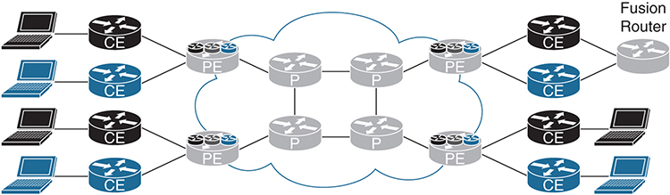
Figure 3-16 Fusion Router
Additional fusion routers configured as the RP can be used for a high availability solution. By assigning the RP functionality to a loopback address, you can implement the Anycast RP model for high availability.
Many customers choose to implement firewalls between the edge CE and the firewall for additional protection and inspection of traffic. Depending on the capabilities of the firewall, you may consider implementing fusion routers in transparent or L2 mode to minimize the impact on multicast control plane traffic and multicast flows, as shown in Figure 3-17.

Figure 3-17 Fusion Router with Firewalls
VRF-Aware Service Infrastructure (VASI)
VASI is essentially a software cable that connects VRF instances. It supports NAT, firewalling, IPsec, IPv4, IPv6, multiple routing protocols, and IPv4 and IPv6 multicast. This design is very similar to the fusion routers concept except that the CE routing and fusion capability happens all in the same device, as shown in Figure 3-18.
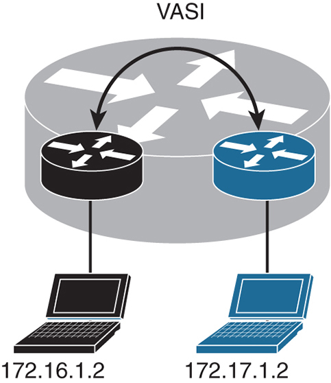
Configuring VASI is a simple task, as shown in Example 3-70.
Example 3-70 VASI Configuration Using IOS-XE
vrf definition BLU
 address-family ipv4
!
vrf definition RED
 address-family ipv4
!
interface GigabitEthernet0/0/0
 vrf forwarding RED
 ip address 172.16.1.1 255.255.255.0
!
interface GigabitEthernet0/0/1
 vrf forwarding BLU
 ip address 172.17.1.1 255.255.255.0
!
interface vasileft1
 vrf forwarding RED
 ip address 192.168.0.1 255.255.255.0
!
interface vasiright1
 vrf forwarding BLU
 ip address 192.168.0.2 255.255.255.0
!
ip route vrf BLU 172.16.0.0 255.255.0.0 vasiright1
ip route vrf RED 172.17.0.0 255.255.0.0 vasileft1
In this example, VRF RED connects to vasileft1, and VRF BLU connect to vasiright1, essentially building a logical wire between the RED and BLU VRF instances. Additional features and functionality can now be applied to the VASI interface to meet security, NAT, or other requirements.
IPv6 MVPN
Fortunately, making the transition to IPv6 is easy when comes to MVPNs. Most of the features and functionality you have already learned about in this chapter apply to IPv6. (Check the latest documentation for current feature support.)
Just as you would enable address families for IPv4, you can do this for IPv6, as shown in the following snippet from IOS-XR:
address-family ipv6 unicast
!
address-family vpnv6 unicast
!
address-family ipv4 mvpn
!
address-family ipv6 mvpn
Bit Index Explicit Replication (BIER)
BIER is a new development in multicast transport. It does not require any of the traditional methods of tree building and takes an innovative approach to propagating multicast messages. When a multicast data packet enters the domain, the ingress router determines the set of egress routers to which the packet needs to be sent. The ingress router encapsulates the packet in a BIER header, which contains a bitstring in which each bit represents exactly one egress router in the domain; to forward the packet to a given set of egress routers, the bits corresponding to those routers are set in the BIER header. The multicast forwarding state is created using link-state protocols such as OSPF or IS-IS. Each bit-forwarding router (BFR) is identified as a single bit in the BIER header. When a message is to be sent to multiple BIER nodes, the bits in the bitstring that identifies those particular nodes are set by the ingress BIER node. As the BIER message moves through the network, the packet can be replicated out multiple interfaces by a BIER node to maintain the shortest path to the destination. In an MPLS environment, BIER labels are assigned to MPLS labels; this is called BIER MPLS. The BIER solution eliminates the per-flow state and the explicit tree-building protocols, which results in considerable simplification.
BIER addresses the problems associated with current multicast solutions reviewed earlier in this chapter:
![]() Explicit tree building protocols are the core of multicast transport. The tree-building process requires memory to build up state in every node in the routing domains. This also impacts multicast convergence in the large routing domain.
Explicit tree building protocols are the core of multicast transport. The tree-building process requires memory to build up state in every node in the routing domains. This also impacts multicast convergence in the large routing domain.
![]() Using RPF to build the trees toward the root could result in different paths between the same endpoints in a topology with multiple paths.
Using RPF to build the trees toward the root could result in different paths between the same endpoints in a topology with multiple paths.
![]() Control plane aggregation of the flows is not possible in the current multicast solutions. Optimal delivery for every flow has two states maintained in the RIB.
Control plane aggregation of the flows is not possible in the current multicast solutions. Optimal delivery for every flow has two states maintained in the RIB.
![]() Maintaining and troubleshooting multicast networks can be very difficult. The need to understand the multicast control plane that overlays the unicast control plane increases the operational overhead for solution management.
Maintaining and troubleshooting multicast networks can be very difficult. The need to understand the multicast control plane that overlays the unicast control plane increases the operational overhead for solution management.
The BIER concept is as follows:
Step 1. The router assigns a unique bit position mask to each router in the domain.
Step 2. Each edge router floods the bit position to ID mapping within IGP (OSPF or IS-IS). A new LSA type is used to exchange this new information.
Step 3. All the routers in the unicast domain for BIER calculate the best path for each of the BFR indexes. In addition, the bit positions are OR’d (Boolean function) for the bitmask for each BFR neighbor. This constitutes the bit forwarding table.
Step 4. The multicast packets are forwarded based on the bit forwarding table using a logical AND operation of the multicast flow bit.
The bit index table is tied to ECMP for multiple paths from each node, where applicable. The ECMP paths taking parallel interfaces to a single neighbor are noted as a single bitmask. If the ECMP for multiple paths is seen for different neighbors, it is noted as a separate bitmask. BIER also has a concept of sets, whereby you can group a set of routers in a single group (similar to an area). The forwarding behavior is based on the packets’ set ID, as illustrated in Figure 3-19.
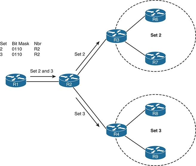
The receiver information (egress router for multicast flow) is learned via an overlay mechanism. The current deployment of BIER in IOS-XR is via BGP overlay for receiver learning. Once the receiver is known within the domain, the forwarding is simple, using the bitmask index. This is different from PIM domains, where the forwarding and signaling are maintained in the multicast state table at the same time. In BIER, multicast forwarding is kept separate from the signaling.
Figure 3-20 provides a high-level overview of packet flow in BIER:

Figure 3-20 Multicast Forwarding of Packets in BIER
![]() Before the multicast exchange, all the routers in the BIER domain exchange bitmask information by using IGP (OSPF in this case). All the routers in the unicast domain for BIER calculate the best path for each of the BFR indexes.
Before the multicast exchange, all the routers in the BIER domain exchange bitmask information by using IGP (OSPF in this case). All the routers in the unicast domain for BIER calculate the best path for each of the BFR indexes.
![]() The overlay control plane (in this case BGP) transmits the receiver information and the BIER nodes in the domain, as in the step above.
The overlay control plane (in this case BGP) transmits the receiver information and the BIER nodes in the domain, as in the step above.
![]() The multicast data plane from the source connected to R1 is propagated to R4 through the bit index Boolean AND function, as in steps 2 through 4.
The multicast data plane from the source connected to R1 is propagated to R4 through the bit index Boolean AND function, as in steps 2 through 4.
BIER, which is relatively new, is available only in IOS-XR at this writing. With this innovative solution, there is no need for an explicit multicast signaling protocol in the network. With BIER there is no need to run PIM, MLDP, or P2MP MPLS traffic engineering in the network to signal multicast state at every router in the multicast domain. With BIER, the multicast forwarding state created in the network is driven by advertisements through the link state protocols OSPF or IS-IS. This forwarding state is not per (*, G) or (S, G), but per egress router. Each egress router for multicast is identified by a bit index. Each BIER router must have one unique bit in a bitstring. This bitstring is also found in the multicast packets that need to be forwarded through a BIER network.
Summary
MPLS VPN has been around for many years, implemented by service providers and enterprise customers because it provides the ability to logically separate traffic using one physical infrastructure. The capability of supporting multicast in an MPLS VPN environment has been available using default MDT. As technology has evolved, so has the capability of supporting multicast in an MPLS network. Today you can still use the traditional default MDT method, but there are now also 26 other profiles to choose from—from IP/GRE encapsulation using PIM, to traffic engineering tunnels, to MLDP, to BIER.
The requirements for extranet MVPNs, or the capability of sharing multicast messages between VPNs, has also brought about development of new capabilities, such as VRF fallback, VRF select, and VASI. The combinations of solutions are almost endless, and this chapter was specifically written to provide a taste of the different solutions and capabilities. Please do not stop here; a search engine can help you make your way through the mass of information available online to continue your education.
References
“Configure mVPN Profiles Within Cisco IOS,” www.cisco.com/c/en/us/support/docs/ip/multicast/118985-configure-mcast-00.html
RFC 2365, “Administratively Scoped IP Multicast”
RFC 6037, “Cisco Systems’ Solution for Multicast in BGP/MPLS IP VPNs”
RFC 6514, “BGP Encodings and Procedures for Multicast in MPLS/BGP IP VPNs”
RFC 6516, “IPv6 Multicast VPN (MVPN) Support Using PIM Control Plane and Selective Provider Multicast Service Interface (S-PMSI) Join Messages”
RFC 7358, “Label Advertisement Discipline for LDP Forwarding Equivalence Classes (FECs)”
RFC 7441, “Encoding Multipoint LDP (mLDP) Forwarding Equivalence Classes (FECs) in the NLRI of BGP MCAST-VPN Routes”
“Encapsulating MPLS in IP or GRE,” https://tools.ietf.org/html/draft-rosen-mpls-in-ip-or-gre-00
“Encapsulation for Bit Index Explicit Replication in MPLS and non-MPLS Networks,” https://tools.ietf.org/html/draft-ietf-bier-mpls-encapsulation-06