
Chapter 1
Interdomain Routing and Internet Multicast
This chapter explains the fundamental requirements for interdomain multicast and the three pillars of interdomain design: the control plane for source identification, the control plane for receiver identification, and the downstream control plane.
Introduction to Interdomain Multicast
Applications may require support for multicasting over large and diverse networks, such as the Internet. It is possible that a sender may exist on one side of a diverse network, far away from potential receivers. Multicast receivers could exist on any network, including networks that are altogether foreign to the sender’s network, being under completely different administrative control with different policies governing multicast forwarding.
In such scenarios, there is no reasonable expectation that all Layer 3 devices in the forwarding path will share similar configurations or policies. This is certainly the reality of multicast applications that use the Internet. Therefore, additional protocols and configuration outside basic multicast transport are required to provide internetwork multicast service. Why is this the case? Aren’t large internetworks, such as the Internet, using the same Internet Protocol (IP) for multicasting? If each network is administered using different rules, how does anything on the Internet work? As discussed in the book IP Multicast, Volume 1, the de facto standard forwarding protocol for IP Multicast is Protocol Independent Multicast (PIM). If PIM is universal, why are different policies required? A brief introduction to Internet principles will answer these questions and help you understand why additional consideration is needed when designing multicast applications across internetworks.
Internet Protocol was created as a “best effort” service. Even when IP was expanded to enable the World Wide Web (WWW) and multinetwork connectivity, best effort was a universal maxim. This maxim still exists; it dictates the forwarding behavior of today’s Internet and also, therefore, that of any other large multidomain network. Best effort in this context means that as IP traffic passes from one network to the next, it is assumed that each transit network is properly configured for optimal forwarding to any appropriate destinations. There are no guarantees of optimal forwarding—or even that packets will make it to the final destination at all.
Note: The concept of best-effort forwarding is universal and applies to all IP traffic: unicast, multicast, and broadcast. This introduction briefly explores this concept, which further exposes the need for additional forwarding mechanisms for multicast traffic across diverse networks. While basic in nature, this review establishes the foundation for multicast forwarding across internetworks. An advanced understanding of unicast Internet forwarding, including the use of Border Gateway Protocol (BGP), is assumed throughout this chapter.
If you examine the Internet from a macro perspective, you see that it is essentially a mesh of connections between many disparate networks. Typically, Internet service providers (ISPs) connect to each other for transit and/or peering to provide interconnection to other service providers or customers.
End customers include all manner of connections, including homes, cellular networks, small and medium-sized businesses, research institutions, hospitals, governments, enterprise businesses, and others. Figure 1-1 shows a small, isolated example of how this interconnectivity works, using a fictional company called Mcast Enterprises.

Figure 1-1 Mcast Enterprises Interconnectivity
Each of the network entities (surrounded by an oval) shown in Figure 1-1 is known as an autonomous system (AS)—that is, a network that has administrative and operational boundaries, with clear demarcations between itself and any other network AS. Like IP addresses, autonomous systems are numbered, and the assignment of numbers is controlled by the Internet Assigned Numbers Authority (IANA). Figure 1-2 shows the previous Internet example network represented as simple AS bubbles using private autonomous system numbers (ASNs).

Figure 1-2 The Mcast Enterprises Network as a System of Connected Autonomous Systems
Note: ASNs, as defined by the IETF, are public, just like IP addresses. However, as with IP addresses, there is a private number range that is reserved for use in non-public networks. The standard 16-bit private ASN range is 64512–65535, which is defined by RFC 6996 (a 2013 update to RFC 1930). Even though Internet functions may be discussed, all numbers used in this text (for IP addressing, ASNs, and multicast group numbers) are private to prevent confusion with existing Internet services and to protect public interest.
Some routing information is shared between the interconnected ASs to provide a complete internetwork picture. Best-effort forwarding implies that as routers look up destination information and traffic transits between ASs, each AS has its own forwarding rules. To illustrate this concept, imagine that a home user is connected to ISP Red (AS 65001) and sends an IP web request to a server within Mcast Enterprises (AS 65100). The enterprise does not have a direct connection to ISP Red. Therefore, ISP Red must forward the packets to ISP Blue, and ISP Blue can then forward the traffic to the enterprise AS with the server. ISP Red knows that ISP Blue can reach the enterprise web server at address 10.10.1.100 because ISP Blue shared that routing information with all the ASs it is connected to. ISP Red does not control the network policy or functions of ISP Blue and must trust that the traffic can be successfully passed to the server. In this situation, ISP Blue acts as a transit network. Figure 1-3 illustrates this request.

Figure 1-3 Best-Effort Forwarding from One AS to Another
Some protocols are designed to make best-effort forwarding between ASs more precise. This set of protocols is maintained by the IETF, an international organization that governs all protocols related to IP forwarding, including PIM and BGP. The IETF—like the Internet—is an open society in which standards are formed collaboratively. This means there is no inherent administrative mandate placed on network operating system vendors or networks connecting to the Internet to follow protocol rules precisely or even in the same way.
This open concept is one of the more miraculous and special characteristics of the modern Internet. Networks and devices that wish to communicate across network boundaries should use IETF-compliant software and configurations. Internet routers that follow IETF protocol specifications should be able to forward IP packets to any destination on any permitted IP network in the world. This assumes that every Internet-connected router shares some protocols with its neighbors, and those protocols are properly implemented (as discussed further later in this chapter); each router updates neighbor ASs with at least a summary of the routes it knows about. This does not assume that every network is configured or administered in the same way.
For example, an AS is created using routing protocols and policies as borders and demarcation points. In fact, routing protocols are specifically built for these two purposes. Internal routing is handled by an Interior Gateway Protocol (IGP). Examples of IGPs include Open Shortest Path First (OSPF) and Intermediate System-to-Intermediate System (IS-IS). Routers use a chosen IGP on all the routed links within the AS. When routing protocols need to share information with another AS, an External Gateway Protocol (EGP) is used to provide demarcation. This allows you to use completely separate routing policies and security between ASs that might be obstructive or unnecessary for internal links.
Border Gateway Protocol version 4 (BGPv4) is the EGP that connects all Internet autonomous systems together. Figure 1-4 shows an expanded view of the Mcast Enterprises connectivity from Figure 1-3, with internal IGP connections and an EGP link with ISP Blue. Mcast Enterprises shares a single summary route for all internal links to ISP Blue via BGP.

Figure 1-4 AS Demarcation: IGP Links Using OSPF and EGP Links Using BGP
The separation between internal (IGP) and external (EGP) routes provides several important benefits. The first is protection of critical internal infrastructure from outside influence, securing the internal routing domain. Both security and routing policies can be applied to the EGP neighborship with outside networks. Another clear benefit is the ability to better engineer traffic. Best-effort forwarding may be acceptable for Internet connections and internetwork routing. However, you definitely need more finite control over internal routes. In addition, if there are multiple external links that share similar routing information, you may want to control external path selection or influence incoming path selection—without compromising internal routing fidelity. Finally, you may choose to import only specific routes from external neighbors or share only specific internal routes with outside neighbors. Selective route sharing provides administrators control over how traffic will or will not pass through each AS.
Why is all this relevant to multicast? PIM is the IETF standard for Any-Source Multicast (ASM) and Source-Specific Multicast (SSM) in IP networks. Many people refer to PIM as a multicast routing protocol. However, PIM is unlike any IGP or EGP. It is less concerned with complex route sharing policy than with building loop-free forwarding topologies or trees. PIM uses the information learned from IP unicast routing protocols to build these trees. PIM networking and neighborships have neither an internal nor an external characteristic. PIM neighborships on a single router can exist between both IGP neighbors and EGP neighbors. If multicast internetworking is required between two ASs, PIM is a requirement. Without this relationship, a tree cannot be completed.
Crossing the administrative demarcation point from one AS to another means crossing into a network operating under a completely different set of rules and with potentially limited shared unicast routing information. Even when all the routers in two different networks are using PIM for forward multicasting, forming a forwarding tree across these networks using PIM alone is virtually impossible because Reverse Path Forwarding (RPF) information will be incomplete. In addition, it is still necessary to secure and create a prescriptive control plane for IP Multicast forwarding as you enter and exit each AS. The following sections explore these concepts further and discuss how to best forward multicast application traffic across internetworks and the Internet.
What Is a Multicast Domain? A Refresher
Before we really discuss interdomain multicast forwarding, let’s clearly define the characteristics of a multicast domain. Just like the unicast routing protocols OSPF, IS-IS, and EIGRP, PIM routers have the capability to dynamically share information about multicast trees. Most networks use only one IGP routing protocol for internal route sharing and routing table building, and there are some similarities between multicast domains and unicast domains.
When an IGP network is properly designed, routers in the network have the same routes in their individual routing information base (RIB). The routes may be summarized into larger entries on some routers—even as far as having only one summary (default) route on stub routers. Often times this process is controlled by the use of configured route sharing policy. Link-state routing protocols, such as IS-IS or OSPF, can use regions or areas to achieve summarization and route selection. The routing protocol dynamically provides the necessary routing information to all the segmented routers that need the information, allowing network architects to create boundaries between various portions of a network.
The deployed IGP also has a natural physical boundary. When the interface of an IGP router is not configured to send/receive IGP information, that interface bounds the IGP. This serves the purpose of preventing internal routing information from leaking to routers that should not or do not need internal information.
As discussed earlier in this chapter, routes between two autonomous systems are shared through the use of an EGP, and BGP is the EGP of the Internet. Most administrators configure BGP to share only essential IGP-learned routes with external routers so that only internal networks meant for public access are reachable by external devices. The routing process of the IGP is kept separate and secure from external influence. For most networks, the natural boundary of the internal routing domain lies between the IGP and the EGP of the network.
Multicast networks must also have boundaries. These boundaries may be drastically different from those of the underlying unicast network. Why? It is important to remember that IP Multicast networks are overlays on the IGP network, and most network routers can have only one PIM process. PIM uses the information found in the RIB from router to router to build both a local multicast forwarding tree and a networkwide forwarding tree. Let’s quickly review how this works.
As you know, when a router forwards unicast IP traffic, it is concerned only with the destination of the packet. The router receives a packet from an upstream device, reads the IP destination from the packet header, and then makes a path selection, forwarding the packet toward the intended destination. The RIB contains the destination information for the router to make the best forwarding decision. As explained in IP Multicast, Volume 1, multicast forwarding uses this same table but completely different logic to get packets from the source to multiple receivers on multiple paths. Receivers express interest in a multicast stream (a flow of IP packets) by subscribing to a particular group address. PIM tracks these active groups and subscribed receivers. Because receivers can request the stream from nearly any location in the network, there are many possible destination paths.
The multicast router needs to build a forwarding tree that includes a root at the source of the stream and branches down any paths toward joined receivers. The branches of the tree cannot loop back to the source, or the forwarding paradigm of efficiency will be entirely broken. PIM uses the RIB to calculate the source of packets rather than the destination. Forwarding of this nature, away from a source and toward receivers, with source route verification, is called Reverse Path Forwarding (RPF).
When a multicast packet arrives at a router, the first thing the router does is perform an RPF check. The IP source of the packet header and the interface on which it was received are compared to the RIB. If the RIB contains a proper best route to the source on the same interface on which the packet was received, the RPF check is successful. PIM then forwards that packet, as long as it has a proper tree constructed (or can construct a new tree) for the destination group.
If the required entries are not in the unicast RIB and the RPF table, the router drops any multicast packets to prevent a loop. The router doesn’t just make these RPF checks independently for every packet. RPF checks are performed by the PIM process on the router, and they are also used for building the multicast forwarding tree. If a packet fails the RPF check, the interface on which the packet is received is not added to any trees for the destination group. In fact, PIM uses RPF in almost all tree-building activities.
In addition, PIM as a protocol is independent of any unicast routing protocols or unicast forwarding. Proper and efficient multicast packet forwarding is PIM’s main purpose; in other words, PIM is designed for tree building and loop prevention. As of this writing, most PIM domains run PIM Sparse-Mode (PIM–SM). A quick review of PIM–SM mechanics provides additional aid in the exploration of multicast domains.
There are two types of forwarding trees in PIM–SM: the shortest-path tree (also known as a source tree) and the shared tree. The source tree is a tree that flows from the source (the root of the tree) to the receivers (the leaves) via the shortest (most efficient) network path. You can also think of the source as a server and the receivers as clients of that server. As mentioned earlier, clients must be connected to the Layer 3 network to be included in the tree. This allows the router to see the best path between the source and the receivers.
The subscribed clients become a “group,” and, in fact, clients use a multicast group address to perform the subscription. Internet Group Management Protocol (IGMP) is the protocol that manages the client subscription process. IGMP shares the IP group subscriptions with PIM. PIM then uses those groups to build the source tree and shares the tree information with other PIM neighbors.
Note: This review is only meant to be high level as it is germane to understanding why additional protocols are required for interdomain routing. If any of these topics are more than a simple review for you, you can find a deeper study of IGMP, PIM mechanics, and tree building in additional texts, such as IP Multicast, Volume 1.
Keep in mind that there may be many locations in a network that have a receiver. Any time a router has receivers that are reached by multiple interfaces, the tree must branch, and PIM must RPF check any received sources before adding forwarding entries to the router’s Multicast Forwarding Information Base (MFIB). A source tree in a multicast forwarding table is represented by an (S, G) entry (for source, group). The (S, G) entry contains RPF information such as the interface closest to the source and the interfaces in the path of any downstream receivers.
The branches in the entry are displayed as a list of outgoing interfaces, called an outgoing interface list (OIL). This is essentially how PIM builds the source tree within the forwarding table. Neighboring PIM routers share this information with each other so that routers will independently build proper trees, both locally and across the network. Example 1-1 shows what a completed tree with incoming interfaces and OILs look like on an IOS-XE router by using the show ip mroute command.
Example 1-1 Completed Trees
R1# show ip mroute
IP Multicast Routing Table
Flags: D - Dense, S - Sparse, B - Bidir Group, s - SSM Group, C - Connected,
       L - Local, P - Pruned, R - RP-bit set, F - Register flag,
       T - SPT-bit set, J - Join SPT, M - MSDP created entry, E - Extranet,
       X - Proxy Join Timer Running, A - Candidate for MSDP Advertisement,
       U - URD, I - Received Source Specific Host Report,
       Z - Multicast Tunnel, z - MDT-data group sender,
       Y - Joined MDT-data group, y - Sending to MDT-data group,
       G - Received BGP C-Mroute, g - Sent BGP C-Mroute,
       N - Received BGP Shared-Tree Prune, n - BGP C-Mroute suppressed,
       Q - Received BGP S-A Route, q - Sent BGP S-A Route,
       V - RD & Vector, v - Vector, p - PIM Joins on route,
       x - VxLAN group
Outgoing interface flags: H - Hardware switched, A - Assert winner, p - PIM Join
 Timers: Uptime/Expires
 Interface state: Interface, Next-Hop or VCD, State/Mode

(*, 239.1.1.1), 2d01h/00:03:22, RP 192.168.100.100, flags: SJC
  Incoming interface: Ethernet2/0, RPF nbr 10.1.5.1
  Outgoing interface list:
    Ethernet0/0, Forward/Sparse, 2d01h/00:03:22

(10.1.1.1, 239.1.1.1), 00:04:53/00:02:31, flags: T
  Incoming interface: Ethernet1/0, RPF nbr 10.1.3.1
  Outgoing interface list:
    Ethernet0/0, Forward/Sparse, 00:04:53/00:03:22
It would be very difficult for every router to manage this process completely independently in a very large network, or if there were a great number of sources (which is a benefit of opting for a source tree multicast design that provides an optimal path for fast convergence). In addition, distribution of the PIM tree information could become very cumbersome to routers that are in the path of multiple source, receivers, or groups. This is especially true if sources only send packets between long intervals, consequently causing repeated table time-outs and then subsequent tree rebuilding and processing. The shared tree is the answer to this problem in the PIM–SM network, giving routers a measure of protocol efficiency.
The main function of the shared tree is to shift the initial tree-building process to a single router. The shared tree flows from this single router toward the receivers. An additional benefit of the shared tree occurs when clients are subscribed to a group but there is not yet any active source for the group. The shared tree allows each router in the path to maintain state for the receivers only so that reprocessing of the tree branches does not need to occur again when a source comes online. The central processing location of the shared tree is known as the rendezvous point (RP).
When a receiver subscribes to a group through IGMP, the PIM process on the local router records the join, and then RPF checks the receivers against the location of the RP. If the RP is not located in the same direction as the receiver, PIM creates a local tree with the RP as the root and the receiver-bound interfaces in the OIL as the leaves or branches. The shared tree is represented in the Multicast Routing Information Base (MRIB) and MFIB as a (*, G) entry. PIM shares this information with its neighbors in the direction of the RP.
When the source begins sending packets to a group, the source-connected router registers the source with the RP and forwards the packets to the RP via unicast tunneling. The RP acts as a temporary conduit to the receivers, with packets flowing down the shared tree toward the receivers from the RP. Meanwhile, the RP signals the source-connected router to begin building a source tree. PIM on the source-connected router builds the tree and then shares the (S, G) information with its neighbors. (For more on this concept, see IP Multicast, Volume 1.)
If a PIM neighbor is in the path of the multicast flow, the router joins the source tree while also sharing the information via PIM to its neighbors. Only the routers in the path must build the source tree, which improves processing efficiency. The RP is removed from any forwarding for the (S, G) once the source tree is complete, unless of course the RP happens to be in the path of the flow. (This process is very quick, taking only milliseconds on geographically small domains.) All routers in the path must use the same RP for each group in order for this to work. Each router maintains a table of group-to-RP mappings to keep RP information current. If any router in the path has a group mapping that is incongruent with that of its neighbor, the shared-tree construction fails. RP-to-group mappings are managed through either static RP configurations or through dynamic RP protocols, such as Cisco’s Auto-RP or the open standard protocol Bootstrap Router (BSR).
Figure 1-5 illustrates the differences between a source tree and the shared tree in a basic network.

Figure 1-5 Basic Source Tree versus Shared Tree
With this reminder and understanding of RPF and PIM mechanics, let’s establish that a PIM router must have three critical components to build a complete multicast forwarding tree. These three components must be present in every multicast domain and are the primary pillars of interdomain forwarding. Let’s call them the three pillars of interdomain design:
![]() The multicast control plane for source identification: The router must know a proper path to any multicast source, either from the unicast RIB or learned (either statically or dynamically) through a specific RPF exception.
The multicast control plane for source identification: The router must know a proper path to any multicast source, either from the unicast RIB or learned (either statically or dynamically) through a specific RPF exception.
![]() The multicast control plane for receiver identification: The router must know about any legitimate receivers that have joined the group and where they are located in the network.
The multicast control plane for receiver identification: The router must know about any legitimate receivers that have joined the group and where they are located in the network.
![]() The downstream multicast control plane and MRIB: The router must know when a source is actively sending packets for a given group. PIM–SM domains must also be able to build a shared tree from the local domain’s RP, even when the source has registered to a remote RP in a different domain.
The downstream multicast control plane and MRIB: The router must know when a source is actively sending packets for a given group. PIM–SM domains must also be able to build a shared tree from the local domain’s RP, even when the source has registered to a remote RP in a different domain.
So far, this chapter has covered a lot of basics—multicast 101, you might say. These basics are inherently fundamental to understanding the critical components of interdomain multicast forwarding. In order to route multicast packets using PIM, the following must occur: (1) Routers must be able to build proper forwarding trees (2) independent of any remote unicast routing processes and (3) regardless of the location of the source or (4) the receivers for a given multicast group. This includes instances where sources and receivers are potentially separated by many administrative domains.
Inside an AS, especially one with only a single multicast domain, network administrators could use many methods for fulfilling these four criteria. All of the network is under singular control, so there is no concern about what happens outside the AS. For example, a network administrator could deploy multiple routing processes to satisfy the first requirement. He or she could even use multiple protocols through the use of protocol redistribution. The sophisticated link-state protocols OSPF and IS-IS provide built-in mechanisms for very tightly controlling route information sharing. PIM routers, on the other hand, can share-tree state information with any PIM neighbors and have no similar structures, needing only to satisfy the four criteria. A PIM domain forms more organically through both PIM configuration and protocol interaction. This means there are many ways to define a multicast domain. In its simplest terms, a multicast domain could be the administrative reach of the PIM process. Such a domain would include any router that is configured for PIM and has a PIM neighbor(s), IGMP subscribed receivers, or connected sources. A multicast domain could mirror exactly the administrative domain or autonomous system of the local network.
To understand this concept, let’s look more closely at Mcast Enterprises, the fictional example from earlier in this chapter. Figure 1-6 shows Mcast Enterprises using a single AS, with one IGP and one companywide multicast domain that includes all IP Multicast groups (224.0.0.0/10). If there is no PIM neighborship with the border ISP (Router SP3-1 from Figure 1-1), the PIM domain ends naturally at that border.

In this case, the domain exists wherever PIM is configured, but what if PIM were configured between the AS border router (BR) of Mcast Enterprises and ISP Blue (SP3-1)? Wouldn’t the domain then encompass both autonomous systems?
Such a broad definition of a domain may not be very useful. If a domain encompasses any PIM-connected routers, a single multicast domain could extend across the global Internet! While that might be convenient for the purposes of multicast forwarding, it would not be secure or desirable.
A domain can also be defined by the potential reach of a multicast packet, encompassing all the paths between sources and receivers. However, to have all multicast sources and groups available to all routers within a given domain, even inside a single AS may not be the best design. It may also not be very efficient, depending on the locations of sources, receivers, and RPs.
Clearly, PIM networks can use very flexible definitions for domains. The scope and borders of a multicast domain are essentially wherever an administrator designs them to be. This means that multicast domains also need much tighter and more distinctly configured boundaries than their unicast counterparts. For example, organizations that source or receive multicast flows over the global Internet need a secure boundary between internal and external multicast resources, just like they have for unicast routing resources. After all, an Internet multicast application could potentially use RPF information or send/receive packets from nearly anywhere.
PIM Domain Design Types
Because the definitions of multicast domains are fluid, it is important to define those types of domains that make logical sense and those most commonly deployed. You also need to establish some guidelines and best practices around how best to deploy them. In almost all cases, the best design is the one that matches the particular needs of the applications running on the network. Using an application-centered approach means that administrators are free to define domains according to need rather than a set prescriptive methodology.
The primary focus of defining a domain is drawing borders or boundaries around the desired reach of multicast applications. To accomplish this, network architects use router configurations, IP Multicast groups and scoping, RP placement strategies, and other policy to define and create domain boundaries. If the multicast overlay is very simple, then the domain may also be very simple, even encompassing the entire AS (refer to Figure 1-6). This type of domain would likely span an entire IGP network, with universal PIM neighbor relationships between all IGP routers. A single RP could be used for all group mappings. In this type of domain, all multicast groups and sources would be available to all systems within the domain.
These types of domains with AS-wide scope are becoming more and more rare in practice. Application and security requirements often require tighter borders around specific flows for specific applications. An administrator could use scoping in a much more effective way.
Domains by Group, or Group Scope
In many cases, the best way to scope a domain is by application. It is best practice for individual applications to use different multicast groups across an AS. That means that you can isolate an application by group number and scope the domain by group number. This is perhaps the most common method of bounding a domain in most enterprise networks.
It is also very common to have numerous applications with similar policy requirements within a network. They may need the same security zoning, or the same quality of service (QoS), or perhaps similar traffic engineering. In these cases, you can use group scopes to accomplish the proper grouping of applications for policy purposes. For example, a local-only set of applications with a singular policy requirement could be summarized by a summary address. Two applications using groups 239.20.2.100 and 239.20.2.200 could be localized by using summary address 239.20.0.0/16. To keep these applications local to a specific geography, the domain should use a single RP or an Anycast RP pair for that specific domain.
Figure 1-7 shows just such a model—a domain scoping in the Mcast Enterprises network using a combination of geography and application type, as defined by a group scope. Assuming that this network is using PIM–SM, each domain must have at least one active RP mapped to the groups in the scope that is tied to the local region-specific application or enterprise-specific groups. (Operational simplicity would require separate nodes representing RPs for different scope.) In this case, R1, R2, and R3 are RPs/border routers for their respective domains.

Figure 1-7 Domain Scope Using Application and Geography Type
Chapter 5, “IP Multicast Design Considerations and Implementation,” in IP Multicast, Volume 1 explains domain scoping at length and provides additional examples of how to scope a domain based on application, geography, or other properties. Most IP Multicast problems that occur in networks happen because the networks haven’t been properly segmented. (This is actually often true of unicast networks as well.) A well-defined scope that is based on applications can be very helpful in achieving proper segmentation.
Domains by RP Scope
In some larger networks, the location and policy of the applications are of less concern than the resiliency of network resources. If there are many applications and the multicast network is very busy, RP resources could simply be overloaded. It may be necessary to scope on RP location rather than on application type or group.
Scoping by RP allows the network architect to spread multicast pathing resources across the network. It is not uncommon to use Anycast RP groupings to manage such large deployments. For example, with the network shown in Figure 1-7, instead of using each router as a single RP, all three routers could be grouped together for Anycast RP in a single large domain. Figure 1-8 shows an updated design for Mcast Enterprises for just such a scenario.

Figure 1-8 A Single Domain Scoped with Anycast RP
The advantage of this design is that no one RP can become a single point of failure, and there is geographic resistance to overutilization of RP resources. This design is common among enterprises with many applications, senders, and receivers spread out across large geographies. There is no limitation to the way in which scoping can occur, and multiple domains can overlap each other to achieve the best of both the RP domain scope and the group scope design methodologies.
Overlapping Domains and Subdomains
If the network design requires multiple types of domains and accompanying policies, it is likely that a hybrid design model is required. This type of design might include many multicast domains that overlap each other in certain places. There could also be sub-domains of a much larger domain.
Let’s look one more time at the Mcast Enterprises network, this time using a hybrid design (see Figure 1-9). In this case, an application is sourced at R2 with group 239.20.2.100. That application is meant to be a geographically local resource and should not be shared with the larger network. In addition, R2 is also connected to a source for group 239.1.2.200, which has an AS-wide scope.
Remember that each domain needs a domain-specific RP or RP pair. In this case, R2 is used as the local domain RP and R1 as the RP for an AS-wide scoped domain. Because the 239.20/16 domain is essentially a subset of the private multicast group space designated by 239.0.0.0/8, the 239.20/16 domain is a subdomain of the much larger domain that uses R1 as the RP. This design also uses two additional subdomains, with R1 as local RP and R3 as local RP.
For further domain resiliency, it would not be unreasonable to use R1 as a backup or Anycast RP for any of the other groups as well. In these cases, you would use very specific source network filters at the domain boundaries. Otherwise, you may want to look more closely at how to accomplish forwarding between these domains. Table 1-1 breaks down the scope and RP assignments for each domain and subdomain.

Table 1-1 Overlapping Domain Scopes for Figure 1-9
Domain |
RP Assignment |
Group Mapping/Scope |
Global domain |
R1 |
239.0.0.0/8 |
Subdomain 1 |
R1 |
239.10.0.0/16 |
Subdomain 2 |
R2 |
239.20.0.0/16 |
Subdomain 3 |
R3 |
239.30.0.0/16 |
In a hybrid design scenario, such as the example shown in Figure 1-9, it may be necessary to forward multicast traffic down a path that is not congruent with the unicast path; this is known as traffic engineering. In addition, Mcast Enterprises may have some multicast applications that require forwarding to the Internet, as previously discussed, or forwarding between the domains outlined in Figure 1-9, which is even more common. Additional protocols are required to make this type of interdomain forwarding happen.
Forwarding Between Domains
Now that you understand the three pillars of interdomain design and the types of domains typically deployed, you also need to meet these pillar requirements in order to forward traffic from one domain to another domain. If any of these elements are missing from the network design, forwarding between domains simply cannot occur. But how does a network build an MRIB for remote groups or identify sources and receivers that are not connected to the local domain?
Each domain in the path needs to be supplemented with information from all the domains in between the source and the receivers. There are essentially two ways to accomplish this: statically or dynamically. A static solution involves a network administrator manually entering information into the edge of the network in order to complete tree building that connects the remote root to the local branches. Consider, for example, two PIM–SM domains: one that contains the source of a flow and one that contains the receivers.
The first static tree-building method requires the source network to statically nail the multicast flow to the external interface, using an IGMP static-group join. Once this is accomplished, if it is a PIM–SM domain, the receiver network can use the edge router as either a physical RP or a virtual RP to which routers in the network can map groups and complete shared and source trees. This is shown in Figure 1-10, using the Mcast Enterprises network as the receiver network and ISP Blue as the source network. Both networks are using PIM–SM for forwarding.

When the edge router is used for RP services, it can pick up the join from the remote network and automatically form the shared and source trees as packets come in from the source network. If Mcast Enterprises does not wish to use the edge router as an RP but instead uses a centralized enterprise RP like R1, tree building will fail as the edge router will not have the shared-tree information necessary for forwarding. The second interdomain static tree-building method solves this problem by using a PIM dense-mode proxy (see Figure 1-11), which normally provides a proxy for connecting a dense-mode domain to a sparse-mode domain.

Static methods are fine for certain network situations. For example, a services company that has an extranet connection and unidirectional flows could create a simple interdomain solution like the ones shown previously. Not only is such a solution simple, it provides a clear demarcation between two domains, leaving each domain free to use any domain design type desired.
Every static configuration in networking also has weaknesses. If any scale to the solution is required, it is likely that these static methods simply will not work. For example, scaling statically across three or more domains requires that each flow be nailed up statically at each edge. With a large number of flows, this can become an administrative nightmare that grows exponentially with the number of connections and domains. In addition, the source domain will have almost no control over subscriptions and bandwidth usage of flows as they pass outside the source domain.
If scale and sophisticated flow management are required, dynamic information sharing for the three pillars is also required. Dynamic methods use existing IGP/EGP protocols in conjunction with three additional multicast-specific protocols that an architect can implement between domains to share information: Multicast BGP (MBGP), PIM, and Multicast Source Discovery Protocol (MSDP). The remainder of this chapter deals with the configuration and operation of these three protocols in a multidomain environment.
Autonomous System Borders and Multicast BGP
As discussed earlier, each Internet-connected organization has unique needs and requirements that drive the implementation of IETF protocol policies and configurations. A unique Internet-connected network, with singular administrative control, is commonly referred to as an autonomous system (AS). The Internet is essentially a collection of networks, with ASs connected together in a massive, global nexus. A connection between any two ASs is an administrative demarcation (border) point. As IP packets cross each AS border, a best-effort trust is implied; that is, the packet is forwarded to the final destination with reasonable service.
Each border-connecting router needs to share routing information through a common protocol with its neighbors in any other AS. This does not mean that the two border routers use the same protocols, configuration, or policy to communicate with other routers inside the AS. It is a near certain guarantee that an ISP will have a completely different set of protocols and configurations than would an enterprise network to which it provides service.
The AS border represents a policy- and protocol-based plane of separation between routing information that an organization wishes to make public and routing information that it intends to keep private. Routing protocols used within the AS are generally meant to be private.
The modern Internet today uses Border Gateway Protocol (BGP)—specifically version 4, or BGPv4—as the EGP protocol for sharing forwarding information between AS border routers. Any IP routing protocol could be used internally to share routes among intra-AS IP routers. Internal route sharing may or may not include routes learned by border routers via BGP. Any acceptable IP-based IGP can be used within the AS.
Figure 1-12 expands on the AS view and more clearly illustrates the demarcation between internal and external routing protocols. In this example, not only is there an AS demarcation between Mcast Enterprises and ISP Blue but Mcast Enterprises has also implemented a BGP confederation internally. Both AS border routers share an eBGP neighborship. All Mcast Enterprises routes are advertised by the BR to the Internet via SP3-1, the border router of ISP Blue. Because Mcast Enterprises is using a confederation, all routes are advertised from a single BGP AS, AS 65100. In this scenario, BR advertises a single summary prefix of 10.0.0.0/8 to the Internet via ISP Blue.

Note: BGP confederations are not required in this design. The authors added confederations in order to more fully illustrate multicast BGP relationships.
As mentioned earlier, the practice of best-effort networking also applies to internetworks that are not a part of the Internet. Large internetworks may wish to segregate network geographies for specific policy or traffic engineering requirements. Many enterprises use BGP with private AS numbers to accomplish this task. In some ways, this mirrors the best-effort service of the Internet but on a much smaller scale. However, what happens when multicast is added to tiered networks or interconnected networks such as these? Can multicast packets naturally cross AS boundaries without additional considerations?
Remember the three pillars of interdomain design. Autonomous system borders naturally create a problem for the first of these requirements: themulticast control plane for source identification. Remember that the router must know a proper path to any multicast source, either from the unicast RIB or learned (either statically or dynamically) through a specific RPF exception.
There is no RPF information from the IGP at a domain boundary. Therefore, if PIM needs to build a forwarding tree across a domain boundary, there are no valid paths on which to build an OIL. If any part of the multicast tree lies beyond the boundary, you need to add a static or dynamic RPF entry to complete the tree at the border router.
As discussed in IP Multicast, Volume 1, static entries are configured by using the ip mroute command in IOS-XE and NX-OS. For IOS-XR, you add a static entry by using the static-rpf command. However, adding static RPF entries for large enterprises or ISPs is simply not practical. You need a way to transport this information across multiple ASs, in the same way you transport routing information for unicast networks. Autonomous system border routers typically use BGP to engineer traffic between ASs. The IETF added specific, multiprotocol extensions to BGPv4 for this very purpose.
RFC 2283 created multiprotocol BGPv4 extensions (the most current RFC is RFC 4760, with updates in RFC 7606). This is often referred to as Multiprotocol Border Gateway Protocol (MBGP). MBGP uses the same underlying IP unicast routing mechanics inherent in BGPv4 to forward routing and IP prefix information about many other types of protocols. Whereas BGPv4 in its original form was meant to carry routing information and updates exclusively for IPv4 unicast, MBGP supports IPv6, multicast, and label-switched virtual private networks (VPNs) (using MPLS VPN technology, as discussed in Chapter 3, “Multicast MPLS VPNs”), and other types of networking protocols as well. In the case of multicast, MBGP carries multicast-specific route prefix information against which routers can RPF check source and destination multicast traffic. The best part of this protocol arrangement is that MBGP can use all the same tuning and control parameters for multicast prefix information sharing that apply to regular IPv4 unicast routing in BGP.
The MBGP RFC accomplishes extends BGP reachability information by adding two additional path attributes, MP_REACH_NLRI and MP_UNREACH_NLRI. NLRI, or Network Learning Reachability Information, is essentially a descriptive name for the prefix, path, and attribute information shared between BGP speakers. These two additional attributes create a simple way to learn and advertise multiple sets of routing information, individualized by an address family. MBGP address families include IPv4 unicast, IPv6 unicast, Multiprotocol Label Switching labels, and, of course, IPv4 and IPv6 multicast.
The main advantage of MBGP is that it allows AS-border and internal routers to support noncongruent (traffic engineered) multicast topologies. This is discussed at length in Chapter 5 in IP Multicast, Volume 1. This concept is particularly relevant to Internet multicast and interdomain multicast. Multicast NLRI reachability information can now be shared with all the great filtering and route preferencing of standard BGP for unicast, allowing Internet providers to create a specific feed for multicast traffic.
Configuring and Verifying MBGP for Multicast
Configuring and operating MBGP is extraordinarily easy to do, especially if you already have a basic understanding of BGP configurations for IPv4 unicast. The routing information and configuration is essentially identical standard BGPv4 for unicast prefixes. The differences between a unicast BGP table and multicast BGP table occur because of specific filtering or sharing policies implemented per address family, leading to potentially noncongruent tables.
MBGP configuration begins by separating BGP neighbor activations by address family. A non-MBGP configuration typically consists of a series of neighbor statements with filter and routing parameters. Example 1-2 is a non-MBGP-enabled configuration on the BR between the other routers in Mcast Enterprises and ISP Blue from Figure 1-12.
Example 1-2 Standard BGP Configuration
BR(config)# router bgp 65100
BR(config-router)# neighbor 10.0.0.1 remote-as 65100
BR(config-router)# neighbor 10.0.0.1 update-source Loopback0
BR(config-router)# neighbor 10.0.0.2 remote-as 65100
BR(config-router)# neighbor 10.0.0.2 update-source Loopback0
BR(config-router)# neighbor 10.0.0.3 remote-as 65100
BR(config-router)# neighbor 10.0.0.3 update-source Loopback0

BR(config-router)# neighbor 172.23.31.1 remote-as 65003
BR(config-router)# network 10.0.0.0
MBGP commands can be separated into two configuration types: BGP neighborship commands and BGP policy commands. In IOS-XE and NX-OS, all neighbors and neighbor-related parameters (for example, remote-as, MD5 authentication, update-source, AS pathing info, timers, and so on) must be configured and established under the global BGP routing process subconfiguration mode. BGP policy commands (such as route-map filters, network statements, and redistribution), are no longer configured globally but by address family.
Let’s look more closely at an example of an MBGP configuration. Figure 1-13 shows a snapshot of just the external, unicast, BGP connection between the BR and the border route in ISP Blue, SP3-1.

Example 1-3 shows the same router configuration on the BR from above but this time using address families for IPv4 unicast and IPv4 multicast, with the additional multicast configuration. In this example, BR is using IOS-XE.
Example 1-3 MBGP Address-Family Configuration on the BR
BR(config)# router bgp 65100
BR(config-router)# neighbor 10.0.0.1 remote-as 65100
BR(config-router)# neighbor 10.0.0.1 update-source Loopback0
BR(config-router)# neighbor 172.23.31.1 remote-as 65003
BR(config-router-af)# address-family ipv4
BR(config-router-af)# network 10.0.0.0
BR(config-router-af)# neighbor 10.0.0.1 activate
BR(config-router-af)# neighbor 172.23.31.1 activate
BR(config-router-af)# exit-address-family
BR(config-router)# address-family ipv4 multicast
BR(config-router-af)# network 10.0.0.0
BR(config-router-af)# neighbor 10.0.0.1 activate
BR(config-router-af)# neighbor 172.23.31.1 activate
BR(config-router-af)# exit-address-family
The activate command option under each configured address family is critical and is required for any peer to activate information sharing for a specific NLRI—in this case IPv4 unicast and multicast. It is important to note that a neighbor does not have to have consistent address-family activation. For example, a neighbor may be activated for multicast NLRI sharing, but not for unicast. Once the neighbor is activated, all policy commands must be entered under an address family.
Note: BGP neighbor commands must be consistent across peers, regardless of address-family activation. This means that a peer must be established with a neighbor router in compliance with all the explicit RFC neighborship requirements for BGP. For example, you must use consistent AS numbers between global peers. You cannot have two peerings with the same node in multiple ASs. The standard rules of BGP still apply, regardless of the policy configuration.
In IOS-XR (a service provider–oriented operating system), multiprotocol usage is essentially assumed in the configuration. Address families are required for almost all protocol configurations, and policy commands are entered per neighbor and per address family. Example 1-4 shows the same configuration as before, for the BR at Mcast Enterprises using IOS-XR.
Example 1-4 BGP Address-Family Configuration for IOS-XR on the BR
RP/0/0/CPU0:BR(config)# router bgp 65100
RP/0/0/CPU0:BR(config-bgp)# address-family ipv4 unicast
RP/0/0/CPU0:BR(config-bgp-af)# network 10.0.0.0
RP/0/0/CPU0:BR(config-bgp-af)# exit
RP/0/0/CPU0:BR(config-bgp)# address-family ipv4 multicast
RP/0/0/CPU0:BR(config-bgp-af)# network 10.0.0.0
RP/0/0/CPU0:BR(config-bgp-af)# exit
RP/0/0/CPU0:BR(config-bgp)# neighbor 10.0.0.1
RP/0/0/CPU0:BR(config-bgp-nbr)# remote-as 65100
RP/0/0/CPU0:BR(config-bgp-nbr)# address-family ipv4 unicast
RP/0/0/CPU0:BR(config-bgp-nbr-af)# exit
RP/0/0/CPU0:BR(config-bgp-nbr)# address-family ipv4 multicast
RP/0/0/CPU0:BR(config-bgp)# neighbor 172.23.31.1
RP/0/0/CPU0:BR(config-bgp-nbr)# remote-as 65003
RP/0/0/CPU0:BR(config-bgp-nbr)# address-family ipv4 unicast
RP/0/0/CPU0:BR(config-bgp-nbr-af)# exit
RP/0/0/CPU0:BR(config-bgp-nbr)# address-family ipv4 multicast
RP/0/0/CPU0:BR(config-bgp-nbr-af)# commit
RP/0/0/CPU0:BR(config-bgp-nbr-af)# end
This method of policy configuration provides unique and potentially incongruent tables between NLRI address families in BGP. Activation and policy do not need to be consistent between NLRI (address family) instances. It also naturally stands to reason that checking the multicast BGP table requires different commands from checking the unicast table. To learn more about this type of BGP configuration, check out the many Cisco Press books written about BGP and BGP design. Internet Routing Architectures by Sam Halabi would be a good place to start.
Any BGP commands that are used to check on neighborship status and establishment parameters are universal. Commands like show ip bgp neighbors in IOS-XE do not change. In fact, this is still the best command to use to check on the neighborship status of an MBGP peer. However, additional information about new NLRI address families is also included. The BR output in Example 1-5 shows this in action.
Example 1-5 show ip bgp neighbors (Truncated) on the BR
BR# sh ip bgp neighbors
BGP neighbor is 10.0.0.1,  remote AS 65100, internal link
  BGP version 4, remote router ID 10.0.0.1
  BGP state = Established, up for 00:31:41
  Last read 00:00:14, last write 00:00:48, hold time is 180, keepalive interval is
   60 seconds
  Neighbor sessions:
    1 active, is not multisession capable (disabled)
  Neighbor capabilities:
    Route refresh: advertised and received(new)
    Four-octets ASN Capability: advertised and received
    Address family IPv4 Unicast: advertised and received
    Address family IPv4 Multicast: advertised
    Enhanced Refresh Capability: advertised and received
    Multisession Capability:
    Stateful switchover support enabled: NO for session 1
  Message statistics:
    InQ depth is 0
    OutQ depth is 0

                         Sent       Rcvd
    Opens:                  1          1
    Notifications:          0          0
    Updates:                9          1
    Keepalives:            35         36
    Route Refresh:          0          0
    Total:                 45         38
  Default minimum time between advertisement runs is 0 seconds

For address family: IPv4 Unicast
  Session: 10.0.0.1
  BGP table version 18, neighbor version 18/0
  Output queue size : 0
  Index 4, Advertise bit 1
  4 update-group member
  Slow-peer detection is disabled
    Slow-peer split-update-group dynamic is disabled


                                 Sent       Rcvd
  Prefix activity:               ----       ----
    Prefixes Current:               4          0
    Prefixes Total:                 7          0
    Implicit Withdraw:              0          0
    Explicit Withdraw:              3          0
    Used as bestpath:             n/a          0
    Used as multipath:            n/a          0

                                   Outbound    Inbound
  Local Policy Denied Prefixes:    --------    -------
    Total:                                0          0
  Number of NLRIs in the update sent: max 2, min 0
  Last detected as dynamic slow peer: never
  Dynamic slow peer recovered: never
  Refresh Epoch: 1
  Last Sent Refresh Start-of-rib: never
  Last Sent Refresh End-of-rib: never
  Last Received Refresh Start-of-rib: never
  Last Received Refresh End-of-rib: never
                                Sent      Rcvd
    Refresh activity:           ----      ----
      Refresh Start-of-RIB          0          0
      Refresh End-of-RIB            0          0

 For address family: IPv4 Multicast
  BGP table version 2, neighbor version 1/2
  Output queue size : 0
  Index 0, Advertise bit 0
  Uses NEXT_HOP attribute for MBGP NLRIs
  Slow-peer detection is disabled
  Slow-peer split-update-group dynamic is disabled
                                 Sent       Rcvd
  Prefix activity:               ----       ----
    Prefixes Current:               0          0
    Prefixes Total:                 0          0
    Implicit Withdraw:              0          0
    Explicit Withdraw:              0          0
    Used as bestpath:             n/a          0
    Used as multipath:            n/a          0


                                   Outbound    Inbound
  Local Policy Denied Prefixes:    --------    -------
    Total:                                0          0
 Number of NLRIs in the update sent: max 0, min 0
 Last detected as dynamic slow peer: never


  Dynamic slow peer recovered: never
  Refresh Epoch: 1
  Last Sent Refresh Start-of-rib: never
  Last Sent Refresh End-of-rib: never
  Last Received Refresh Start-of-rib: never
  Last Received Refresh End-of-rib: never
                                    Sent      Rcvd
        Refresh activity:           ----      ----
      Refresh Start-of-RIB          0          0
      Refresh End-of-RIB            0          0
Additional verification commands for the IPv4 multicast address family are generally found using the ipv4 multicast keyword in many standard BGP commands. For example, the command for showing the standard IPv4 unicast BGP prefix table is show ip bgp. Notice in Example 1-6 what happens to the BGP multicast prefix table when ipv4 multicast is added. In this instance, the two tables are not congruent, as indicated by the highlighted multicast table output.
Example 1-6 show ip bgp versus show ip bgp ipv4 multicast
BR# show ip bgp
BGP table version is 18, local router ID is 10.0.0.4
Status codes: s suppressed, d damped, h history, * valid, > best, i - internal,
              r RIB-failure, S Stale, m multipath, b backup-path, f RT-Filter,
              x best-external, a additional-path, c RIB-compressed,
Origin codes: i - IGP, e - EGP, ? - incomplete
RPKI validation codes: V valid, I invalid, N Not found

     Network          Next Hop            Metric LocPrf Weight Path
 *>  10.0.0.0         0.0.0.0                  0         32768 i
 *>  172.21.0.0       172.23.31.1                            0 65003 65001 i
 *>  172.22.0.0       172.23.31.1                            0 65003 65002 i
 *>  172.23.0.0       172.23.31.1              0             0 65003 i

BR# show ip bgp ipv4 multicast
BGP table version is 2, local router ID is 10.0.0.4
Status codes: s suppressed, d damped, h history, * valid, > best, i - internal,
              r RIB-failure, S Stale, m multipath, b backup-path, f RT-Filter,
              x best-external, a additional-path, c RIB-compressed,
Origin codes: i - IGP, e - EGP, ? - incomplete
RPKI validation codes: V valid, I invalid, N Not found

     Network          Next Hop            Metric LocPrf Weight Path
 *>  10.0.0.0         0.0.0.0                  0         32768 i
 *   172.23.0.0       172.23.31.1              0             0 65003 i
Note: This is only a basic introduction to MBGP configuration. It is beyond the scope of this text to delve deeply into the interworking of the BGP protocol stack. If you are planning to configure interdomain multicast, it is recommend that you spend time getting acquainted with BGP. It will also help you in better understanding the material presented in Chapter 3.
Domain Borders and Configured Multicast Boundaries
As mentioned earlier, most autonomous systems use IGPs and EGPs to establish clear demarcation points and borders. The easiest way to create a clear border around a PIM domain is to simply configure the router to not apply PIM–SM to border interfaces. Without PIM–SM configuration for those interfaces, no neighborships form between the border router inside the AS and the border router of the neighboring AS.
What does this mean for the PIM–SM domain border in an interdomain forwarding model? If PIM is not sharing join/leave information between the neighboring border routers, the second critical element in the three pillars of interdomain design—the multicast control plane for receiver identification—becomes a problem. Remember that—the router must know about any legitimate receivers that have joined the group and where they are located in the network.
Here then, is the big question: Is a PIM–SM relationship required between ASs in order to perform multicast interdomain forwarding? The short answer is yes! There are certainly ways to work around this requirement (such as by using protocol rules), but the best recommendation is to configure PIM on any interdomain multicast interfaces in order to maintain PIM neighborships with external PIM routers.
Why is this necessary? The biggest reason is that the local domain needs the join/prune PIM–SM messages for any receivers that may not be part of the local domain. Remember that without the (*, G) information, the local RP cannot help the network build a shared tree linking the source and receivers through the RP. Let’s examine this relationship in action in an example.
Let’s limit the scope to just the PIM relationship between the BR in Mcast Enterprises and SP3-1. In this particular instance, there is a receiver for an Internet multicast group, 239.120.1.1, connected to R2, as shown in Figure 1-14, with additional PIM configuration on the interface on BR. SP3-1 does not have PIM configured on the interface facing the BR, interface Ethernet0/0.

Figure 1-14 Network Diagram for Examples 1-7 Through 1-10
As you can see from the show ip mroute 239.120.1.1 command output in Example 1-7, router SP3-1 has no entries for 239.120.1.1. It does not have a PIM relationship to the BR in Mcast Enterprises, so there is no way for the BR to share that information.
Example 1-7 No ip mroute Entries
SP3-1# show ip mroute 239.120.1.1
Group 239.120.1.1 not found
If PIM–SM is configured on SP3-1, a neighborship forms between the BR and SP3-1. Once this is up, SP3-1 learns the (*, G) entry from the BR. This can be seen by debugging PIM with the command debug ip pim. Example 1-8 shows output for this command on SP3-1.
Example 1-8 debug ip pim on SP3-1
SP3-1(config-if)# int e0/0
SP3-1(config-if)# do debug ip pim
SP3-1(config-if)# ip pim sparse-mode
SP3-1(config-if)#
*Feb 19 22:34:49.481: %PIM-5-NBRCHG: neighbor 172.23.31.4 UP on interface
  Ethernet0/0
*Feb 19 22:34:49.489: PIM(0): Changing DR for Ethernet0/0, from 0.0.0.0 to
  172.23.31.4
SP3-1(config-if)#
*Feb 19 22:34:49.489: %PIM-5-DRCHG: DR change from neighbor 0.0.0.0 to 172.23.31.4
  on interface Ethernet0/0
SP3-1(config-if)#
*Feb 19 22:34:50.622: PIM(0): Check DR after interface: Ethernet0/0 came up!
SP3-1(config-if)#
*Feb 19 22:34:56.239: PIM(0): Building Triggered (*,G) Join / (S,G,RP-bit) Prune
  message for 239.120.1.1
*Feb 19 22:34:56.239: PIM(0): Check RP 172.23.0.2 into the (*, 239.120.1.1) entry
As you can see, once the neighbor is up, router BR sends a PIM join/prune message to SP3-1, indicating that a receiver for group 239.120.1.1 is registered to the Mcast Enterprises multicast domain. SP3-1 now uses this message to build a state entry for the (*, 239.120.1.1) tree. Without this message, there is no way for SP3-1 or any other upstream routers to know that a receiver is located down the E0/0 path toward the BR of Mcast Enterprises.
There’s also another problem here. Have you already identified it? SP3-1 is looking for an RP on which to build a shared tree for the (*, G) join that it just received. However, as you can see from the last message in the debug output, the RP for this domain is 172.23.0.2, which is located through a different interface, interface E0/1. This means the RPF check for the (*, G) is going to fail, and the outgoing interface list for (*, G) will have an outgoing interface list (OIL) of NULL. Until that issue is resolved, all the packets from the domain are dropped in the bit bucket.
You can verify all this with the show ip mroute 239.120.1.1 command on SP3-1 and by pinging the group from the ISP-Blue domain. Pinging 239.120.1.1 from SP3-1 should make SP3-1 E0/0 a source for that group, and the ping should fail because it is unable to cross the domain. Example 1-9 shows this behavior in action.
Example 1-9 Multicast Reachability Failure for 239.120.1.1
 SP3-1# sh ip mroute 239.120.1.1
IP Multicast Routing Table
Flags: D - Dense, S - Sparse, B - Bidir Group, s - SSM Group, C - Connected,
       L - Local, P - Pruned, R - RP-bit set, F - Register flag,
       T - SPT-bit set, J - Join SPT, M - MSDP created entry, E - Extranet,
       X - Proxy Join Timer Running, A - Candidate for MSDP Advertisement,
       U - URD, I - Received Source Specific Host Report,
       Z - Multicast Tunnel, z - MDT-data group sender,
       Y - Joined MDT-data group, y - Sending to MDT-data group,
       G - Received BGP C-Mroute, g - Sent BGP C-Mroute,
       N - Received BGP Shared-Tree Prune, n - BGP C-Mroute suppressed,
       Q - Received BGP S-A Route, q - Sent BGP S-A Route,
       V - RD & Vector, v - Vector, p - PIM Joins on route
Outgoing interface flags: H - Hardware switched, A - Assert winner, p - PIM Join
 Timers: Uptime/Expires
 Interface state: Interface, Next-Hop or VCD, State/Mode

(*, 239.120.1.1), 00:00:20/stopped, RP 172.23.0.2, flags: SP
  Incoming interface: Ethernet0/1, RPF nbr 172.23.1.2
  Outgoing interface list: Null

(172.23.31.1, 239.120.1.1), 00:00:20/00:02:39, flags: PT
  Incoming interface: Ethernet0/0, RPF nbr 0.0.0.0
  Outgoing interface list: Null

SP3-1# ping 239.120.1.1
Type escape sequence to abort.
Sending 1, 100-byte ICMP Echos to 239.120.1.1, timeout is 2 seconds:
...
You can see in Example 1-9 that the ping does fail, as expected. It is important to remember that BGP is included in this network configuration—in particular, MBGP for the IPv4 multicast NLRI address family. The issue is not that the RPF check for the source has failed but rather that the RPF check against the RP has failed because the RP is in a different direction and has no knowledge of the (*, G) to marry with the source. Something else is needed to complete the tree. This is addressed this in the next section.
Note: There is also an interesting relationship between using PIM interfaces at domain borders and MBGP. If an external multicast MBGP peer is configured on a router on an interface that has no PIM configuration, you get some very odd behavior in BGP.
One of the many rules of BGP states that for a route to be valid, the route and interface to the next hop must also be valid and learned via the routing table and not recursively through BGP. In the case of multicast MBGP, BGP refers to the PIM topology table in the router to determine if the next-hop interface is valid. If the interface on which the external MBGP (E-MBGP) route was learned is not enabled in the PIM topology, the route fails the best-path selection algorithm and shows in the BGP table as “inaccessible.” If you are using MBGP to carry multicast NLRI data across domains, make sure the cross-domain interfaces on which BGP is configured are also configured for an interdomain PIM neighborship. This is shown in Example 1-10, using the IOS-XE command show ip bgp ipv4 multicast. Example 1-10 reveals that the prefix is received from the peer but is not installed in the RPF table.
Example 1-10 BGP IPv4 Multicast Prefix Acceptance With and Without Active PIM on the External Peer Interface
BR# show ip bgp ipv4 multicast
BGP table version is 2, local router ID is 10.0.0.4
Status codes: s suppressed, d damped, h history, * valid, > best, i - internal,
              r RIB-failure, S Stale, m multipath, b backup-path, f RT-Filter,
              x best-external, a additional-path, c RIB-compressed,
Origin codes: i - IGP, e - EGP, ? - incomplete
RPKI validation codes: V valid, I invalid, N Not found
     Network          Next Hop            Metric LocPrf Weight Path
 *>  10.0.0.0         0.0.0.0                  0         32768 i
 *   172.23.0.0       172.23.31.1              0             0 65003 i

BR# show ip bgp ipv4 multicast 172.23.0.0
BGP routing table entry for 172.23.0.0/16, version 0
Paths: (1 available, no best path)
Flag: 0x820
  Not advertised to any peer
  Refresh Epoch 2
  65003, (received & used)
Next, you need to add PIM to the MBGP peering interface, as shown in Example 1-11.
Example 1-11 Adding PIM to Complete the RPF Check for BGP
BR(config)# interface ethernet0/1
BR(config-if)# ip pim sparse-mode
*Feb 19 20:46:06.252: %PIM-5-NBRCHG: neighbor 172.23.31.1 UP on interface
  Ethernet0/1
*Feb 19 20:46:07.640: %PIM-5-DRCHG: DR change from neighbor 0.0.0.0 to 172.23.31.4
  on interface Ethernet0/1

BR# show ip bgp ipv4 multicast
BGP table version is 2, local router ID is 10.0.0.4


Status codes: s suppressed, d damped, h history, * valid, > best, i - internal,
              r RIB-failure, S Stale, m multipath, b backup-path, f RT-Filter,
              x best-external, a additional-path, c RIB-compressed,
Origin codes: i - IGP, e - EGP, ? - incomplete
RPKI validation codes: V valid, I invalid, N Not found

     Network          Next Hop            Metric LocPrf Weight Path
 *>  10.0.0.0         0.0.0.0                  0         32768 i
 *   172.23.0.0       172.23.31.1              0             0 65003 i
Clearing the BGP neighbors, using the command clear ip bgp *, immediately clears the prefix table, as shown in Example 1-12.
Example 1-12 Clearing the BGP Table
BR# clear ip bgp *
*Feb 19 20:46:29.014: %BGP-5-ADJCHANGE: neighbor 10.0.0.1 Down User reset
*Feb 19 20:46:29.014: %BGP_SESSION-5-ADJCHANGE: neighbor 10.0.0.1 IPv4 Multicast
  topology base removed from session  User reset
*Feb 19 20:46:29.014: %BGP_SESSION-5-ADJCHANGE: neighbor 10.0.0.1 IPv4 Unicast
  topology base removed from session  User reset
*Feb 19 20:46:29.014: %BGP-5-ADJCHANGE: neighbor 172.23.31.1 Down User reset
*Feb 19 20:46:29.014: %BGP_SESSION-5-ADJCHANGE: neighbor 172.23.31.1 IPv4 Multicast
  topology base removed from session  User reset
*Feb 19 20:46:29.014: %BGP_SESSION-5-ADJCHANGE: neighbor 172.23.31.1 IPv4 Unicast
  topology base removed from session  User reset
BR#
*Feb 19 20:46:29.929: %BGP-5-ADJCHANGE: neighbor 10.0.0.1 Up
*Feb 19 20:46:29.942: %BGP-5-ADJCHANGE: neighbor 172.23.31.1 Up
Once the neighbor is up, the prefix is received again and is chosen as a BGP best path, as shown in Example 1-13, again using the show ip bgp ipv4 multicast command.
Example 1-13 RPF and BGP Alignment
BR# show ip bgp ipv4 multicast
BGP table version is 2, local router ID is 10.0.0.4
Status codes: s suppressed, d damped, h history, * valid, > best, i - internal,
              r RIB-failure, S Stale, m multipath, b backup-path, f RT-Filter,
              x best-external, a additional-path, c RIB-compressed,
Origin codes: i - IGP, e - EGP, ? - incomplete
RPKI validation codes: V valid, I invalid, N Not found
     Network          Next Hop            Metric LocPrf Weight Path
 *>  10.0.0.0         0.0.0.0                  0         32768 i
 *>  172.23.0.0       172.23.31.1              0             0 65003 i
Multicast Source Discovery Protocol
The first and second pillars of interdomain design are addressed extensively in the previous section. Let’s look more closely at the third pillar: the downstream multicast control plane and MRIB. Remember that the router must know when a source is actively sending packets for a given group. PIM–SM domains must also be able to build a shared tree from the local domain’s RP, even when the source has registered to a remote RP in a different domain.
For multidomain or interdomain forwarding, you need ways to deal specifically with these requirements. If a source is in a remote SM domain and actively sending packets, it is registered to an RP that is also not in the domain. That domain will have built the appropriate tree(s) to distribute the packets via PIM. Without the RP in the local domain knowing about the source, no shared tree can be built by the local RP. In addition, how can you RPF check the source tree if you don’t know about that source?
The IETF created Multicast Source Discovery Protocol (MSDP) to address this specific issue. The IETF defined MSDP in RFC 3618 as a stop-gap measure for bridging PIM–SM domains until IETF members could establish other PIM extensions to accomplish the same thing. MSDP soon became more than a stop-gap; it is now an industry standard and requirement for PIM–SM interdomain forwarding. As discussed in IP Multicast, Volume 1, the usefulness of MSDP was even extended to allow for RP redundancy via Anycast RP, as initially defined in RFC 3446. MSDP’s main purpose is to allow a local RP to notify RPs in other domains about the active sources about which it knows.
MSDP accomplishes this by allowing an RP to peer with other RPs via a Transport Control Protocol (TCP) connection to share active multicast source information. This is very similar to the way BGP routers use TCP connections to create neighborships for sharing prefix and path information across autonomous systems. In fact, MSDP, like BGP, uses ASNs in its calculations for building active source tables.
Configuring a basic MSDP peer is quite simple. For the most part, the configuration steps are similar to those for configuring basic BGP, though with some exceptions. Tables 1-2 through 1-4 show the configuration commands needed to enable peering between RPs in IOS-XE, NX-OS, and IOS-XR.
Table 1-2 IOS-XE MSDP Peering Commands
Router(Config)#ip msdp [ vrf vrf-name ] peer { peer-name | peer-address } [ connect-source interface-type interface-number ] [ remote-as as-number ] |
|
Router(config)#no ip msdp [ vrf vrf-name ] peer { peer-name | peer-address } |
|
Syntax Options |
Purpose |
vrf |
(Optional) Supports the multicast VPN routing and forwarding (VRF) instance. |
vrf-name |
(Optional) Specifies the name assigned to the VRF. |
peer-name peer-address |
Specifies the Domain Name System (DNS) name or IP address of the router that is to be the MSDP peer. |
(Optional) Specifies the interface type and number whose primary address becomes the source IP address for the TCP connection. This interface is on the router being configured. |
|
remote-as as-number |
(Optional) Specifies the autonomous system number of the MSDP peer. This keyword and argument are used for display purposes only. |
Table 1-3 NX-OS MSDP Peering Commands
Nexus(config)#ip msdp peer peer-address connect-source if-type if-number [ remote-as asn ] |
|
Nexus(config)#no ip msdp peer |
|
Syntax Options |
Purpose |
connect-source |
Configures a local IP address for a TCP connection. |
if-type |
Specifies the interface type. For more information, use the question mark (?) online help function. |
if-number |
Specifies the interface or subinterface number. For more information about the numbering syntax for the networking device, use the question mark (?) online help function. |
remote-as asn |
(Optional) Configures a remote autonomous system number. |
connect-source |
Configures a local IP address for a TCP connection. |
Table 1-4 IOS-XR MSDP Peering Commands
RP/0/RP0/CPU0:router(config)#router msdp |
|
RP/0/RP0/CPU0:router(config-msdp)#(no)originator-id |
|
RP/0/RP0/CPU0:router(config-msdp)#(no) peer |
|
Syntax Options |
Purpose |
type |
Specifies the interface type. For more information, use the question mark (?) online help function. |
interface-path-id |
Specifies the physical interface or virtual interface. |
peer-address |
Specifies the IP address or DNS name of the router that is to be the MSDP peer. |
Example 1-14 shows a sample MSDP peering configuration on router SP3-2 to peer with the RP and border router, SP2-1 (172.22.0.1), in ISP Green, as depicted in the mock-Internet example.
Example 1-14 Basic MSDP Configuration, SP3-1 to SP2-1
SP3-2>en
SP3-2# config t
Enter configuration commands, one per line.  End with CNTL/Z.
SP3-2(config)# ip msdp peer 172.22.0.1 connect-source lo0
Figure 1-15 shows the mock-Internet map expanded. (The configuration snippet in Example 1-14 is from a router using IOS-XE.)

Figure 1-15 Mock-Internet Map
As you know, when a source-connected router sees new packets coming from a source, it registers that source with its local RP. If the local RP is enabled for MSDP, it completes the shared tree and, if validated, it creates a special state entry called a source active (SA). The local RP then shares that SA information with any MSDP peer RPs in other domains.
A remote RP that receives this SA advertisement validates the source against its own RPF table. Once validated, the remote RP uses the source and location information to calculate an interdomain forwarding tree, if it has subscribed receivers for that source’s group in its local PIM–SM domain. It also forwards the SA entry to any other peers to which it is connected, except for the peer from which it received the SA advertisement. This processing allows a remote RP to learn about remote active sources, while facilitating the shared-tree and source-tree building process for the local domain, completing multicast forwarding trees across multiple domains. This means that in Example 1-14, the RP in ISP Blue (SP3-1) receives SA advertisements from the configured MSDP peer and RP in ISP Green (SP2-1, 172.22.0.1).
Aside from being necessary to interdomain multicast forwarding, MSDP has some inherent advantages. For one, because a single RP for the entire Internet is not required, no one entity is responsible for the quality of local domain forwarding. Each AS can implement its own RP strategy and connect to other domains in a best-effort manner, just as with unicast routing. Administrators can also use policy to control MSDP sharing behavior, which means autonomous systems can use a single domain strategy for both internal and external forwarding. Shared multicast trees always stay local to the domain, even when join messages are shared with neighboring domains. When receivers are downstream from the remote domain, a (*, G) entry is created only for that domain, with branches at the border edge interface. Because RP resources are only required within the local domain, there are no global resource exhaustion problems or global reliability issues.
MSDP uses TCP port 639 for peering sessions. Also like BGP, MSDP has a specific state machine that allows it to listen for peers, establish TCP connections, and maintain those connections while checking for accuracy and authorization. Figure 1-16 illustrates the MSDP state machine described in RFC 3618.

Figure 1-16 MSDP State Machine
Table 1-5 explains the Events (EX) and Actions (AX) of the state machine shown in Figure 1-16.
Table 1-5 MSDP State Machine Events and Actions
Event/Action |
Description |
E1 |
MSDP peering is configured and enabled. |
E2 |
The peer IP address is less than the MSDP source address. |
E3 |
The peer IP address is greater than the MSDP source address. |
E4 |
TCP peering is established (active/master side of the connection). |
E5 |
TCP peering is established (active/master side of the connection). |
E6 |
The connect retry timer has expired. |
E7 |
MSDP peering is disabled. |
E8 |
The hold timer has expired. |
E9 |
A TLV format error has been detected in the MSDP packet. |
E10 |
Any other error is detected. |
A1 |
The peering process begins, with resources allocated and peer IP addresses compared. |
A2 |
TCP is set to Active OPEN and the connect retry timer is set to [ConnectRetry-Period]. |
A3 |
TCP is set to Passive OPEN (listen). |
A4 |
The connect retry timer is deleted, and the keepalive TLV is sent, while the keepalive and hold timer are set to configured periods. |
A5 |
The keepalive TLV is sent, while the keepalive and hold timer are set to configured periods. |
A6 |
The TCP Active OPEN attempt is aborted, and MSDP resources for the peer are released. |
A7 |
The TCP Passive OPEN attempt is aborted, and MSDP resources for the peer are released. |
A8 |
The TCP connection is closed, and MSDP resources for the peer are released. |
A9 |
The packet is dropped. |
Figure 1-17, which includes configuration commands, shows how to enable basic MSDP peering between the RP router in Mcast Enterprises (R1) and the RP for ISP Blue (SP3-2).

You can watch the state machine in action by using the debug ip msdp peer command. Example 1-15 shows the state machine debug on R1 using IOS-XE.
Example 1-15 MSDP State Machine: debug ip msdp peer
*Feb 20 21:33:40.390: MSDP(0): 172.23.0.2: Sending TCP connect
*Feb 20 21:33:40.392: %MSDP-5-PEER_UPDOWN: Session to peer 172.23.0.2 going up
*Feb 20 21:33:40.392: MSDP(0): 172.23.0.2: TCP connection established
*Feb 20 21:33:41.004: MSDP(0): Received 3-byte TCP segment from 172.23.0.2
*Feb 20 21:33:41.004: MSDP(0): Append 3 bytes to 0-byte msg 116 from 172.23.0.2, qs 1
*Feb 20 21:33:41.004: MSDP(0): 172.23.0.2: Received 3-byte msg 116 from peer
*Feb 20 21:33:41.004: MSDP(0): 172.23.0.2: Keepalive TLV
*Feb 20 21:33:41.218: MSDP(0): 172.23.0.2: Sending Keepalive message to peer
*Feb 20 21:33:42.224: MSDP(0): 172.23.0.2: Originating SA message
*Feb 20 21:33:42.224: MSDP(0): start_index = 0, mroute_cache_index = 0, Qlen = 0
*Feb 20 21:33:42.225: MSDP(0): 172.23.0.2: Building SA message from SA cache
*Feb 20 21:33:42.225: MSDP(0): start_index = 0, sa_cache_index = 0, Qlen = 0
*Feb 20 21:33:42.225: MSDP(0): Sent entire sa-cache, sa_cache_index = 0, Qlen = 0
As you can see from the highlighted portions of the debugging output in Example 1-15, MSDP exchanges TLV (Type-Length-Value) between these TCP peers to maintain multicast source states. All MSDP routers send TLV messages using the same basic packet format (see Figure 1-18).

Figure 1-18 Basic MSDP TLV Message Format
Depending on the type of communication, the VALUE field in the TLV message may vary dramatically. As shown in Figure 1-18, there are four basic, commonly used TLV messages types. MSDP uses these TLVs to exchange information and maintain peer connections. The message type is indicated in the TYPE field of the packet. These are the four basic message types:
![]() SA message: Basic advertisement of SA information to a peer, including the RP address on which it was learned, the source IP, and the group IP.
SA message: Basic advertisement of SA information to a peer, including the RP address on which it was learned, the source IP, and the group IP.
![]() SA Request message: A request for any known SAs for a given group (usually this occurs because of configuration, in an attempt to reduce state creation latency).
SA Request message: A request for any known SAs for a given group (usually this occurs because of configuration, in an attempt to reduce state creation latency).
![]() SA Response message: A response with SA information to an SA Request message.
SA Response message: A response with SA information to an SA Request message.
![]() Keepalive: Sent between peers when there are no current SA messages to maintain the TCP connection.
Keepalive: Sent between peers when there are no current SA messages to maintain the TCP connection.
Each of these message types populates the VALUE field with different information necessary for MSDP processing. Figure 1-19 shows an expanded view of the VALUE field parameters for an SA message, and Figure 1-20 illustrates the VALUE field parameters for a Keepalive message.

Figure 1-19 VALUE Field Parameters for an MSDP TLV Message

It is important to note that the TCP connections used between RP routers are dependent on the underlying IP unicast network. This means there must be IP reachability between the peers, just as there would be for BGP. However, unlike with BGP, there is no measuring of the hop count of external systems and no requirement that the RPs be directly connected. Any MSDP peer must be a proper RPF peer, meaning that an RPF check is applied to received SA advertisements to ensure loop-free forwarding across domains. There are three MSDP rules that require BGP ASN checking for loop prevention. The rules that apply to RPF checks for SA messages are dependent on the BGP peerings between the MSDP peers:
![]() Rule 1: When the sending MSDP peer is also an internal MBGP peer, MSDP checks the BGP MRIB for the best path to the RP that originated the SA message. If the MRIB contains a best path, the MSDP peer uses that information to RPF check the originating RP of the SA. If there is no best path in the MRIB, the unicast RIB is checked for a proper RPF path. If no path is found in either table, the RPF check fails. The IP address of the sending MSDP peer must be same as the BGP neighbor address (not the next hop) in order to pass the RPF check.
Rule 1: When the sending MSDP peer is also an internal MBGP peer, MSDP checks the BGP MRIB for the best path to the RP that originated the SA message. If the MRIB contains a best path, the MSDP peer uses that information to RPF check the originating RP of the SA. If there is no best path in the MRIB, the unicast RIB is checked for a proper RPF path. If no path is found in either table, the RPF check fails. The IP address of the sending MSDP peer must be same as the BGP neighbor address (not the next hop) in order to pass the RPF check.
![]() Rule 2: When the sending MSDP peer is also an external MBGP peer, MSDP checks the BGP MRIB for the best path to the RP that originated the SA message. If the MRIB contains a best path, the MSDP peer uses that information to RPF check the originating RP of the SA. If there is no best path in the MRIB, the unicast RIB is checked for a proper RPF path. A best path must be found in either of the tables, or the RPF check fails. After the best path is found, MSDP checks the first autonomous system in the path to the RP. The check succeeds and the SA is accepted if the first AS in the path to the RP is the same as the AS of the BGP peer (which is also the sending MSDP peer). Otherwise, the SA is rejected.
Rule 2: When the sending MSDP peer is also an external MBGP peer, MSDP checks the BGP MRIB for the best path to the RP that originated the SA message. If the MRIB contains a best path, the MSDP peer uses that information to RPF check the originating RP of the SA. If there is no best path in the MRIB, the unicast RIB is checked for a proper RPF path. A best path must be found in either of the tables, or the RPF check fails. After the best path is found, MSDP checks the first autonomous system in the path to the RP. The check succeeds and the SA is accepted if the first AS in the path to the RP is the same as the AS of the BGP peer (which is also the sending MSDP peer). Otherwise, the SA is rejected.
![]() Rule 3: When the sending MSDP peer is not an MBGP peer at all, MSDP checks the BGP MRIB for the best path to the RP that originated the SA message. If the MRIB contains a best path, the MSDP peer uses that information to RPF check the originating RP of the SA. If there is no best path in the MRIB, the unicast RIB is checked for a proper RPF path. If no path is found in either table, the RPF check fails. When the previous check succeeds, MSDP then looks for a best path to the MSDP peer that sent the SA message. If a path is not found in the MRIB, the peer searches the unicast RIB. If a path is not found, the RPF check fails.
Rule 3: When the sending MSDP peer is not an MBGP peer at all, MSDP checks the BGP MRIB for the best path to the RP that originated the SA message. If the MRIB contains a best path, the MSDP peer uses that information to RPF check the originating RP of the SA. If there is no best path in the MRIB, the unicast RIB is checked for a proper RPF path. If no path is found in either table, the RPF check fails. When the previous check succeeds, MSDP then looks for a best path to the MSDP peer that sent the SA message. If a path is not found in the MRIB, the peer searches the unicast RIB. If a path is not found, the RPF check fails.
RPF checks are not performed in the following cases:
![]() When the advertising MSDP peer is the only MSDP peer (which is the case if only a single MSDP peer or a default MSDP peer is configured).
When the advertising MSDP peer is the only MSDP peer (which is the case if only a single MSDP peer or a default MSDP peer is configured).
![]() With mesh group peers.
With mesh group peers.
![]() When the advertising MSDP peer address is the originating RP address contained in the SA message.
When the advertising MSDP peer address is the originating RP address contained in the SA message.
The advertisement must pass one of the three rules; otherwise, MSDP fails the update and tosses out any received SA information. MSDP should have a properly populated MBGP table for that interaction to work. Therefore, you can say that it is a requirement for both MBGP and MSDP to be configured on each RP maintaining interdomain operations.
MSDP makes exceptions for IGP checking, as previously mentioned, but they are not commonly used, except for Anycast RP. MSDP uses several additional underlying RPF checks to ensure a loop-free forwarding topology. Some of the most important checks are discussed in subsequent sections of this chapter. RFC 3618 section 10.1.3 lists the primary SA acceptance and forwarding rules for loop prevention. For a full understanding of MSDP loop prevention mechanisms, refer to the RFCs that define MSDP, such as 3618. In addition, loop prevention is one of the primary purposes of PIM–SM, and all standard PIM–SM loop-prevention checks are also deployed.
Understanding Source Actives (SA) and MSDP Mechanics
Source actives (SAs) are the key to MSDP operations. Recall that in PIM–SM mechanics, when the first-hop router (FHR) receives a multicast packet from a source, its first order of business is to register the source’s IP address with the RP, while encapsulating the first few packets in generic routing encapsulation (GRE) and sending those to the RP as well. The RP then takes that source information and builds a shared tree, with the RP as the root, branching toward any known receivers. It stands to reason, then, that the RP(s) in a given domain can essentially function as an authority on any active sources sending within the domain.
That’s where MSDP comes in to play. If the RP is also running MSDP, the router takes that source state information and builds a special table, a record of all the active sources in the network. This table is called the SA cache, and an entry in the table is known as a source active, hence the name SA. MSDP was created to not only create the SA cache but share it with other peers, as outlined earlier in this chapter.
This is why MSDP is so functional and was the original standard for the Anycast RP mechanism. Two or more RPs with the same address collectively have the complete picture of all SAs in the network. If they share that SA information among themselves, they all have a complete cache, which enables them to act in concert when necessary.
However, Anycast RP mechanics was not the original, functional intent of MSDP. Rather, it was a “discovery” of sorts, made after its creation. MSDP was specifically designed to bridge IP Multicast domains over the public Internet. This means that each ISP could independently control multicast update information without relying on another ISP as the authority or relying on a single Internet-wide RP—which would have been an administrative and security nightmare.
It is important to note that MSDP in and of itself does not share multicast state information or create forwarding trees between domains. That is still the job of PIM–SM, and PIM–SM is still an absolute requirement within a domain for those functions. MSDP’s only role is to actively discover and share sources on the network. Let’s review MSDP mechanics, including the process of updating the SA cache and sharing SA information with other MSDP peers.
The first step in the process of sharing SA information is for the FHR to register an active source with the RP. The RP, running MSDP, creates an SA entry in the cache and immediately shares that entry with any of its known peers. Let’s take a look at this in practice in the example network from Figure 1-15, where the router SP3-2 is the RP and MSDP source for ISP Blue. You can use the border router in ISP Green, SP2-1, as the source by sending a ping sourced from its loopback address, 172.22.0.1. Using the debug ip msdp details and debug ip pim rp 239.120.1.1 commands on SP3-2, you can watch the active source being learned, populated into the SA cache, updating the PIM MRIB, and then being sent to the MSDP peer R1. Example 1-16 displays the output of these commands.
Example 1-16 debug ip pim 239.120.1.1 and debug ip msdp details on RP SP3-2
*Feb 23 04:36:12.640: MSDP(0): Received 20-byte TCP segment from 172.22.0.1
*Feb 23 04:36:12.640: MSDP(0): Append 20 bytes to 0-byte msg 3432 from 172.22.0.1,
  qs 1
*Feb 23 04:36:12.640: MSDP(0): WAVL Insert SA Source 172.22.0.1 Group 239.120.1.1 RP
  172.22.0.1 Successful
*Feb 23 04:36:12.643: PIM(0): Join-list: (172.22.0.1/32, 239.120.1.1), S-bit set
*Feb 23 04:36:12.643: PIM(0): Check RP 172.23.0.2 into the (*, 239.120.1.1) entry
*Feb 23 04:36:12.643: PIM(0): Adding register decap tunnel (Tunnel1) as accepting
  interface of (*, 239.120.1.1).
*Feb 23 04:36:12.643: PIM(0): Adding register decap tunnel (Tunnel1) as accepting
  interface of (172.22.0.1, 239.120.1.1).
*Feb 23 04:36:12.643: PIM(0): Add Ethernet0/0/172.23.1.1 to (172.22.0.1,
  239.120.1.1), Forward state, by PIM SG Join
*Feb 23 04:36:12.643: PIM(0): Insert (172.22.0.1,239.120.1.1) join in nbr
  172.23.2.1's queue
*Feb 23 04:36:12.643: PIM(0): Building Join/Prune packet for nbr 172.23.2.1
*Feb 23 04:36:12.643: PIM(0):  Adding v2 (172.22.0.1/32, 239.120.1.1), S-bit Join
*Feb 23 04:36:12.643: PIM(0): Send v2 join/prune to 172.23.2.1 (Ethernet0/1)
*Feb 23 04:36:12.658: PIM(0): Received v2 Join/Prune on Ethernet0/0 from 172.23.1.1,
  to us
*Feb 23 04:37:22.773: MSDP(0): start_index = 0, mroute_cache_index = 0, Qlen = 0
*Feb 23 04:37:22.773: MSDP(0): Sent entire mroute table, mroute_cache_index = 0,
  Qlen = 0
As you can see from the debugging output in Example 1-16, SP3-2 first learns of the MSDP SA from RP SP2-1, of ISP Green, which also happens to be the source. SP3-2’s PIM process then adds the (*, G) entry and then the (S, G) entry, (*, 239.120.1.1) and (172.22.0.1, 239.120.1.1), respectively. Then, when the RP is finished creating the state, MSDP immediately forwards the SA entry to all peers. There is no split-horizon type loop prevention in this process. You can see the MSDP SA cache entry for source 172.22.0.1, or any entries for that matter, by issuing the command show ip msdp sa-cache [x.x.x.x] (where the optional [x.x.x.x] is the IP address of either the group or the source you wish to examine). Example 1-17 shows the output from this command on SP3-2, running IOS-XE.
Example 1-17 show ip msdp sa-cache on SP3-2
SP3-2# show ip msdp sa-cache
MSDP Source-Active Cache - 1 entries
(172.22.0.1, 239.120.1.1), RP 172.22.0.1, MBGP/AS 65002, 00:04:47/00:04:02, Peer
  172.22.0.1
Learned from peer 172.22.0.1, RPF peer 172.22.0.1,
SAs received: 5, Encapsulated data received: 1
Note from this output that the SA cache entry includes the (S, G) state of the multicast flow, as well as the peer from which it was learned and the MBGP AS in which that peer resides. This MBGP peer information in the entry comes from a combination of the configured MSDP peer remote-as parameter and cross-checking that configuration against the actual MBGP table. That is a loop-prevention mechanism built into MSDP because there is no split-horizon update control mechanism. In fact, it goes a little deeper than what you see here on the surface.
Just like PIM, MSDP uses RPF checking to ensure that the MSDP peer and the SA entry are in the appropriate place in the path. At the end of the SA cache entries is an RPF peer statement which indicates that the peer has been checked. You know how a router RPF checks the (S, G) against the unicast RIB. But how exactly does a router RPF check an MSDP peer? It consults the BGP table, looking for the MBGP next hop of the originating address; that is the RP that originated the SA. The next-hop address becomes the RPF peer of the MSDP SA originator. In this example, that is router SP2-1, with address 172.22.0.1. Any MSDP messages that are received on an interface—not the RPF peer for that originator—are automatically dropped. This functionality is called peer-RPF flooding. If MBGP is not configured, the unicast IPv4 BGP table is used instead. However, because of the peer-RPF flooding mechanism built into MSDP, MBGP or BGP is required for proper cross-domain multicast forwarding. Without this information, you would essentially black hole all foreign domain traffic, regardless of the PIM and MSDP relationships between domain edge peers.
Note: For MSDP peers within a single domain, such as those used for Anycast RP, there is no requirement for MBGP or BGP prefixes. In this case, the peer-RPF flooding mechanism is automatically disabled by the router. There is also no requirement for BGP or MBGP within an MSDP mesh group, as discussed later in this section.
In addition to these checks, there are two other checks that the MSDP-enabled RP performs before installing an SA entry in the cache and enabling PIM to complete the (S, G) tree toward the source. The first check is to make sure that there is a valid (*, G) entry in the MRIB table and that the entry has valid interfaces included in the OIL. If there are group members, the RP sends the (S, G) joins toward the remote source. Once this occurs, the router at the AS boundary encapsulates the multicast packets from the joined stream and tunnels them to the RP for initial shared tree forwarding. When the downstream last-hop router (LHR) receives the packets, standard PIM mechanics apply, and eventually a source tree is formed between the FHR (in this case, the domain border router closest to the source) and the LHR.
The LHR could be a router directly connected to receivers subscribed to the group via IGMP. However, the LHR could also simply be the downstream edge of the domain where the domain is only acting as transit for the multicast traffic, bridging the (*, G) and (S, G) trees between two unconnected domains. This is exactly what ISP Blue is doing in the Mcast Enterprises network, where SP3-1 is the LHR of ISP Green’s multicast domain and AS. In these cases, there may be no local (*, G) entry at the local RP until the remote, downstream domain registers receivers and joins the (*, G). Until then, the SA entry is invalid, and the RP does not initiate PIM processing. When a host in the remote downstream domain subscribes to the group, the LHR in that domain sends a (*, G) to its local RP. Because that RP and the transit domain RP have an existing valid SA entry, both domains can then join, as needed, the (S, G) all the way back to the remote domain.
The originating RP keeps track of the source. As long as the source continues sending packets, the RP sends SA messages every 60 seconds. These SA messages maintain the SA state of downstream peers. The MSDP SA cache has an expiration timer for SA entries. The timer is variable, but for most operating systems, it is 150 seconds. (Some operating systems, such as IOS-XR, offer a configuration option to change this timer setting.) If a valid, peer-RPF checked SA message is not received before the entry timer expires, the SA entry is removed from the cache and is subsequently removed from any further SA messages sent to peers.
Configuring and Verifying MSDP
The configuration tasks involved with MSDP are fairly simple and straightforward. You start by configuring the MSDP peering between two RP routers. The configuration commands are shown earlier in this chapter for peer configuration on IOS-XE. Table 1-6 details the configuration commands and options for basic peering on IOS-XE, IOS-XR, and NX-OS. For IOS XR, it is important to note that all MSDP configuration commands are entered globally under the router msdp configuration mode. At each peer configuration, you enter the msdp-peer configuration mode, as indicated by the * in the IOS-XR section of the table.
Operating System |
Command |
IOS/XE |
|
IOS XR |
|
NX-OS |
|
Note: It is very unlikely that NX-OS on any platform will be found at the AS edge of a domain. It is more common to see NX-OS cross-domain forwarding at the data center edge. For this reason, many of the more sophisticated MSDP features are not available in NX-OS. In addition, you must first enable the MSDP feature on a Nexus platform before it is configurable. You use the feature msdp global configuration mode command to enable MSDP.
Note: MSDP configuration on IOS-XR requires, first, the installation and activation of the multicast package installation envelope (PIE). After this is done, all PIM, multicast routing, and MSDP configuration commands are available for execution. Remember that, compared to classic Cisco operating systems, IOS-XR commands are more structured, and most parameters are entered one at a time rather than on a single line, as shown in Table 1-6.
Like their BGP counterparts, MSDP peers can have configured descriptions for easier identification, and they can use password authentication with MD5 encryption to secure the TCP peering mechanism. Table 1-7 shows the commands needed to implement peer descriptions.
Table 1-7 MSDP Peer Descriptions
Operating System |
Command |
IOS/XE |
|
IOS XR |
|
NX-OS |
|
Table 1-8 shows the commands needed to configure peer security through password authentication.
Table 1-8 MSDP Peer Password Authentication and Encryption
Operating System |
Command |
IOS/XE |
|
IOS XR |
|
NX-OS |
|
Note: When a password is configured on a peer, encryption of TCP data packets is not implied. Only the password exchange is encrypted using MD5 hashing. Each of the commands has an option for entering an unencrypted password. That unencrypted password option (clear in IOS-XR and encryption-type 0 in IOS-XE) only enables the configuration entry of a password in plaintext. Otherwise, the MD5 hash value of the password, which shows up after configuration, is required. For first-time configuration of passwords, it is recommended that you use plaintext. In addition, it is important to understand that changing a password after peer establishment does not immediately bring down an MSDP peering session. Instead, the router continues to maintain the peering until the peer expiration timer has expired. Once this happens, the password is used for authentication. If the peering RP has not been configured for authentication with the appropriate password, then the local peer fails the TCP handshake process, and peering is not established.
Speaking of timers, it is possible to change the default TCP peer timers in MSDP, just as it is with BGP peers. The most important timer is the MSDP peer keepalive timer. Recall from the discussion of the MSDP state machine that if there are no SA messages to send to a peer, the TCP must still be maintained. This is done through the use of peer keepalives. If no keepalive is received within the configured peering hold timer, the session is torn down. Each Cisco operating system has a different set of defaults for these timers. Table 1-9 shows how to adjust the keepalive timer and the peer hold timer for each operating system, along with default timer values. These commands are entered per peer.
Table 1-9 MSDP Peer Timer Commands
Operating System |
Command |
Default |
IOS/XE |
|
|
IOS XR |
No equivalent command. |
N/A |
NX-OS |
|
|
In addition, by default, an MSDP peer waits a given number of seconds after an MSDP peer session is reset before attempting to reestablish the MSDP connection. Table 1-10 shows the commands needed for each operating system to change the default timer.
Table 1-10 Adjusting MSDP Peer Reset Timers
Operating System |
Command |
Default |
IOS/XE |
|
30 seconds |
IOS XR |
|
N/A |
NX-OS |
|
|
Note: With any peer timer, if a timer change is required for a given peering session, it is highly recommended that both MSDP peers be configured with the same timer.
The commands introduced so far are used to configure and establish peering between two RPs acting as MSDP peers. The commands affect how the peer TCP session will behave. Now let’s explore additional commands that affect how an MSDP-configured RP behaves once a peer is established. These additional commands, tuning options for MSDP, and many of the options are similar to the options available for BGP peers, such as entry timers, origination IDs, and entry filtering.
Perhaps the most important MSDP tuning knob allows you to create a mesh group of MSDP peers. In networking, a mesh exists when there is a link between each pair of peers, such that every peer has a direct path to every other peer, without taking unnecessary hops. In some multicast interdomain networks, such as intra-AS interdomain deployments, it is common have MSDP peers connected together in a mesh. Such a design could significantly reduce the number of MSDP messages that are needed between peers. Remember that any time an MSDP peer receives and validates an SA entry, it forwards that entry to all its peers by default. If the peers are connected in a mesh, it is completely unnecessary for all the mesh peers to duplicate messages that are already sent between peers on the network. The MSDP mesh group commands configure RP routers to circumvent this behavior. An SA received from one member of the mesh group is not replicated and sent to any other peers in the same mesh group, thus eliminating potentially redundant SA messages.
A mesh group has another potential advantage for interdomain operations. Because each RP has direct knowledge of the other SAs in the mesh group, no MBGP is required for MSDP RPF checking. Thus, you can have MSDP without the added complication of MBGP within an internal network scenario, such as Anycast RP. Table 1-11 shows the commands required to configure a mesh group for MSDP.
Table 1-11 MSDP Mesh Group Commands
Operating System |
Command |
IOS/XE |
|
IOS XR |
|
NX-OS |
|
Note: It is unlikely that you will find MSDP mesh groups outside an AS. Most Internet peering requires MBGP for Internet multicast. Using mesh groups may be the most efficient way of bridging internal PIM domains using Anycast RP.
When an MSDP router creates a new SA entry, it includes the interface-configured IP address of the RP in the update as the originator ID. The router uses the originator ID to perform the MSDP RPF check against the MSDP speaker. Usually, the same interface is used as both the RP and the MSDP peering source. However, there are times when a logical RP is required, and you need to change the MSDP originator ID to prevent an MSDP RPF failure. The originator-id command allows an administrator to change the originator ID in advertised SA entries. By default, the originator ID should be the address of the RP configured on the router. If there are multiple RPs configured on the same router, you need to set the originator ID manually. If no originator ID is defined, routers use the highest IP configured as RP or, if there is no configured RP, the highest loopback interface IP as the originator ID. Table 1-12 shows the originator ID commands. In order to mitigate confusion, it is best practice to define the originator ID manually in all cases to ensure that the originator ID and the MBGP source IP are the same.
Table 1-12 MSDP Originator ID Commands
Operating System |
Command |
IOS/XE |
|
IOS XR |
|
NX-OS |
|
If you have ever configured BGP, you know there needs to be a way to shut down a peer without removing it from configuration. The shutdown command accomplishes this. A similar command exists for MSDP, allowing someone to shut down the MSDP peering, closing the TCP session with the remote MSDP peer, without removing the peer from configuration. This simplifies basic MSDP operations. Table 1-13 shows the MSDP shutdown command for each OS. The shutdown command is issued within the appropriate configuration mode for the peer.
Table 1-13 MSDP Shutdown Commands
Operating System |
Command |
IOS/XE |
|
IOS XR |
|
NX-OS |
|
It may also be necessary at times to clear an MSDP peering session or other MSDP information. You do so by using the clear command. Like its BGP counterpart, this is not a configuration command but is instead performed from the EXEC mode of the router. The clear ip msdp peer command simply resets the MSDP TCP session for a specific peer, allowing the router to immediately flush entries for the cleared peer. The clear ip msdp sa-cache command only flushes the SA cache table without clearing peering sessions, allowing the router to rebuild the table as it receives ongoing updates.
MSDP peering security through authentication, discussed earlier in this chapter, should be a requirement for any external peering sessions. MSDP also has built-in capabilities for blocking specific incoming and outgoing SA advertisements. This is accomplished using SA filters. An SA filter is configured and works very similarly to a BGP filter. The difference is that an SA filter can specify sources, groups, or RPs to permit or deny. Tables 1-14 and 1-15 show the commands to filter inbound and outbound by MSDP peer.
Table 1-14 SA Filter In Commands
Operating System |
Command |
IOS/XE |
|
IOS XR |
|
NX-OS |
|
Table 1-15 SA Filter Out Commands
Operating System |
Command |
IOS/XE |
|
IOS XR |
|
NX-OS |
|
It is also possible to protect router resources on an MSDP speaker by limiting the total number of SA advertisements that can be accepted from a specific peer. The sa-limit command is used for this purpose. The command is peer specific and is detailed for each OS in Table 1-16.
Table 1-16 MSDP SA Limit
Operating System |
Command |
IOS/XE |
|
IOS XR |
No equivalent command. Use the filter commands to control SA cache resource usage. |
NX-OS |
|
Note: The mechanics of an SA limit are very straightforward. The router keeps a tally of SA messages received from the configured peer. Once the limit is reached, additional SA advertisements from a peer are simply ignored. It is highly recommended that you use this command. The appropriate limit should depend on the usage. A transit Internet MSDP peer needs a very high limit, whereas an Internet-connected enterprise AS is likely to use a very small limit that protects the enterprise MSDP speaker from Internet multicast SA leakage.
Many other MSDP commands are useful but are beyond the scope of this discussion. For more information about MSDP configuration and operations, refer to the multicast command reference for the router and operating system in use. These command references are available at www.cisco.com.
Basic MSDP Deployment Use Case
Let’s look at a very basic network scenario using MSDP and selective MSDP filters across an enterprise multicast domain. In this use case, the network designer can achieve single-RP deployment for the enterprise and create filters local to the enterprise multicast boundary by localizing the filters to the local domain.
The only consideration for this design is scalability of total number of MSDP peers. If the enterprise has hundreds of local domains, scalability of mesh group to 100+ peers needs to be reviewed with a single RP. The diagram in Figure 1-21 illustrates the configuration example for this use case.

Figure 1-21 Topology MSDP Use Case Example
Note the following important points about this design:
![]() R4 and R2 are part of the MSDP mesh group TEST. More routers than are shown in the topology can be added to the mesh group. The number of routers in a mesh group should be considered a design constraint and evaluated on a per-platform basis.
R4 and R2 are part of the MSDP mesh group TEST. More routers than are shown in the topology can be added to the mesh group. The number of routers in a mesh group should be considered a design constraint and evaluated on a per-platform basis.
![]() 239.2.2.2 is a local group localized to R4 only.
239.2.2.2 is a local group localized to R4 only.
![]() The RP, 10.1.1.1, is located at every mesh group router and advertised via BSR; this RP is enterprisewide. The localization of the group is aligned to MSDP SA messages (Anycast RP), and the local router (which is also a mesh group member) determines whether the source active message needs to be forwarded to the global PIM domain.
The RP, 10.1.1.1, is located at every mesh group router and advertised via BSR; this RP is enterprisewide. The localization of the group is aligned to MSDP SA messages (Anycast RP), and the local router (which is also a mesh group member) determines whether the source active message needs to be forwarded to the global PIM domain.
![]() The control point to localize is based on a selected MSDP mesh group router, which also plays a role as a border router.
The control point to localize is based on a selected MSDP mesh group router, which also plays a role as a border router.
![]() The use of an MSDP filter to deny 239.2.2.2 being sent to other MSDP peers allows R4 to localize the group and participate in global 239.1.1.1, which is enterprisewide.
The use of an MSDP filter to deny 239.2.2.2 being sent to other MSDP peers allows R4 to localize the group and participate in global 239.1.1.1, which is enterprisewide.
These elements are illustrated in Example 1-18.
Example 1-18 Snapshot of R4 Configuration
hostname r4
!
ip multicast-routing
ip cef
!
interface Loopback0
 ip address 192.168.4.4 255.255.255.255
 ip pim sparse-mode
 ip igmp join-group 239.2.2.2
 ip igmp join-group 239.1.1.1
!
interface Loopback100
 ip address 1.1.1.1 255.255.255.255
 ip pim sparse-mode
!
router eigrp 1
 network 0.0.0.0
 eigrp router-id 192.168.4.4
!
ip forward-protocol nd
!
!
ip pim bsr-candidate Loopback100 0
ip pim rp-candidate Loopback100 interval 10
ip msdp peer 192.168.2.2 connect-source Loopback0
ip msdp sa-filter out 192.168.2.2 list 100
ip msdp cache-sa-state
ip msdp originator-id Loopback0
ip msdp mesh-group TEST 192.168.2.2
!
!
!
access-list 100 deny   ip host 192.168.4.4 host 239.2.2.2
access-list 100 deny   ip host 192.168.41.4 host 239.2.2.2
access-list 100 permit ip any any
In Example 1-18, R4 represents a local domain and takes part in the enterprisewide mesh group. A single RP for the enterprise, represented as 1.1.1.1, is a part of every mesh group router (as shown in loopback 100) and is advertised to all downstream routers enterprisewide using BSR. The BSR candidate is the same 1.1.1.1 IP address enterprisewide. The source active state is exchanged based on MSDP (RFC 3446). Controlling the MSDP SA message is the key to controlling distribution of the local group information. This is done by using the msdp filter-out command at R4 to contain the localized group. ACL 100 deny R4 to send 239.2.2.2 to enterprise mesh-group and ip any any allow it to receive other enterprise groups.
The host from the LAN segment connected to R4 transmits 239.2.2.2. The state at R4 is shown in Example 1-19, using the show ip mroute command on R4.
Example 1-19 R4 Multicast State for Group 239.2.2.2
r4# show ip mroute 239.2.2.2


(*, 239.2.2.2), 00:22:12/stopped, RP 1.1.1.1, flags: SJCL
  Incoming interface: Null, RPF nbr 0.0.0.0
  Outgoing interface list:
    Loopback0, Forward/Sparse, 00:22:12/00:02:06

(192.168.41.4, 239.2.2.2), 00:00:13/00:02:46, flags: LM
  Incoming interface: Ethernet0/0, RPF nbr 10.1.3.1
  Outgoing interface list:
    Loopback0, Forward/Sparse, 00:00:13/00:02:46
Example 1-20 displays the RP information at R4, using the show ip pim rp mapping command.
Example 1-20 RP Mapping Info on R4
r4# sh ip pim rp mapping
PIM Group-to-RP Mappings
This system is a candidate RP (v2)
This system is the Bootstrap Router (v2)

Group(s) 224.0.0.0/4
  RP 1.1.1.1 (?), v2
    Info source: 1.1.1.1 (?), via bootstrap, priority 0, holdtime 25
         Uptime: 05:24:36, expires: 00:00:17
r4#
The MSDP peer group at R2, even though it has a local join for 239.2.2.2, does not receive the flow. R2 is part of the global RP domain 1.1.1.1. This is illustrated in Example 1-21, using the commands show ip mroute and show ip msdp sa-cache; no SA message is received.
Example 1-21 R2 MSDP Has No SA-Cache Entry for 239.2.2.2
r2# sh ip mroute 239.2.2.2
IP Multicast Routing Table
Flags: D - Dense, S - Sparse, B - Bidir Group, s - SSM Group, C - Connected,
       L - Local, P - Pruned, R - RP-bit set, F - Register flag,
       T - SPT-bit set, J - Join SPT, M - MSDP created entry, E - Extranet,
       X - Proxy Join Timer Running, A - Candidate for MSDP Advertisement,
       U - URD, I - Received Source Specific Host Report,
       Z - Multicast Tunnel, z - MDT-data group sender,
       Y - Joined MDT-data group, y - Sending to MDT-data group,
       G - Received BGP C-Mroute, g - Sent BGP C-Mroute,
       N - Received BGP Shared-Tree Prune, n - BGP C-Mroute suppressed,
       Q - Received BGP S-A Route, q - Sent BGP S-A Route,
       V - RD & Vector, v - Vector, p - PIM Joins on route,
       x - VxLAN group
Outgoing interface flags: H - Hardware switched, A - Assert winner, p - PIM Join
 Timers: Uptime/Expires
 Interface state: Interface, Next-Hop or VCD, State/Mode

(*, 239.2.2.2), 00:24:07/00:03:01, RP 1.1.1.1, flags: S
  Incoming interface: Null, RPF nbr 0.0.0.0
 Outgoing interface list:
    Ethernet0/0, Forward/Sparse, 00:24:07/00:03:01

r2# sh ip msdp sa
r2# sh ip msdp sa-cache
MSDP Source-Active Cache - 0 entries
r2#
Next, the host connected to R1 sends packets to group 239.1.1.1, which functions like a global multicast group with receivers at R2 and R4. Since there are no filters for 239.1.1.1, it functions as a global enterprise group.
The show ip mroute command output at R2 shows the flow for 239.1.1.1, as displayed in Example 1-22.
Example 1-22 Flow for Group 239.1.1.1
r2# sh ip mroute

 Interface state: Interface, Next-Hop or VCD, State/Mode

(*, 239.1.1.1), 00:29:03/stopped, RP 1.1.1.1, flags: SJCL
  Incoming interface: Null, RPF nbr 0.0.0.0
  Outgoing interface list:
    Loopback0, Forward/Sparse, 00:29:03/00:02:58

(192.168.1.1, 239.1.1.1), 00:00:05/00:02:54, flags: LA
  Incoming interface: Ethernet0/0, RPF nbr 10.1.1.1
  Outgoing interface list:
    Ethernet1/0, Forward/Sparse, 00:00:05/00:03:24
    Loopback0, Forward/Sparse, 00:00:05/00:02:58
At R4, the MSDP SA cache information now shows that the router has learned the SA entry from R2 for group 239.1.1.1. This is proven using the show ip msdp sa-cache and show ip mroute commands again at R4. Example 1-23 illustrates this output.
Example 1-23 MSDP SA-Cache on R4 with an Entry for Group 239.1.1.1
r4# show ip msdp sa-cache
MSDP Source-Active Cache - 1 entries
(192.168.1.1, 239.1.1.1), RP 192.168.2.2, AS ?,00:08:49/00:05:52, Peer 192.168.2.2

r4# show ip mroute
IP Multicast Routing Table


(*, 239.1.1.1), 00:30:39/stopped, RP 1.1.1.1, flags: SJCL
 Incoming interface: Null, RPF nbr 0.0.0.0
  Outgoing interface list:
    Loopback0, Forward/Sparse, 00:30:39/00:02:31

(192.168.1.1, 239.1.1.1), 00:01:29/00:01:29, flags: LM
  Incoming interface: Ethernet0/0, RPF nbr 10.1.3.1
  Outgoing interface list:
    Loopback0, Forward/Sparse, 00:01:29/00:02:31
Intradomain versus Interdomain Design Models
As you can see from what has been discussed in this chapter, there are some major protocol differences between forwarding IP multicast traffic inside a domain and between domains. However, the principles of designing and securing the domains are relatively ubiquitous. The major differences come when you cross AS boundaries and how they are treated.
Let’s examine the differences between the two design models. The following sections use the Mcast Enterprises network to configure both intra-AS multidomain forwarding and inter-AS interdomain forwarding. This network and ISPs from the running example can serve both purposes. You can use the show command in these scenarios to examine how forwarding works in an interdomain scenario.
Intra-AS Multidomain Design
Intra-AS multidomain forwarding is accomplished in multiple ways. Some of the options for structuring domains within an AS are discussed earlier in this chapter (in the section “What Is a Multicast Domain? A Refresher”). This section shows the most likely configuration for Mcast Enterprises and examines the configuration of such a network more closely.
For this example, assume that there is one large enterprisewide domain that encompasses all Mcast Enterprises groups, represented by the multicast supernet 239.0.0.0/10. In addition, Mcast Enterprises has individual domain scopes for each of its three locations, using 239.10.0.0/16, 239.20.0.0/16, and 230.30.0.0/16, respectively. BGP is configured in a confederation with the global ASN 65100.
Each of the three routers, R1, R2, and R3, is acting as the local RP for its respective domain. The loopback 0 interface of R1 is also acting as the RP for the enterprisewide domain. There is external MBGP peering between the BR and SP3-1, as well as MSDP peering between the loopbacks of R1 and SP3-2. Internally, BGP and MBGP connections are part of a BGP confederation. There is no global RP; instead, each domain has a single RP for all multicast groups. To bridge the gaps between domains, MSDP is configured between each peer in a mesh group called ENTERPRISE. This network design is represented by the network diagram in Figure 1-22.

Note: The design shown in Figure 1-22 depicts the intra-AS network as well as the previously configured external connections for clarity.
Now that you have the design, you can configure the network. Figure 1-23 shows the physical topology of the network with the connecting interfaces of each router.

Example 1-24 details the final configurations for each of these routers within the domain, using IOS-XE.
Example 1-24 Final Configurations for Mcast Enterprises
R1
ip multicast-routing
ip cef
!
interface Loopback0
 ip address 10.0.0.1 255.255.255.255
 ip pim sparse-mode
!
interface Ethernet0/0
 ip address 10.1.4.1 255.255.255.0
 ip pim sparse-mode
!
interface Ethernet0/1
 ip address 10.10.0.1 255.255.255.0
 ip pim sparse-mode
interface Ethernet0/2
 ip address 10.1.2.1 255.255.255.0
 ip pim sparse-mode
!
interface Ethernet0/3
 ip address 10.1.3.1 255.255.255.0
 ip pim sparse-mode
!
router ospf 10
 network 10.0.0.0 0.255.255.255 area 0
 router-id 10.0.0.1
!
router bgp 65101
 bgp router-id 10.0.0.1
 bgp log-neighbor-changes
 bgp confederation identifier 65100
 bgp confederation peers 65120 65130
 neighbor 10.0.0.2 remote-as 65120
 neighbor 10.0.0.2 ebgp-multihop 2
 neighbor 10.0.0.2 update-source Loopback0
 neighbor 10.0.0.3 remote-as 65103
 neighbor 10.0.0.3 ebgp-multihop 2
 neighbor 10.0.0.3 update-source Loopback0
 neighbor 10.0.0.4 remote-as 65110
 neighbor 10.0.0.4 update-source Loopback0
 !
 address-family ipv4
  neighbor 10.0.0.2 activate
  neighbor 10.0.0.3 activate
  neighbor 10.0.0.4 activate
 exit-address-family
 !
 address-family ipv4 multicast
  neighbor 10.0.0.2 activate
  neighbor 10.0.0.3 activate
  neighbor 10.0.0.4 activate
 exit-address-family
!
ip bgp-community new-format
!
ip pim rp-address 10.0.0.1 10 override
ip pim send-rp-announce Loopback0 scope 32 group-list 1
ip pim send-rp-discovery Loopback0 scope 32
ip msdp peer 172.23.0.2 connect-source Loopback0 remote-as 65003
ip msdp peer 10.0.0.2 connect-source Loopback0
ip msdp peer 10.0.0.3 connect-source Loopback0
ip msdp cache-sa-state
ip msdp mesh-group ENTERPRISE 10.0.0.2
ip msdp mesh-group ENTERPRISE 10.0.0.3
!
access-list 1 permit 239.0.0.0 0.63.255.255
access-list 10 permit 239.10.0.0 0.0.255.255
R2
ip multicast-routing
ip cef
!
interface Loopback0
 ip address 10.0.0.2 255.255.255.255
 ip pim sparse-mode
!
interface Ethernet0/0
 ip address 10.20.2.1 255.255.255.0
 ip pim sparse-mode
!
interface Ethernet0/1
 ip address 10.1.2.2 255.255.255.0
 ip pim sparse-mode
!
interface Ethernet0/3
 ip address 10.2.3.2 255.255.255.0
 ip pim sparse-mode
!
router ospf 10
 network 10.0.0.0 0.255.255.255 area 0
 router-id 10.0.0.2
!
router bgp 65102
 bgp router-id 10.0.0.2
 bgp log-neighbor-changes
 bgp confederation identifier 65100
 bgp confederation peers 65110 65130
 neighbor 10.0.0.1 remote-as 65110
 neighbor 10.0.0.1 ebgp-multihop 2
 neighbor 10.0.0.1 update-source Loopback0
 neighbor 10.0.0.3 remote-as 65130
 neighbor 10.0.0.3 ebgp-multihop 2
 neighbor 10.0.0.3 update-source Loopback0
 !
 address-family ipv4
  neighbor 10.0.0.1 activate
  neighbor 10.0.0.3 activate
 exit-address-family
 !
 address-family ipv4 multicast
  neighbor 10.0.0.1 activate
  neighbor 10.0.0.3 activate
 exit-address-family
!
ip bgp-community new-format
!
ip pim rp-address 10.0.0.2 20 override
ip msdp peer 10.0.0.3 connect-source Loopback0
ip msdp peer 10.0.0.1 connect-source Loopback0
ip msdp cache-sa-state
ip msdp mesh-group ENTERPRISE 10.0.0.3
ip msdp mesh-group ENTERPRISE 10.0.0.1
!
access-list 20 permit 239.20.0.0 0.0.255.255

R3
ip multicast-routing
ip cef
!
interface Loopback0
 ip address 10.0.0.3 255.255.255.255
 ip pim sparse-mode
!
interface Ethernet0/0
 no ip address
 ip pim sparse-mode
!
interface Ethernet0/1
 ip address 10.1.3.3 255.255.255.0
 ip pim sparse-mode
!
interface Ethernet0/2
 ip address 10.2.3.3 255.255.255.0
 ip pim sparse-mode
!
router ospf 10
 network 10.0.0.0 0.255.255.255 area 0
 router-id 10.0.0.3
!
router bgp 65103
 bgp router-id 10.0.0.3
 bgp log-neighbor-changes
 bgp confederation identifier 65100
 bgp confederation peers 65110 65120
 neighbor 10.0.0.1 remote-as 65110
 neighbor 10.0.0.1 ebgp-multihop 2
 neighbor 10.0.0.1 update-source Loopback0
 neighbor 10.0.0.2 remote-as 65120
 neighbor 10.0.0.2 ebgp-multihop 2
 neighbor 10.0.0.2 update-source Loopback0
 !
 address-family ipv4
  neighbor 10.0.0.1 activate
  neighbor 10.0.0.2 activate
 exit-address-family
 !
 address-family ipv4 multicast
  neighbor 10.0.0.1 activate
  neighbor 10.0.0.2 activate
 exit-address-family
!
ip bgp-community new-format
!
ip pim rp-address 10.0.0.3 30 override
ip msdp peer 10.0.0.1 connect-source Loopback0
ip msdp peer 10.0.0.2 connect-source Loopback0
ip msdp cache-sa-state
ip msdp mesh-group ENTERPRISE 10.0.0.1
ip msdp mesh-group ENTERPRISE 10.0.0.2
!
access-list 30 permit 239.30.0.0 0.0.255.255

BR
ip multicast-routing
ip cef
!
interface Loopback0
 ip address 10.0.0.4 255.255.255.255
 ip pim sparse-mode
!
interface Ethernet0/0
 ip address 10.1.4.4 255.255.255.0
 ip pim sparse-mode
!
interface Ethernet0/1
 ip address 172.23.31.4 255.255.255.0
 ip pim sparse-mode
!
router ospf 10
 passive-interface Ethernet0/1
 network 10.0.0.0 0.255.255.255 area 0
 network 172.23.31.0 0.0.0.255 area 0
!
router bgp 65101
 bgp router-id 10.0.0.4
 bgp log-neighbor-changes
 bgp confederation identifier 65100
 bgp confederation peers 65110 65120 65130
 neighbor 10.0.0.1 remote-as 65110
 neighbor 10.0.0.1 update-source Loopback0
 neighbor 172.23.31.1 remote-as 65003
 !
 address-family ipv4
  network 10.0.0.0
  neighbor 10.0.0.1 activate
  neighbor 172.23.31.1 activate
  neighbor 172.23.31.1 soft-reconfiguration inbound
 exit-address-family
 !
 address-family ipv4 multicast
  network 10.0.0.0
  neighbor 10.0.0.1 activate
  neighbor 172.23.31.1 activate
  neighbor 172.23.31.1 soft-reconfiguration inbound
 exit-address-family
!
ip bgp-community new-format
!
ip route 10.0.0.0 255.0.0.0 Null0
Note: Example 1-24 shows only the configuration commands that are relevant to the network diagram shown in Figure 1-22. Additional configurations for connecting Mcast Enterprises to ISP Blue are covered earlier in this chapter.
In this configuration, each domain has its own RP. This RP structure does not isolate local domain groups, but it does isolate domain resources. MBGP shares all necessary multicast RPF entries for the global domain. Because there is a full OSPF and MBGP mesh, there is no requirement to add the remote-as command option to MSDP peering configuration statements. The mesh group takes care of that while also reducing extra traffic on the internal network.
Note: The global domain 239.0.0.0/10 was chosen to keep configurations simple. In this configuration, there are no control ACLs built in for the domains corresponding to AS numbers 65101 through 65103. This is why individual domain groups are no longer isolated by the configuration. In practice, it is more appropriate to lock down the domains according to a specific policy. This type of security policy is discussed later in this chapter.
You can verify that you have in fact achieved successful division of domains by using the show ip pim command in conjunction with specific groups that are controlled by the different RPs. You can also use the show ip mroute command to verify that the trees have been successfully built to the correct RPs. Look at R2, for example, and see if local group 239.20.2.100 is local to the RP on R2 and if global group 239.1.2.200 is using the RP on R1. Example 1-25 provides this output.
Example 1-25 Verify Proper Interdomain Segregation
R2# show ip pim rp 239.20.2.100
Group: 239.20.2.100, RP: 10.0.0.2, next RP-reachable in 00:00:19
R2#
R2#
R2#show ip mroute
IP Multicast Routing Table
Flags: D - Dense, S - Sparse, B - Bidir Group, s - SSM Group, C - Connected,
       L - Local, P - Pruned, R - RP-bit set, F - Register flag,
       T - SPT-bit set, J - Join SPT, M - MSDP created entry, E - Extranet,
       X - Proxy Join Timer Running, A - Candidate for MSDP Advertisement,
       U - URD, I - Received Source Specific Host Report,
       Z - Multicast Tunnel, z - MDT-data group sender,
       Y - Joined MDT-data group, y - Sending to MDT-data group,
       G - Received BGP C-Mroute, g - Sent BGP C-Mroute,
       N - Received BGP Shared-Tree Prune, n - BGP C-Mroute suppressed,
       Q - Received BGP S-A Route, q - Sent BGP S-A Route,
       V - RD & Vector, v - Vector, p - PIM Joins on route


Outgoing interface flags: H - Hardware switched, A - Assert winner, p - PIM Join
 Timers: Uptime/Expires
 Interface state: Interface, Next-Hop or VCD, State/Mode

(*, 239.20.2.100), 01:58:11/stopped, RP 10.0.0.2, flags: SJCL
  Incoming interface: Null, RPF nbr 0.0.0.0
  Outgoing interface list:
    Ethernet0/2, Forward/Sparse, 01:58:11/00:02:33

(10.20.2.100, 239.20.2.100), 00:01:31/00:01:28, flags: LTA
  Incoming interface: Ethernet0/0, RPF nbr 0.0.0.0
  Outgoing interface list:
    Ethernet0/1, Forward/Sparse, 00:01:31/00:02:56
    Ethernet0/2, Forward/Sparse, 00:01:31/00:02:33
In addition, you can use the show ip msdp sa-cache command, as shown in Example 1-26, to see that the MSDP process on R1 has registered the (S, G) state for the group.
Example 1-26 Verifying the MSDP SA Cache Entry for 239.20.2.100
R1# show ip msdp sa-cache
MSDP Source-Active Cache - 1 entries
(10.20.2.100, 239.20.2.100), RP 10.0.0.2, MBGP/AS 65101, 00:03:04/00:05:10, Peer
  10.0.0.2
Finally, you can verify that interdomain forwarding is working if a client connected to R1 can receive a multicast stream from a server on R3. Connect client 10.10.0.25 as shown in Figure 1-24.
Begin a ping to group 239.20.2.100 from a server with IP address 10.20.2.100 connected to R2, as shown in Example 1-27
Example 1-27 Verifying Cross-Domain Packet Forwarding
Server2# ping 239.20.2.100
Type escape sequence to abort.
Sending 1, 100-byte ICMP Echos to 239.20.2.100, timeout is 2 seconds:

Reply to request 0 from 10.10.0.25, 7 ms

Inter-AS and Internet Design
Inter-AS interdomain multicast is very similar to intra-AS. The key difference is, of course, the requirement that MSDP, MBGP, and PIM be fully operational in each connected domain. The edge of the AS is the control point for cross-domain traffic.
We have already examined configurations for the Mcast Enterprises network. You can complete the solution by configuring each of the ISP routers in the complete network. Figure 1-25 shows the interface details for the ISP routers.

Example 1-28 details the configuration of each of the SPX-X routers, making them capable of carrying multicast traffic from the Mcast Enterprises network to ISP-connected customers.
Note: Example 1-28 shows only the configuration commands relevant to the network diagram shown in Figure 1-25. Additional configurations for connecting Mcast Enterprises to ISP Blue are covered earlier in this chapter.
Example 1-28 Final ISP Multicast Configurations
SP3-1:
ip multicast-routing
ip cef
!
!
interface Loopback0
 ip address 172.23.0.1 255.255.255.255
!
interface Ethernet0/0
 ip address 172.23.31.1 255.255.255.0
 ip pim sparse-mode
!
interface Ethernet0/1
 ip address 172.23.1.1 255.255.255.0
 ip pim sparse-mode
!
router ospf 1
 passive-interface Ethernet0/0
 network 172.23.0.0 0.0.255.255 area 0
!
router bgp 65003
 bgp log-neighbor-changes
 neighbor 172.23.0.2 remote-as 65003
 neighbor 172.23.0.2 update-source Loopback0
 neighbor 172.23.31.4 remote-as 65100
 !
 address-family ipv4
  network 172.23.0.0
  neighbor 172.23.0.2 activate
  neighbor 172.23.31.4 activate
  neighbor 172.23.31.4 soft-reconfiguration inbound
 exit-address-family
 !
 address-family ipv4 multicast
  network 172.23.0.0
  neighbor 172.23.0.2 activate
  neighbor 172.23.31.4 activate
 exit-address-family
!
ip pim rp-address 172.23.0.2
ip route 172.23.0.0 255.255.0.0 Null0


SP3-2:
ip multicast-routing
ip cef
!
interface Loopback0
 ip address 172.23.0.2 255.255.255.255
!
interface Ethernet0/0
 ip address 172.23.1.2 255.255.255.0
 ip pim sparse-mode
!
interface Ethernet0/1
 ip address 172.23.2.2 255.255.255.0
 ip pim sparse-mode
!
interface Ethernet0/2
 ip address 172.21.13.2 255.255.255.0
 ip pim sparse-mode
!
router ospf 1
 passive-interface Ethernet0/1
 passive-interface Ethernet0/2
 network 172.21.0.0 0.0.255.255 area 0
 network 172.23.0.0 0.0.255.255 area 0
!
router bgp 65003
 bgp log-neighbor-changes
 neighbor 172.21.13.1 remote-as 65001
 neighbor 172.23.0.1 remote-as 65003
 neighbor 172.23.0.1 update-source Loopback0
 neighbor 172.23.2.1 remote-as 65002
 !
 address-family ipv4
  network 172.23.0.0
  neighbor 172.21.13.1 activate
  neighbor 172.23.0.1 activate
  neighbor 172.23.2.1 activate
 exit-address-family
 !
 address-family ipv4 multicast
  network 172.23.0.0
  neighbor 172.21.13.1 activate
  neighbor 172.23.0.1 activate
  neighbor 172.23.2.1 activate
 exit-address-family
!
ip bgp-community new-format
!
ip pim rp-address 172.23.0.2
ip msdp peer 10.0.0.1 connect-source Loopback0 remote-as 65100
ip msdp peer 172.22.0.1 connect-source Loopback0 remote-as 65002
ip msdp peer 172.21.0.2 connect-source Loopback0 remote-as 65001
ip msdp cache-sa-state
ip route 172.23.0.0 255.255.0.0 Null0


SP2-1:
ip multicast-routing
ip cef
!
interface Loopback0
 ip address 172.22.0.1 255.255.255.255
 ip pim sparse-mode
!
interface Ethernet0/0
 ip address 172.23.2.1 255.255.255.0
 ip pim sparse-mode
!
interface Ethernet0/1
 ip address 172.21.12.1 255.255.255.0
 ip pim sparse-mode
!
router bgp 65002
 bgp log-neighbor-changes
 neighbor 172.21.12.2 remote-as 65001
 neighbor 172.23.2.2 remote-as 65003
 !
 address-family ipv4
  network 172.22.0.0
  neighbor 172.21.12.2 activate
  neighbor 172.21.12.2 soft-reconfiguration inbound
  neighbor 172.23.2.2 activate
  neighbor 172.23.2.2 soft-reconfiguration inbound
 exit-address-family
 !
 address-family ipv4 multicast
  network 172.22.0.0
  neighbor 172.21.12.2 activate
  neighbor 172.21.12.2 soft-reconfiguration inbound
  neighbor 172.23.2.2 activate
  neighbor 172.23.2.2 soft-reconfiguration inbound
 exit-address-family
!
ip bgp-community new-format
!
ip msdp peer 172.23.0.2 connect-source Loopback0 remote-as 65003
ip msdp peer 172.21.0.2 connect-source Loopback0 remote-as 65001
ip msdp cache-sa-state
ip route 172.22.0.0 255.255.0.0 Null0


SP1-1:
ip multicast-routing
ip cef
!
interface Loopback0
 ip address 172.21.0.1 255.255.255.255
 ip pim sparse-mode
!
interface Ethernet0/0
 ip address 172.21.100.1 255.255.255.0
 ip pim sparse-mode
!
interface Ethernet0/1
 ip address 172.21.1.1 255.255.255.0
 ip pim sparse-mode
!
router ospf 1
 network 172.21.0.0 0.0.255.255 area 0
!
router bgp 65001
 bgp log-neighbor-changes
 neighbor 172.21.0.2 remote-as 65001
 neighbor 172.21.0.2 update-source Loopback0
 !
 address-family ipv4
  network 172.21.0.0
  neighbor 172.21.0.2 activate
 exit-address-family
 !
 address-family ipv4 multicast
  network 172.21.0.0
  neighbor 172.21.0.2 activate
 exit-address-family
!
ip bgp-community new-format
!
ip pim rp-address 172.21.0.2
ip route 172.21.0.0 255.255.0.0 Null0


SP1-2:
ip multicast-routing
ip cef
no ipv6 cef
!
interface Loopback0
 ip address 172.21.0.2 255.255.255.255
 ip pim sparse-mode
!
interface Ethernet0/0
 ip address 172.21.13.1 255.255.255.0
 ip pim sparse-mode
!
interface Ethernet0/1
 ip address 172.21.12.2 255.255.255.0
 ip pim sparse-mode
!
interface Ethernet0/2
 ip address 172.21.1.2 255.255.255.0
 ip pim sparse-mode
!
router ospf 1
 passive-interface Ethernet0/0
 passive-interface Ethernet0/1
 passive-interface Ethernet1/0
 network 172.21.0.0 0.0.255.255 area 0
!
router bgp 65001
 bgp log-neighbor-changes
 neighbor 172.21.0.1 remote-as 65001
 neighbor 172.21.0.1 update-source Loopback0
 neighbor 172.21.12.1 remote-as 65002
 neighbor 172.21.13.2 remote-as 65003
 !
 address-family ipv4
  network 172.21.0.0
  neighbor 172.21.0.1 activate
  neighbor 172.21.12.1 activate
  neighbor 172.21.13.2 activate
 exit-address-family
 !
 address-family ipv4 multicast
  network 172.21.0.0
  neighbor 172.21.0.1 activate
  neighbor 172.21.12.1 activate
  neighbor 172.21.13.2 activate
 exit-address-family
!
ip bgp-community new-format
!
ip pim rp-address 172.21.0.2
ip msdp peer 172.22.0.1 connect-source Loopback0 remote-as 65002
ip msdp peer 172.23.0.2 connect-source Loopback0 remote-as 65003
ip msdp cache-sa-state
ip route 172.21.0.0 255.255.0.0 Null0
Now that the ISP networks are configured to carry multicast across the mock Internet, you should be able to connect a client to any of the ISPs and receive multicast from a server in the Mcast Enterprises network. Use Figure 1-26 as the end-to-end visual for this exercise.

Figure 1-26 Internet Multicast from the Mcast Enterprises Server to the ISP-Red Connected Client
Make Server 2 with IP address 10.20.2.200 a source for group 239.1.2.200 (which resides in the global Mcast Enterprise domain) by simply using the ping command from the server’s terminal. Notice the ping replies from the client connected to ISP-1 with IP address 172.21.100.2. If successful, there should be a complete shared tree and a complete source tree at each RP in the path (R1, SP3-2, and SP1-2), which you can see by using the show ip mroute command on each router. Example 1-29 shows the execution of the ping on Server 2 and the command output from the RPs.
Example 1-29 Completed Multicast Tree from the Mcast Enterprise Server to the ISP-1 Connected Client
Server 2
Server2# ping 239.1.2.200
Type escape sequence to abort.
Sending 1, 100-byte ICMP Echos to 239.1.2.200, timeout is 2 seconds:

Reply to request 0 from 172.21.100.2, 4 ms

R1
R1# show ip mroute 239.1.2.200
IP Multicast Routing Table
Flags: D - Dense, S - Sparse, B - Bidir Group, s - SSM Group, C - Connected,
       L - Local, P - Pruned, R - RP-bit set, F - Register flag,
       T - SPT-bit set, J - Join SPT, M - MSDP created entry, E - Extranet,
       X - Proxy Join Timer Running, A - Candidate for MSDP Advertisement,
       U - URD, I - Received Source Specific Host Report,
       Z - Multicast Tunnel, z - MDT-data group sender,
       Y - Joined MDT-data group, y - Sending to MDT-data group,
       G - Received BGP C-Mroute, g - Sent BGP C-Mroute,
       N - Received BGP Shared-Tree Prune, n - BGP C-Mroute suppressed,
       Q - Received BGP S-A Route, q - Sent BGP S-A Route,
       V - RD & Vector, v - Vector, p - PIM Joins on route
Outgoing interface flags: H - Hardware switched, A - Assert winner, p - PIM Join
 Timers: Uptime/Expires
 Interface state: Interface, Next-Hop or VCD, State/Mode

(*, 239.1.2.200), 00:17:07/stopped, RP 10.0.0.1, flags: SP
  Incoming interface: Null, RPF nbr 0.0.0.0
  Outgoing interface list: Null

(10.20.2.200, 239.1.2.200), 00:17:07/00:01:43, flags: TA
  Incoming interface: Ethernet0/2, RPF nbr 10.1.2.2
  Outgoing interface list:
    Ethernet0/0, Forward/Sparse, 00:07:34/00:02:48

SP3-2:
SP3-2# show ip mroute 239.1.2.200
IP Multicast Routing Table
Flags: D - Dense, S - Sparse, B - Bidir Group, s - SSM Group, C - Connected,
       L - Local, P - Pruned, R - RP-bit set, F - Register flag,
       T - SPT-bit set, J - Join SPT, M - MSDP created entry, E - Extranet,
       X - Proxy Join Timer Running, A - Candidate for MSDP Advertisement,
       U - URD, I - Received Source Specific Host Report,
       Z - Multicast Tunnel, z - MDT-data group sender,
       Y - Joined MDT-data group, y - Sending to MDT-data group,
       G - Received BGP C-Mroute, g - Sent BGP C-Mroute,
       N - Received BGP Shared-Tree Prune, n - BGP C-Mroute suppressed,
       Q - Received BGP S-A Route, q - Sent BGP S-A Route,
       V - RD & Vector, v - Vector, p - PIM Joins on route
Outgoing interface flags: H - Hardware switched, A - Assert winner, p - PIM Join
 Timers: Uptime/Expires
 Interface state: Interface, Next-Hop or VCD, State/Mode

(*, 239.1.2.200), 00:08:37/stopped, RP 172.23.0.2, flags: SP
  Incoming interface: Null, RPF nbr 0.0.0.0
  Outgoing interface list: Null

(10.20.2.200, 239.1.2.200), 00:08:37/00:02:48, flags: T
  Incoming interface: Ethernet0/0, RPF nbr 172.23.1.1, Mbgp
  Outgoing interface list:
    Ethernet0/2, Forward/Sparse, 00:08:37/00:02:45

SP1-2
SP1-2# show ip mroute 239.1.2.200
IP Multicast Routing Table
Flags: D - Dense, S - Sparse, B - Bidir Group, s - SSM Group, C - Connected,
       L - Local, P - Pruned, R - RP-bit set, F - Register flag,
       T - SPT-bit set, J - Join SPT, M - MSDP created entry, E - Extranet,
       X - Proxy Join Timer Running, A - Candidate for MSDP Advertisement,
       U - URD, I - Received Source Specific Host Report,
       Z - Multicast Tunnel, z - MDT-data group sender,
       Y - Joined MDT-data group, y - Sending to MDT-data group,
       G - Received BGP C-Mroute, g - Sent BGP C-Mroute,
       N - Received BGP Shared-Tree Prune, n - BGP C-Mroute suppressed,
       Q - Received BGP S-A Route, q - Sent BGP S-A Route,
       V - RD & Vector, v - Vector, p - PIM Joins on route
Outgoing interface flags: H - Hardware switched, A - Assert winner, p - PIM Join
 Timers: Uptime/Expires
 Interface state: Interface, Next-Hop or VCD, State/Mode

(*, 239.1.2.200), 00:11:51/00:03:23, RP 172.21.0.2, flags: S
  Incoming interface: Null, RPF nbr 0.0.0.0
  Outgoing interface list:
    Ethernet0/2, Forward/Sparse, 00:11:51/00:03:23
(10.20.2.200, 239.1.2.200), 00:09:12/00:02:06, flags: MT
  Incoming interface: Ethernet0/0, RPF nbr 172.21.13.2, Mbgp
  Outgoing interface list:
    Ethernet0/2, Forward/Sparse, 00:09:12/00:03:23
Success! As you can see, inter-AS interdomain multicast is fairly simple to understand and implement. These basic principles can be applied across the global Internet or across any multidomain network in which AS boundaries exist.
Protecting Domain Borders and Interdomain Resources
No Internet-connected organization provides Internet users unfettered access to internal resources. This maxim is not just true for common unicast IP traffic but is also true, sometimes especially so, for multicast traffic. Remember that multicast traffic is still, at its core, IP traffic, and so it is vulnerable to nearly any standard IP attack vector. IP multicast may even be more vulnerable to exploit than unicast. This increased vulnerability occurs because of the nature of multicast traffic, its reliance on an underlying unicast network, and the additional service protocols enabled/required by multicast.
Multicast packets are very different from unicast packets. Intended receivers could be nearly anywhere geographically. In a unicast framework, generally the sender has a very specific receiver—one that can be authorized for communications through a two-way TCP exchange. No such mechanism exists for multicast. Senders rarely know who is subscribed to a feed or where they may be located. This is known as a push data model, and there is rarely an exchange of data between senders and receivers. It is very difficult to authenticate, encrypt, or control distribution in a push data model. Remember that the main purpose of multicast is increased efficiency, and you must make sacrifices in certain other network aspects—such as control, centralized resources, and security—to achieve it.
Furthermore, if the underlying IP unicast network is not secure, the multicast overlay is equally vulnerable to exploit or error. Any time a multicast domain is implemented, every effort should be taken to secure the underlying unicast infrastructure, and additional measures should be taken for reliability and resilience. An unsecured unicast network makes for an unsecured multicast network.
Chapter 5 in IP Multicast, Volume 1 discusses at length how to internally secure a multicast domain, as well as how to protect the domain border. However, most of those protections prevent leakage of multicast messages inside or outside the domain or protect domain resources, such as RP memory, from overuse. Such protections are even more important in a multidomain scenario, especially if internal domains are exposed to Internet resources. It is strongly suggested that you review the material from IP Multicast, Volume 1 to ensure that internal domain resources are protected as well as possible.
In addition to these measures, further considerations for the domain border should be accounted for. One such consideration is the use of firewalls in the multicast domain. Firewalls can simultaneously protect both the unicast and multicast infrastructures inside a zone, domain, or autonomous system. You may have noticed that there is a transparent firewall (FW1) in all the network designs for Mcast Enterprises. It is best practice to always have a firewall separating secure zones, such as the public Internet from internal network resources. Also consider additional services that are required for or enabled by multicast. This is especially true at the domain border. Clearly, if you are going to connect multicast domains to other domains outside your immediate control, you must be very serious about securing that domain and the domain border. The following sections examine some of these items more closely.
Firewalling IP Multicast
There are two ways to implement traffic handling in a network firewall: in L2 transparent mode or in L3 routed mode. Each has different implications on multicast traffic handling. For example, routed mode on a Cisco ASA, by default, does not allow multicast traffic to pass between interfaces, even when explicitly allowed by an ACL. Additional multicast configuration is required.
Note: An in-depth discussion of the ASA and Firepower firewall is beyond the scope of this text. For more information about multicast support on these devices, please look to Cisco’s published command references, design guides, and configuration guides. They provide specific, in-depth sections dedicated to IP multicast and firewall configuration.
In transparent mode, firewalling multicast is much easier. L2 transparent mode can natively pass IP multicast traffic without additional configuration. There are two major considerations when using transparent mode to secure a multicast domain:
![]() Multicast usage on any management interfaces of the firewall: Many network configuration and control tools can use multicast for more efficient communications across the management plane of the network. If this is a requirement for your transparent firewall, you need to explicitly permit multicast traffic on the management interface. Typically, the management interface is a fully functional IP routed interface that is walled off from the other interfaces on the firewall, and consequently it needs this additional configuration for multicast operation.
Multicast usage on any management interfaces of the firewall: Many network configuration and control tools can use multicast for more efficient communications across the management plane of the network. If this is a requirement for your transparent firewall, you need to explicitly permit multicast traffic on the management interface. Typically, the management interface is a fully functional IP routed interface that is walled off from the other interfaces on the firewall, and consequently it needs this additional configuration for multicast operation.
![]() The passing of multicast packets between firewall zones: In an L2 configuration, this should be very simple to accomplish. Each firewall manufacturer has different configuration parameters for permitting multicast traffic across the zone boundaries. An architect or engineer needs to understand the role and capabilities of each firewall and what is required for multicast to work both through the firewall and to the firewall.
The passing of multicast packets between firewall zones: In an L2 configuration, this should be very simple to accomplish. Each firewall manufacturer has different configuration parameters for permitting multicast traffic across the zone boundaries. An architect or engineer needs to understand the role and capabilities of each firewall and what is required for multicast to work both through the firewall and to the firewall.
As a rule, firewalling multicast between critical security zones is recommended, just as for any other traffic. Multicast is still IP, which carries with it many of the same vulnerabilities as regular unicast traffic. Additional multicast-specific vulnerabilities may also apply. These should be mitigated to the extent possible to secure vital infrastructure traffic. For configuring multicast on Cisco firewalls (ASA and Firepower), look for multicast security toolkits and product-specific design guides at www.cisco.com.
Controlling Domain Access through Filtering
Perhaps the most important way to protect a multicast domain with external sources or receivers is to filter out certain prefixes from participation. Remember that MSDP speakers are also RPs, which play a critical role in the network. You need to protect MSDP routers from resource exhaustion and attack vectors such as denial of service (DoS). Proper filtering of MSDP messages can also limit this type of exposure to vulnerability.
IP Multicast, Volume 1 discusses methods of closing a domain completely to outside multicast or PIM traffic. That, of course, does not work the same in an interdomain scenario. Properly filtering traffic is, therefore, a must. There are many ways to implement interdomain filtering, and the best security strategy incorporates all of them. You should focus on three essential types of filters that should be deployed in every domain that allows cross-domain communications:
![]() Domain boundary filters
Domain boundary filters
![]() MSDP filters
MSDP filters
![]() MBGP filters
MBGP filters
The first and most obvious type of filter is applied at the domain border router, specifically on PIM border interfaces. PIM uses boundary lists to block unwanted sources and groups. Table 1-17 shows the commands for configuring boundary lists.
Table 1-17 Multicast Boundary Commands
Operating System |
Command |
IOS/XE |
|
IOS XR |
|
NX-OS |
|
Note: The boundary command acts differently on each OS, and the NX-OS equivalent is to set up a PIM join/prune policy. The in and out keywords specify the direction in which the filter applies on an interface. For NX-OS and IOS-XE, when the direction is not specified, both directions are assumed by default. For more information about this command in each OS, please refer to the most recent published command reference.
These commands allow PIM to permit or deny tree building for specific (S, G) pairs at a specified interface. When an (S, G) is denied, PIM does not allow that interface to become a part of the source tree. Additional consideration for IOS-XE can be taken for shared trees, (*, G), by using an all-0s host ID in the access control list (ACL). However, this is only part of a good boundary filter policy. In addition to implementing the boundary command, border interface ACLs should also include basic filtering for packets destined to group addresses inside a domain. This is especially relevant on Internet- or extranet-facing interfaces. Be sure your border ACLs block incoming multicast for any unauthorized group access. Firewalls can also help in this regard.
Even with this protection at the edge, your network could still be vulnerable to other types of multicast-based attacks. For example, if the network edge is ever misconfigured and MBGP is not properly filtered, the domain could quickly become transit for traffic in which it should not be a forwarding participant. Resource exhaustion is another common attack vector to which an administrator should pay special attention. You should consider standard BGP protections and protecting RP resources on MSDP speakers that peer externally.
Standard MBGP filters can prevent learning unwanted source prefixes from specific networks. Remember that MBGP prefix entries are simply RPF entries for a router to check against. Network engineers should configure filters that prevent improper RPF checks. This type of filtering functions and is configured in exactly the same manner as any other BGP filtering. You can simply deny incoming or outgoing advertisements of unwanted source prefixes. For more information on BGP prefix filtering, refer to current published documentation at www.cisco.com.
Let’s look at this type of filtering in practice on the Mcast Enterprise network, with the added elements shown in Figure 1-26 (in the previous section). In this scenario, the sole purpose of Mcast Enterprise’s participation in Internet interdomain multicast is to make a multicast service available to the public Internet. The server connected to R2 with IP address 10.20.2.200 is the source of this traffic, and receivers can be located on the public Internet. The public stream from this server is using group 239.1.2.200.
There is no reason for any outside, public, multicast stream to reach receivers within the Mcast Enterprises AS. Therefore, Mcast Enterprises should implement the following filters to protect the domain and other internal infrastructure:
![]() Place an inbound ACL blocking all incoming multicast traffic from the Internet on BR interface E0/0. (Be sure to allow all PIM routers on 224.0.0.13.)
Place an inbound ACL blocking all incoming multicast traffic from the Internet on BR interface E0/0. (Be sure to allow all PIM routers on 224.0.0.13.)
![]() Place an ACL that allows multicast traffic only for group 239.1.2.200 and all PIM routers on the same BR interface in an outbound direction.
Place an ACL that allows multicast traffic only for group 239.1.2.200 and all PIM routers on the same BR interface in an outbound direction.
![]() Place an inbound route filter on the BR’s MBGP peer with SP3-2 that prevents any external source prefixes from being learned.
Place an inbound route filter on the BR’s MBGP peer with SP3-2 that prevents any external source prefixes from being learned.
![]() Place an MBGP advertisement filter on the same peering on the BR, allowing advertisement of only the source prefix required for group 239.1.2.200 (in this case, a summary route for 10.2.0.0/16).
Place an MBGP advertisement filter on the same peering on the BR, allowing advertisement of only the source prefix required for group 239.1.2.200 (in this case, a summary route for 10.2.0.0/16).
![]() Place an inbound MSDP SA filter on router R1 to prevent any inbound SA learning.
Place an inbound MSDP SA filter on router R1 to prevent any inbound SA learning.
![]() Place an outbound MSDP SA filter on R1 to allow the sharing of the SA cache entry for (10.20.2.200, 239.1.2.200) only.
Place an outbound MSDP SA filter on R1 to allow the sharing of the SA cache entry for (10.20.2.200, 239.1.2.200) only.
Example 1-30 shows these additional configuration elements for routers BR and R1, using simple access list and route maps for simplicity.
Example 1-30 Filtering Configuration for Public Internet Services
BR
interface Ethernet0/1
 ip address 172.23.31.4 255.255.255.0
 ip access-group MCAST_IN in
 ip access-group MCAST_OUT out
 ip pim sparse-mode
!
router bgp 65101
!
 address-family ipv4 multicast
  neighbor 172.23.31.1 route-map MBGP_IN in
  neighbor 172.23.31.1 route-map MBGP_OUT out
!
ip access-list MCAST_IN
 permit ip host 224.0.0.13 any
 deny   ip 224.0.0.0 15.255.255.255 any
 permit ip any any
ip access-list standard MCAST-OUT
 permit 239.1.2.200
 permit 224.0.0.13
 deny   224.0.0.0 15.255.255.255
 permit any
ip access-list standard PUBLIC_SOURCE
 permit 10.2.0.0 0.0.255.255
!
!
route-map MBGP_OUT permit 10
 match ip address PUBLIC_SOURCE
!
route-map MBGP_OUT deny 20
!
route-map MBGP_IN deny 10


R1
ip msdp peer 172.23.0.2 connect-source Loopback0 remote-as 65003
ip msdp sa-filter in 172.23.0.2 route-map MSDP_IN
ip msdp sa-filter out 172.23.0.2 list MSDP_OUT
!
ip access-list extended MSDP_OUT
 permit ip any host 239.1.2.200
!
!
route-map MSDP_IN deny 10
Note: The transparent firewall discussed earlier can act as a secondary safeguard against unwanted inbound multicast traffic if the filtering on the BR fails. In addition, the firewall can be implemented to help prevent internal multicast leakage to the BR and beyond, protecting sensitive internal communications. An optional ACL could also be added at R1 to prevent the other internal domains of Mcast Enterprises from leaking to the firewall, thus easing the processing burden on the firewall ASICs. In addition, the router ACLs given in this example are rudimentary in nature. In practice, these elements would be added to much more effective and extensive ACLs that include standard AS border security elements.
As you can see, there are many places and ways to enable domain filtering. Each one serves a specific purpose and should be considered part of a holistic protection strategy. Do not assume, for example, that protecting the domain border is enough. Domain resources such as RP memory on MSDP speakers must also be protected.
Another element of filtering that will become obvious as it is implemented is the need to have concise and useful domain scoping. Because the network in the example is properly scoped, writing policy to protect applications is relatively straightforward. Poor scoping can make filtering extremely difficult—maybe even impossible—in a very large multidomain implementation. Therefore, scoping should not only be considered an essential element of good domain and application design but also an essential element of multicast security policy.
Service Filtering at the Edge
The final step in securing the multidomain multicast solution is to lock down any services at the edge. This keeps the domain secure from resource overutilization and unauthorized service access attempts. You should consider killing IGMP packets from external networks, limiting unwanted unicast TCP ACKs to a source, and using Time-to-Live (TTL) scoping for multicast packets.
Locking down IGMP and eliminating TCP Acknowledgements (ACKs) is very straightforward. These should be added to any inbound border ACLs at the edge of the AS or domain. TTL scoping is discussed at length in Chapter 5 in IP Multicast, Volume 1.
The only other thing to consider for service filtering at the edge is the use of Session Advertisement Protocol (SAP). SAP is a legacy protocol that harkens back to the days of MBONE. SAP and its sister protocol Session Description Protocol (SDP) were used to provide directory information about a service that was offered via IP multicast. The idea was to advertise these services, making it easier for clients to subscribe to. However, through the course of time, the Internet community found it was simply easier and safer to hard-code addresses.
In more recent years, SAP and SDP have become an attack vector for multicast specific DDoS assaults. There is no reason to have SAP running in your network. Many Cisco operating systems shut it down by default. However, the authors feel it is better to be certain and deconfigure SAP services on multicast-enabled interfaces in the network, regardless of default settings. This should be considered a crucial and important step for any multicast design, regardless of domain scope. The IOS-XE command for disabling SAP is no ip sap listen, and it is entered at the interface configuration mode prompt. For the corresponding command in other operating systems, please see the command references at www.cisco.com.
Interdomain Multicast Without Active Source Learning
As mentioned earlier in this chapter, most multicast networks are built using Any-Source Multicast (ASM), with PIM Sparse-Mode (PIM–SM) acting as the multicast tree-builder. It is obvious that PIM–SM with MBGP and MSDP is the de facto standard for Internet-based interdomain multicast. Is there a way, though, to achieve similar results without all the additional source learning and active source sharing among domain RPs?
The answer is a resounding yes! Interdomain multicast can also be achieved by using the Source-Specific Multicast (SSM) model without all the headaches of MBGP and MSDP. In addition, IPv6 includes ways to implement an ASM PIM–SM model that does not require MSDP or MBGP. Let’s very quickly examine the differences in how to implement interdomain multicast much more simply using these models.
SSM
Remember the three pillars of interdomain design? Here they are, listed again for your convenience:
![]() The multicast control plane for source identification: The router must know a proper path to any multicast source, either from the unicast RIB or learned (either statically or dynamically) through a specific RPF exception.
The multicast control plane for source identification: The router must know a proper path to any multicast source, either from the unicast RIB or learned (either statically or dynamically) through a specific RPF exception.
![]() The multicast control plane for receiver identification: The router must know about any legitimate receivers that have joined the group and where they are located in the network.
The multicast control plane for receiver identification: The router must know about any legitimate receivers that have joined the group and where they are located in the network.
![]() The downstream multicast control plane and MRIB: The router must know when a source is actively sending packets for a given group. PIM–SM domains must also be able to build a shared tree from the local domain’s RP, even when the source has registered to a remote RP in a different domain.
The downstream multicast control plane and MRIB: The router must know when a source is actively sending packets for a given group. PIM–SM domains must also be able to build a shared tree from the local domain’s RP, even when the source has registered to a remote RP in a different domain.
In an SSM-enabled domain, the third pillar is addressed inherently by the nature of the SSM PIM implementation. When a receiver wants to join an SSM group, it must not only specify the group address but also specify the specific source it wishes to hear from. This means that every time a receiver subscribes to a group, the last-hop router (LHR; the router connected to the receiver) already knows where the source is located. It will only ever build a source tree directly to the source of the stream. This means there is no RP required! It also means that SA caching is not needed for this type of communication, and no shared trees are required either.
If the source is in another domain, PIM routers simply share the (S, G) join directly toward the source, regardless of its location. If the domains are completely within an AS, it is also very unlikely that MBGP is necessary to carry RPF information for sources as the source is generally part of a prefix entry in the IGP-based RIB of each internal router. Multicast domains can still be segregated by scoping and border ACLs (which should be a requirement of any domain border, regardless of PIM type), ensuring that you have security in place for multicast traffic.
Note: BGP or MBGP is still required, of course, if you are crossing IGP boundaries. Using MBGP may, in fact, still be the best way of controlling source RPF checks between domains, but its use should be dictated by the overall design.
The SSM interdomain model is therefore substantially easier to implement. Consider what would happen to the intra-AS design at Mcast Enterprises. Figure 1-27 redraws the final solution Mcast Enterprises network shown in Figure 1-22 but using SSM. As you can see, this is a much simpler design, with no MBGP, no MSDP, and no RPs.
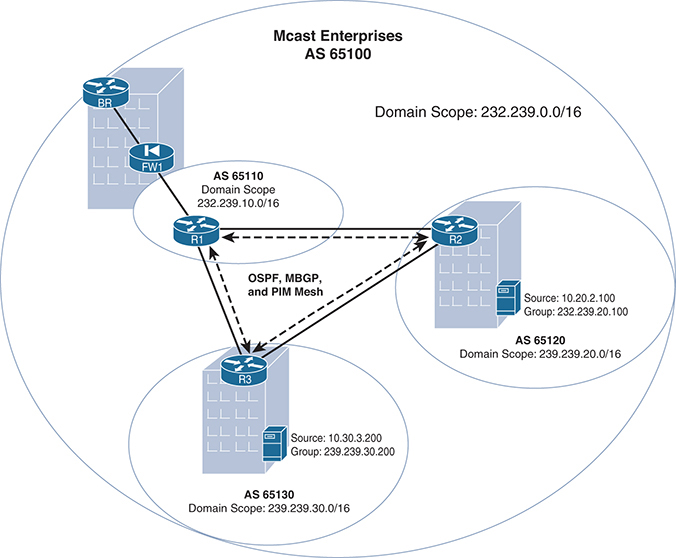
Figure 1-27 Mcast Enterprises Final Design, Using SSM
Note: The IP Multicast group address has been updated to reflect private SSM addresses per RFC 5771.
Wait a minute! If SSM is really so much easier to implement for interdomain multicast, why isn’t the entire Internet using it instead of PIM–SM? This is a good question. There are three answers. First, as a feature, SSM is a relatively recent addition to many networks; it is specified in RFC 4607, published in 2006. Legacy infrastructure support is an important element in any network, including the Internet. Changing the standards is a time-consuming and sometimes expensive process.
The second reason SSM is not the Internet standard for interdomain multicast is control. The PIM–SM model gives autonomous systems far more control over the flow of multicast between domains. While you can still have good interdomain security with SSM, there are far fewer control points. It would be much more difficult to isolate internal domain traffic from external traffic, and mistaken configurations could have far-reaching consequences. The PIM–SM model with MSDP follows the same command and control principles as BGP for this very reason. In fact, achieving similar segmentation with SSM would likely require that many companies use very specific host IPs advertised exclusively by MBGP and that MBGP filtering become the primary method of multicast resource protection—which it was not necessarily designed to do. Thus, an improperly configured SSM domain could cause far-reaching havoc, maybe even globally.
That being said, at the time of this writing at least, SSM interdomain multicast is perfectly suited to intra-AS interdomain multicast. An understanding of basic traffic filtering and basic SSM operations is all that is needed to get started. For more information on SSM operations, refer to IP Multicast, Volume 1.
The third and most relevant reason is that ISP support for multicast is simply not ubiquitous. While it is possible to get multicast across the global Internet, as described in the latter half of this chapter, it is certainly not pervasive as of this writing. It may very well be that in the future, with additional improvements to SSM forwarding, you will see pervasive Internet multicast. However, for the time being, the complexities and lack of uniform support for PIM–SM standards make Internet-based multicast a less attractive service than unicast replication.
IPv6 with Embedded RP
Using IPv6 for interdomain multicast is very simple. For the most part, the configuration of the networks previously shown is identical, only using IPv6 addressing and IPv6 address families to complete the configurations. IPv6-based intra-AS interdomain multicast does have a big advantage over its IPv4 counterpart. IPv6 can simplify the deployment of RPs and eliminate the need for MSDP by using embedded RP.
The embedded RP function of IPv6 allows the address of the RP to be embedded in an IPv6 multicast message. When a downstream router or routers see the group address, the RP information is extracted, and a shared tree is immediately built. In this way, a single centrally controlled RP can provide RP services for multiple domains. This solution works for both interdomain and intra-domain multicast.
The format of the embedded RP address is shown in Figure 1-28 and includes the following:

Figure 1-28 IPv6 with Embedded RP Addressing
![]() 11111111: All group addresses must begin with this bit pattern.
11111111: All group addresses must begin with this bit pattern.
![]() Flags: The 4 bits are defined as 0, R, P, and T, where the most significant bit is 0, R when set to 1 indicates an embedded RP address, and P and T must both equal 1. (For additional information, please refer to RFC 3306/7371.)
Flags: The 4 bits are defined as 0, R, P, and T, where the most significant bit is 0, R when set to 1 indicates an embedded RP address, and P and T must both equal 1. (For additional information, please refer to RFC 3306/7371.)
![]() Scope:
Scope:
![]() 0000–0: Reserved
0000–0: Reserved
![]() 0001–1: Node-local scope
0001–1: Node-local scope
![]() 0010–2: Link-local scope
0010–2: Link-local scope
![]() 0011–3: Unassigned
0011–3: Unassigned
![]() 0100–4: Unassigned
0100–4: Unassigned
![]() 0101–5: Site-local scope
0101–5: Site-local scope
![]() 0110–6: Unassigned
0110–6: Unassigned
![]() 0111–7: Unassigned
0111–7: Unassigned
![]() 1000–8: Organization-local scope
1000–8: Organization-local scope
![]() 1001–9: Unassigned
1001–9: Unassigned
![]() 1010–A: Unassigned
1010–A: Unassigned
![]() 1011–B: Unassigned
1011–B: Unassigned
![]() 1100–C: Unassigned
1100–C: Unassigned
![]() 1101–D: Unassigned
1101–D: Unassigned
![]() 1110–E: Global scope
1110–E: Global scope
![]() 1111–F: Reserved
1111–F: Reserved
![]() RIID (RP Interface ID): Anything except 0.
RIID (RP Interface ID): Anything except 0.
![]() Plen (prefix length): Indicates the number of bits in the network prefix field and must not be equal to 0 or greater than 64.
Plen (prefix length): Indicates the number of bits in the network prefix field and must not be equal to 0 or greater than 64.
To embed the RP address in the message, the prefix must begin with FF70::/12, as shown in Figure 1-29.

Figure 1-29 Embedded RP Address Prefix
You need to copy the number of bits from the network prefix as defined by the value of plen. Finally, the RIID value is appended to the last four least significant bits, as shown in Figure 1-30.

Figure 1-30 Determining the Embedded RP Address
Figure 1-31 provides an example of embedding an RP address.

Figure 1-31 Embedded RP Configuration Example Network
Example 1-31 provides the configurations for the routers shown in Figure 1-31.
Example 1-31 Configurations for IPv6 Embedded RP
hostname R1
ipv6 unicast-routing
ipv6 multicast-routing
!
interface Loopback0
 ip address 192.168.0.1 255.255.255.255
ipv6 address 2001:192::1/128
 ipv6 enable
 ipv6 ospf 65000 area 0
!
interface Ethernet0/0
 no ip address
 ipv6 address 2001:192:168:21::1/64
 ipv6 enable
 ipv6 ospf 65000 area 0
!
interface Ethernet0/1
 no ip address
 ipv6 address 2001:192:168:31::1/64
 ipv6 enable
 ipv6 ospf 65000 area 0
!
interface Ethernet0/2
 no ip address
 load-interval 30
 ipv6 address 2001:192:168:41::1/64
 ipv6 enable
 ipv6 ospf 65000 area 0
!
ipv6 pim rp-address 2001:192::1

!
ipv6 router ospf 65000
 router-id 192.168.0.1


hostname R2
ipv6 unicast-routing
ipv6 multicast-routing
!
interface Loopback0
ip address 192.168.0.2 255.255.255.255
 ipv6 address 2001:192:168::2/128
 ipv6 enable
 ipv6 ospf 65000 area 0
!
interface Ethernet0/0
 no ip address
 ipv6 address 2001:192:168:21::2/64
 ipv6 enable
 ipv6 ospf 65000 area 0
!
interface Ethernet0/1
 no ip address
 ipv6 address 2001:192:168:32::2/64
 ipv6 enable
 ipv6 ospf 65000 area 0
!
interface Ethernet0/2
 no ip address
 ipv6 address 2001:192:168:52::2/64
 ipv6 enable
 ipv6 ospf 65000 area 0
!
ipv6 router ospf 65000
 router-id 192.168.0.2


hostname R3
ipv6 unicast-routing
ipv6 multicast-routing
!
interface Loopback0
 ip address 192.168.0.3 255.255.255.255
 ipv6 address 2001:192:168::3/128
 ipv6 enable
 ipv6 ospf 65000 area 0
!
interface Ethernet0/0
 no ip address
 load-interval 30
 ipv6 address 2001:192:168:31::3/64
 ipv6 enable
 ipv6 ospf 65000 area 0
!
interface Ethernet0/1
 no ip address
 ipv6 address 2001:192:168:32::3/64
 ipv6 enable
 ipv6 ospf 65000 area 0
!
interface Ethernet0/2
 no ip address
 ipv6 address 2001:192:168:63::3/64
 ipv6 enable
 ipv6 mld join-group FF73:105:2001:192::1
 ipv6 ospf 65000 area 0
!
ipv6 router ospf 65000
 router-id 192.168.0.3
As you can see from the configurations in Example 1-31, there isn’t anything too fancy. The highlighted commands on R1 defines R1 as the RP using the loopback 0 interface, with the ipv6 pim rp-address 2001:192::1 command, and the second is on R3, which statically defines a join group by using the ipv6 mld join-group FF73:105:2001:192::1 command.
Note: The ipv6 mld join-group command should be used only temporarily, for troubleshooting purposes only.
You may have noticed that the only router with an RP mapping is R1. Because you are embedding the RP information in the multicast message, it is not necessary to define an RP on every router.
From R2, you can watch the behavior in action by using a simple ping command. As shown in Example 1-32, you can ping the FF73:105:2001:192::1 address configured as a join group on R3.
Example 1-32 Embedded RP Example
R2# ping FF73:105:2001:192::1
Output Interface: ethernet0/1
Type escape sequence to abort.
Sending 5, 100-byte ICMP Echos to FF73:105:2001:192::1, timeout is 2 seconds:
Packet sent with a source address of 2001:192:168:32::2

Reply to request 0 received from 2001:192:168:63::3, 8 ms
Reply to request 1 received from 2001:192:168:63::3, 1 ms
Reply to request 2 received from 2001:192:168:63::3, 1 ms
Reply to request 3 received from 2001:192:168:63::3, 1 ms
Reply to request 4 received from 2001:192:168:63::3, 1 ms
Success rate is 100 percent (5/5), round-trip min/avg/max = 1/2/8 ms
5 multicast replies and 0 errors.
You can see that all the ping packets received replies from R3 (2001:192:168:63::3).
On R3, you can verify the existence of both the (*, G) and (S, G) entries with the command shown in Example 1-33.
Example 1-33 Verifying the PIM Entry with RP Mapping
R3# show ipv6 mroute FF73:105:2001:192::1
Multicast Routing Table
Flags: D - Dense, S - Sparse, B - Bidir Group, s - SSM Group,
       C - Connected, L - Local, I - Received Source Specific Host Report,
       P - Pruned, R - RP-bit set, F - Register flag, T - SPT-bit set,
       J - Join SPT, Y - Joined MDT-data group,
       y - Sending to MDT-data group
       g - BGP signal originated, G - BGP Signal received,
       N - BGP Shared-Tree Prune received, n - BGP C-Mroute suppressed,
       q - BGP Src-Active originated, Q - BGP Src-Active received
       E - Extranet
Timers: Uptime/Expires
Interface state: Interface, State

(*, FF73:105:2001:192::1), 00:13:34/00:02:55, RP 2000::1, flags: SCL
  Incoming interface: Null
  RPF nbr: ::
  Immediate Outgoing interface list:
    Ethernet0/2, Forward, 00:13:34/00:02:55

(2001:192:168:32::2, FF73:105:2001:192::1), 00:03:02/00:00:27, flags: SFT
  Incoming interface: Ethernet0/1
  RPF nbr: FE80::A8BB:CCFF:FE00:210, Registering
  Immediate Outgoing interface list:
    Tunnel0, Forward, 00:03:02/never
    Ethernet0/2, Forward, 00:03:02/00:02:35
Notice that multicast messages are received from interface Ethernet0/1 and sent to the destination interface, Ethernet0/2.
Even though this example is an intra-domain configuration, using IPv6 with embedded RP is a great solution for intra-AS interdomain multicasting. A single RP can be used for all domains, with the mapping function being performed by embedded RP. No additional protocols or interdomain configuration are required as the embedded RP for each group mapping propagates throughout the IPV6 network. However, this is not a very good solution for inter-AS interdomain multicast. The largest difficulty of such a design is the use of a single RP to service multiple ASs. For additional details, refer to RFC 3956.
Summary
This chapter reviews the fundamental requirements for interdomain forwarding of IP multicast flows. An understanding of PIM domains and how they are built on the three pillars of interdomain design is critical for architecting this type of forwarding. Remember that these are the three pillars:
![]() The multicast control plane for source identification: The router must know a proper path to any multicast source, either from the unicast RIB or learned (either statically or dynamically) through a specific RPF exception.
The multicast control plane for source identification: The router must know a proper path to any multicast source, either from the unicast RIB or learned (either statically or dynamically) through a specific RPF exception.
![]() The multicast control plane for receiver identification: The router must know about any legitimate receivers that have joined the group and where they are located in the network.
The multicast control plane for receiver identification: The router must know about any legitimate receivers that have joined the group and where they are located in the network.
![]() The downstream multicast control plane and MRIB: The router must know when a source is actively sending packets for a given group. PIM–SM domains must also be able to build a shared tree from the local domain’s RP, even when the source has registered to a remote RP in a different domain.
The downstream multicast control plane and MRIB: The router must know when a source is actively sending packets for a given group. PIM–SM domains must also be able to build a shared tree from the local domain’s RP, even when the source has registered to a remote RP in a different domain.
Multicast BGP, PIM, and MSDP satisfy the requirements of the three pillars. With these protocols, you should be able to configure any multidomain or interdomain network, including designs that are both internal and cross the public Internet. This chapter also reviews ways to eliminate the use of MSDP by using SSM or IPv6 embedded RP within the network.