
Chapter 6
Advanced Multicast Troubleshooting
IP Multicast, Volume 1 introduces a basic methodology for troubleshooting IP multicast networks. This methodology concentrates on implementations of Any-Source Multicast (ASM) using PIM Sparse-Mode (PIM-SM). To review quickly, there are three ordered steps in this methodology:
1. Receiver check
2. Source check
3. State verification
These fundamental steps of troubleshooting never change, even in advanced multicast designs. As discussed in this book, there are many new protocols and nuances involved in advanced designs. Cross-domain forwarding of multicast over the Internet is a great example. Interdomain multicast introduces Multicast Source Discovery Protocol (MSDP) and Border Gateway Protocol (BGP) into the multicast design. In addition, source, receiver, and state checks can be complicated if there are multiple domains, some of which are under the control of entities other than your own.
Despite these additional protocols and elements, with troubleshooting, you always start at the beginning. The following is a breakdown of this three-element methodology into high-level steps for troubleshooting multicast in a single domain:
Note: Certain protocol and router checks have been added to each of these steps to help identify where the source of the problem exists. These high-level steps are found in IP Multicast, Volume 1 Chapter 7, “Operating and Troubleshooting IP Multicast Networks.”
Step 1. Receiver check. Make sure a receiver is subscribed via Internet Group Management Protocol (IGMP) and that a (*, G) to the rendezvous point (RP) exists (if using PIM-SM):
![]() Check the group state on the last-hop router (LHR).
Check the group state on the last-hop router (LHR).
![]() Check IGMP membership on the last-hop PIM-designated router (DR).
Check IGMP membership on the last-hop PIM-designated router (DR).
![]() Verify the (*, G) state at the LHR and check the RP for the (*, G) entry and Reverse Path Forwarding (RPF).
Verify the (*, G) state at the LHR and check the RP for the (*, G) entry and Reverse Path Forwarding (RPF).
Step 2. Source check. Make sure you have an active source before trying to troubleshoot:
![]() Verify that the source is sending the multicast traffic to the first-hop router (FHR).
Verify that the source is sending the multicast traffic to the first-hop router (FHR).
![]() Confirm that the FHR has registered the group with the RP.
Confirm that the FHR has registered the group with the RP.
![]() Determine that the RP is receiving the register messages.
Determine that the RP is receiving the register messages.
![]() Confirm that the multicast state is built on the FHR.
Confirm that the multicast state is built on the FHR.
Step 3. State verification. Ensure that each router in the path has correct RPF information by using the show ip rpf <IP_address> command:
![]() Verify the RP and shortest-path tree (SPT) state entries across the path:
Verify the RP and shortest-path tree (SPT) state entries across the path:
![]() Check the MSDP summary to verify that peering is operational.
Check the MSDP summary to verify that peering is operational.
![]() Verify the group state at each active RP.
Verify the group state at each active RP.
![]() Verify SPT changes.
Verify SPT changes.
![]() Verify the mroute state information for the following elements:
Verify the mroute state information for the following elements:
![]() Verify that the incoming interface list (IIF) is correct.
Verify that the incoming interface list (IIF) is correct.
![]() Verify that the outgoing interface list (OIF) is correct.
Verify that the outgoing interface list (OIF) is correct.
![]() Ensure that the flags for (*, G) and (S, G) entries are correct and that the RP information is correct.
Ensure that the flags for (*, G) and (S, G) entries are correct and that the RP information is correct.
![]() Does this align with the information in the mroute entry?
Does this align with the information in the mroute entry?
![]() Is this what you would expect when looking at the unicast routing table?
Is this what you would expect when looking at the unicast routing table?
It is helpful to examine the troubleshooting steps for some of the different types of advanced designs introduced in this book. As shown here, you need to adjust the steps to include additional checks for the protocols in use with each technology. However, the basic three-step process is always used. This chapter covers these concepts and expands on your knowledge of advanced multicasting protocols, starting with interdomain multicast forwarding.
Troubleshooting Interdomain Multicast Networks
To find and repair trouble in an interdomain network, you can follow the basic three-step methodology and high-level steps with some additional checks to accommodate for interdomain PIM neighborships, proper MSDP source-active (SA) handling, and Multiprotocol BGP (MBGP) state sharing (if present). Remember, first and foremost, you must have at least one active receiver and one active source for a given group, regardless of which domains they are in. Write out the same high-level steps previously mentioned and add these elements:
Step 1. Receiver check. Make sure a receiver is subscribed via IGMP and that a (*, G) to the RP exists before trying to troubleshoot:
![]() Check the group state on the LHR.
Check the group state on the LHR.
![]() Check IGMP membership on the last-hop PIM DR.
Check IGMP membership on the last-hop PIM DR.
![]() Verify the (*, G) state at the LHR and check the RP for the (*, G) entry and RPF.
Verify the (*, G) state at the LHR and check the RP for the (*, G) entry and RPF.
Step 2. Source check. Make sure you have an active source before trying to troubleshoot (the source will be in a different domain from the receiver):
![]() Verify that the source is sending the multicast traffic to the FHR.
Verify that the source is sending the multicast traffic to the FHR.
![]() Confirm that the FHR has registered the group with the RP.
Confirm that the FHR has registered the group with the RP.
![]() Determine whether the source domain RP is receiving the registry messages.
Determine whether the source domain RP is receiving the registry messages.
![]() Confirm that the multicast state is built on the FHR.
Confirm that the multicast state is built on the FHR.
![]() Ensure that the RP is running MSDP and is adding the source to the MSDP SA cache.
Ensure that the RP is running MSDP and is adding the source to the MSDP SA cache.
![]() Confirm that the source domain RP is advertising this route to its MSDP neighbor RPs.
Confirm that the source domain RP is advertising this route to its MSDP neighbor RPs.
Step 3. State verification. Ensure that each router in the path has correct RPF information by using the show ip rpf <IP_address> command:
![]() Verify RP and SPT state entries across the path at each RP router, starting with the LHR:
Verify RP and SPT state entries across the path at each RP router, starting with the LHR:
![]() Ensure that each router interface in the path has appropriate PIM neighborships.
Ensure that each router interface in the path has appropriate PIM neighborships.
![]() Discover whether the RP local to the LHR is running MSDP and whether it has either an (S, G) entry or an entry in the MSDP SA cache for the (S, G).
Discover whether the RP local to the LHR is running MSDP and whether it has either an (S, G) entry or an entry in the MSDP SA cache for the (S, G).
![]() Check the MSDP peerings on each RP for every domain in the path to verify that peering is operational end-to-end.
Check the MSDP peerings on each RP for every domain in the path to verify that peering is operational end-to-end.
![]() Verify the group state at each active RP.
Verify the group state at each active RP.
![]() Verify SPT changes at each RP.
Verify SPT changes at each RP.
![]() If MBGP is in use, verify the following:
If MBGP is in use, verify the following:
![]() Is each MSDP-enabled RP also an MBGP peer, to prevent black-holing?
Is each MSDP-enabled RP also an MBGP peer, to prevent black-holing?
![]() Is the MSDP-enabled RP running BGP receiving an NLRI entry that covers the source IP?
Is the MSDP-enabled RP running BGP receiving an NLRI entry that covers the source IP?
![]() Is the next-hop router in the NLRI entry a PIM neighbor of the local domain?
Is the next-hop router in the NLRI entry a PIM neighbor of the local domain?
![]() Verify the mroute state information for the following elements at every router in the path:
Verify the mroute state information for the following elements at every router in the path:
![]() Verify that the IIF is correct.
Verify that the IIF is correct.
![]() Verify that the OIF is correct.
Verify that the OIF is correct.
![]() Ensure that the flags for (*, G) and (S, G) entries are correct and that the RP information is correct.
Ensure that the flags for (*, G) and (S, G) entries are correct and that the RP information is correct.
![]() Does this align with the information in the mroute entry?
Does this align with the information in the mroute entry?
![]() Is this what you would expect when looking at the unicast routing table?
Is this what you would expect when looking at the unicast routing table?
Let’s put the methodology to work, using the example of the final ASM multidomain network from Chapter 1, “Interdomain Routing and Internet Multicast,” with a couple problems introduced into the configuration so that you can use the methodology to sniff them out and repair them. Figure 6-1 depicts the high-level ASM network as completed in Chapter 1, and Figure 6-2 shows the interface map for the routers in the path between the source and the client.
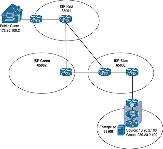
Figure 6-1 Final Interdomain IP Multicast Design from Chapter 1
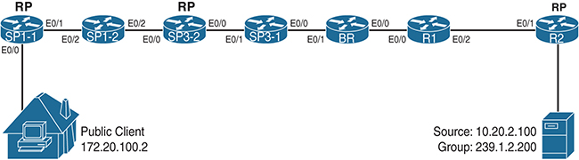
Figure 6-2 Interdomain IP Multicast Design Interface Map
Remember that in this design, Enterprise Company is offering up content to clients on the public Internet via group 239.1.2.200. Enterprise Company routers are configured as a single domain, and the BR router has an MSDP and MBGP relationship with router SP3-1 in Internet service provider (ISP) Blue. The ISPs have interconnected multicast domains. At the end of this configuration example, the client at public IP 172.21.100.2 was able to receive multicast packets from the source at 10.20.2.200 (see Example 6-1).
Example 6-1 Multicast Reachability from Source to Client for 10.20.2.100, 239.1.2.200
Server2# ping 239.1.2.200
Type escape sequence to abort.
Sending 1, 100-byte ICMP Echos to 239.1.2.200, timeout is 2 seconds:

Reply to request 0 from 172.21.100.2, 4 ms
Sometime after the completion of this configuration, the client stops receiving multicast. As shown in Example 6-2, a simple ping test indicates that the client is no longer responding to multicast pings.
Example 6-2 Multicast Reachability Broken from Source to Client for 10.20.2.200
Server2# ping 239.1.2.200
Type escape sequence to abort.
Sending 1, 100-byte ICMP Echos to 239.1.2.200, timeout is 2 seconds:
. . .
To figure out what the problem is, you can start with step 1 at the LHR to discover what happened:
Step 1. Receiver check. Make sure a receiver is subscribed via IGMP and that (*, G) to the RP exists before trying to troubleshoot:
![]() Check the group state on the LHR.
Check the group state on the LHR.
![]() Check IGMP membership on the last-hop PIM DR.
Check IGMP membership on the last-hop PIM DR.
![]() Verify the (*, G) state at the LHR and check the RP for the (*, G) entry and RPF.
Verify the (*, G) state at the LHR and check the RP for the (*, G) entry and RPF.
Use the commands show ip igmp groups, show ip pim rp mapping, and show ip mroute 239.1.2.200 on the LHR, SP1-1, to confirm proper receiver joins and proper RP mapping. Example 6-3 shows the output for these commands, issued on SP1-1.
Example 6-3 Receiver Checking Output on SP1-1
SP1-1# show ip igmp groups
IGMP Connected Group Membership
Group Address    Interface                Uptime    Expires   Last Reporter   Group
Accounted
239.1.2.200      Ethernet0/0              6d00h     00:02:27  172.21.100.2
224.0.1.40       Ethernet0/0              6d00h     00:02:22  172.21.100.1

SP1-1# show ip pim rp mapping
PIM Group-to-RP Mappings

Group(s): 224.0.0.0/4, Static
    RP: 172.21.0.2 (?)

SP1-1# show ip mroute 239.1.2.200
IP Multicast Routing Table
Flags: D - Dense, S - Sparse, B - Bidir Group, s - SSM Group, C - Connected,
       L - Local, P - Pruned, R - RP-bit set, F - Register flag,
       T - SPT-bit set, J - Join SPT, M - MSDP created entry, E - Extranet,
       X - Proxy Join Timer Running, A - Candidate for MSDP Advertisement,
       U - URD, I - Received Source Specific Host Report,
       Z - Multicast Tunnel, z - MDT-data group sender,
       Y - Joined MDT-data group, y - Sending to MDT-data group,
       G - Received BGP C-Mroute, g - Sent BGP C-Mroute,
       N - Received BGP Shared-Tree Prune, n - BGP C-Mroute suppressed,
       Q - Received BGP S-A Route, q - Sent BGP S-A Route,
       V - RD & Vector, v - Vector, p - PIM Joins on route
Outgoing interface flags: H - Hardware switched, A - Assert winner, p - PIM Join
 Timers: Uptime/Expires
 Interface state: Interface, Next-Hop or VCD, State/Mode
(*, 239.1.2.200), 6d00h/00:02:23, RP 172.21.0.2, flags: SJC
  Incoming interface: Ethernet0/1, RPF nbr 172.21.1.2
  Outgoing interface list:
    Ethernet0/0, Forward/Sparse, 6d00h/00:02:23
As you can see in Example 6-3, the receiver is joined via IGMP to the group, and a (*, G) for the group exists in the mroute table. Next, check the RP in the receiver’s domain for the proper (*, G) state—in this case (*, 239.1.2.200). The RP router for the receiver’s domain, ISP Red, is SP1-2. show ip mroute 239.1.2.200 confirms that the entry is correct, as shown in Example 6-4.
Example 6-4 Checking the RP for (*, G)
SP1-2# show ip mroute 239.1.2.200
IP Multicast Routing Table
Flags: D - Dense, S - Sparse, B - Bidir Group, s - SSM Group, C - Connected,
       L - Local, P - Pruned, R - RP-bit set, F - Register flag,
       T - SPT-bit set, J - Join SPT, M - MSDP created entry, E - Extranet,
       X - Proxy Join Timer Running, A - Candidate for MSDP Advertisement,
       U - URD, I - Received Source Specific Host Report,
       Z - Multicast Tunnel, z - MDT-data group sender,
       Y - Joined MDT-data group, y - Sending to MDT-data group,
       G - Received BGP C-Mroute, g - Sent BGP C-Mroute,
       N - Received BGP Shared-Tree Prune, n - BGP C-Mroute suppressed,
       Q - Received BGP S-A Route, q - Sent BGP S-A Route,
       V - RD & Vector, v - Vector, p - PIM Joins on route
Outgoing interface flags: H - Hardware switched, A - Assert winner, p - PIM Join
 Timers: Uptime/Expires

Interface state: Interface, Next-Hop or VCD, State/Mode
(*, 239.1.2.200), 6d01h/00:02:46, RP 172.21.0.2, flags: S
  Incoming interface: Null, RPF nbr 0.0.0.0
  Outgoing interface list:
    Ethernet0/2, Forward/Sparse, 6d01h/00:02:46
Notice that the RP, SP1-2, has the correct entry. Assume that the receiver checks out. However, also note from this entry that the IIF is Null and has no RPF neighbor. You can move to step 2 of the troubleshooting methodology to check the source:
Step 2. Source check. Make sure you have an active source before trying to troubleshoot (the source is in a different domain from the receiver):
![]() Verify that the source is sending the multicast traffic to the FHR.
Verify that the source is sending the multicast traffic to the FHR.
![]() Confirm that the FHR registered the group with the RP.
Confirm that the FHR registered the group with the RP.
![]() Determine whether the source domain RP is receiving the registry messages.
Determine whether the source domain RP is receiving the registry messages.
![]() Confirm that the multicast state is built on the FHR.
Confirm that the multicast state is built on the FHR.
![]() Ensure that the RP is running MSDP and is adding the source to the MSDP SA cache.
Ensure that the RP is running MSDP and is adding the source to the MSDP SA cache.
![]() Confirm that the source domain RP is advertising this route to its MSDP neighbor RPs.
Confirm that the source domain RP is advertising this route to its MSDP neighbor RPs.
In this case, the source is in Enterprise Company’s domain. The FHR for the source, 10.20.2.200, is R2. This is where you start. You first check that the source is indeed sending a multicast stream and verify that R2 has the appropriate (S, G) state information for the source and group. You can check both of these items with the simple commands show ip mroute 239.1.2.200 and show ip pim rp mapping. In addition, because R2 is also the RP, you should check for MSDP SA cache entries and peers by using the commands show ip msdp sa-cache and show ip msdp summary. Example 6-5 shows the outputs for these commands.
Example 6-5 Checking for Source State and RP Registration on the FHR
R2# show ip mroute 239.1.2.200
IP Multicast Routing Table
Flags: D - Dense, S - Sparse, B - Bidir Group, s - SSM Group, C - Connected,
       L - Local, P - Pruned, R - RP-bit set, F - Register flag,
       T - SPT-bit set, J - Join SPT, M - MSDP created entry, E - Extranet,
       X - Proxy Join Timer Running, A - Candidate for MSDP Advertisement,
       U - URD, I - Received Source Specific Host Report,
       Z - Multicast Tunnel, z - MDT-data group sender,
       Y - Joined MDT-data group, y - Sending to MDT-data group,
       G - Received BGP C-Mroute, g - Sent BGP C-Mroute,
       N - Received BGP Shared-Tree Prune, n - BGP C-Mroute suppressed,
       Q - Received BGP S-A Route, q - Sent BGP S-A Route,
       V - RD & Vector, v - Vector, p - PIM Joins on route
Outgoing interface flags: H - Hardware switched, A - Assert winner, p - PIM Join
 Timers: Uptime/Expires
 Interface state: Interface, Next-Hop or VCD, State/Mode

(*, 239.1.2.200), 00:00:12/stopped, RP 10.0.0.2, flags: SP
  Incoming interface: Null, RPF nbr 0.0.0.0
  Outgoing interface list: Null

(10.20.2.200, 239.1.2.200), 00:00:12/00:02:47, flags: PTA
  Incoming interface: Ethernet0/0, RPF nbr 0.0.0.0
  Outgoing interface list: Null

R2# show ip pim rp mapping
PIM Group-to-RP Mappings

Group(s): 224.0.0.0/4, Static-Override
    RP: 10.0.0.2 (?)
R2# show ip msdp summary
MSDP Peer Status Summary
Peer Address     AS    State    Uptime/  Reset SA    Peer Name
                                Downtime Count Count
10.0.0.1         65101 Up       1w0d     0     0     ?
R2# show ip msdp sa-cache
MSDP Source-Active Cache - 1 entries
(10.20.2.200, 239.1.2.200), RP 10.0.0.2, MBGP/AS 65102, 00:03:04/00:05:10
Note from the highlighted output in Example 6-5 that source 10.20.2.200 is indeed sending packets to the group 239.1.2.200. This router is the RP for this group, and therefore you know that the source is registered. In addition, MSDP has added the (S, G) as an active SA in the cache and should be sending to any peers, in this case 10.0.0.1. However, there is a problem in the state entry for this (S, G). Can you identify it? (Hint: It is in the last line of the highlighted output.)
That’s right, there is no valid OIF, as indicated by Null in the output. This means the router does not know of any downstream receivers for this group. What might be causing this issue? There is a good, properly registered source. You can move to step 3 in the process to check the state and configuration of each router in the path between the FHR and the LHR for this scenario:
Step 3. State verification. Ensure that each router in the path has correct RPF information by using the show ip rpf <IP_address> command:
![]() Verify RP and SPT state entries across the path at each RP router, starting with the LHR:
Verify RP and SPT state entries across the path at each RP router, starting with the LHR:
![]() Ensure that each router interface in the path has appropriate PIM neighborships.
Ensure that each router interface in the path has appropriate PIM neighborships.
![]() Discover whether the RP local to the LHR is running MSDP and whether it has either an (S, G) entry or an entry in the MSDP SA cache for the (S, G).
Discover whether the RP local to the LHR is running MSDP and whether it has either an (S, G) entry or an entry in the MSDP SA cache for the (S, G).
![]() Check the MSDP peerings on each RP for every domain in the path to verify that peering is operational end-to-end.
Check the MSDP peerings on each RP for every domain in the path to verify that peering is operational end-to-end.
![]() Verify the group state at each active RP.
Verify the group state at each active RP.
![]() Verify SPT changes at each RP.
Verify SPT changes at each RP.
![]() If MBGP is in use, verify the following:
If MBGP is in use, verify the following:
![]() Is each MSDP-enabled RP also an MBGP peer, to prevent black-holing?
Is each MSDP-enabled RP also an MBGP peer, to prevent black-holing?
![]() Is the MSDP-enabled RP running BGP receiving an NLRI entry that covers the source IP?
Is the MSDP-enabled RP running BGP receiving an NLRI entry that covers the source IP?
![]() Is the next-hop router in the NLRI entry a PIM neighbor of the local domain?
Is the next-hop router in the NLRI entry a PIM neighbor of the local domain?
![]() Verify the mroute state information for the following elements at every router in the path:
Verify the mroute state information for the following elements at every router in the path:
![]() Verify that the IIF is correct.
Verify that the IIF is correct.
![]() Verify that the OIF is correct.
Verify that the OIF is correct.
![]() Ensure that the flags for (*, G) and (S, G) entries are correct and that the RP information is correct.
Ensure that the flags for (*, G) and (S, G) entries are correct and that the RP information is correct.
![]() Does this align with the information in the mroute entry?
Does this align with the information in the mroute entry?
![]() Is this what you would expect when looking at the unicast routing table?
Is this what you would expect when looking at the unicast routing table?
The first part of step 3 is to ensure that there is a proper PIM neighborship at each interface in the path. Use the show ip pim neighbor command at each router, starting with the FHR and moving toward the LHR, as shown in Example 6-6.
Example 6-6 Checking for PIM Neighborships Along the Path
R2# show ip pim neighbor
PIM Neighbor Table
Mode: B - Bidir Capable, DR - Designated Router, N - Default DR Priority,
      P - Proxy Capable, S - State Refresh Capable, G - GenID Capable
Neighbor          Interface                Uptime/Expires    Ver   DR
Address                                                            Prio/Mode
10.1.2.1          Ethernet0/1              2w4d/00:01:37     v2    1 / S P G

BR# show ip pim neighbor
PIM Neighbor Table
Mode: B - Bidir Capable, DR - Designated Router, N - Default DR Priority,
      P - Proxy Capable, S - State Refresh Capable, G - GenID Capable
Neighbor          Interface                Uptime/Expires    Ver   DR
Address                                                            Prio/Mode
10.1.4.1          Ethernet0/0              1w0d/00:01:43     v2    1 / S P G
You don’t have to go very far before you find the first problem. The BR router for Enterprise Company should definitely have more than one neighbor. In this case, remember, the BR is connected to router R1 on E0/0. Where is the PIM connection for the ISP Blue router SP3-1? You can check the interface configurations on each side to see if there is an error in the configuration that might cause this problem. In this case, interface E0/1 on the BR connects to interface E0/0 on router SP3-1. The command show running-config interface EX/X gives you the output needed to analyze the PIM configuration for each router, as shown in Example 6-7.
Example 6-7 Checking the PIM Configurations of Each Relevant Interface
BR# show running-config interface e0/1
Building configuration...

Current configuration : 142 bytes
!
interface Ethernet0/1
 description Connection_to_E0/0_SP3-1
 ip address 172.23.31.4 255.255.255.0
 ip access-group 101 in
 ip access-group MCAST_OUT out
 ip pim sparse-mode
SP3-1# show running-config interface e0/0
Building configuration...
Current configuration : 67 bytes
!
interface Ethernet0/0
 ip address 172.23.31.1 255.255.255.0
Well, there is a major problem in the network right there: Someone mistakenly removed the PIM configuration on E0/0 on SP3-1! You can quickly fix this issue and see what happens to the mroute entry on R2. Example 6-8 shows the configuration fix for SP3-1 and the show ip mroute 239.1.2.200 command issued again on R2. Notice the PIM DR Up console message on SP3-1 that appears immediately after configuration. This will correspond to the highlighted text request in the example.
Example 6-8 Restoring the PIM Configuration on Router SP3-1
SP3-1(config-if)# ip pim sparse-mode
SP3-1(config-if)#
*Mar 16 23:45:50.205: %PIM-5-NBRCHG: neighbor 172.23.31.4 UP on interface
 Ethernet0/0
*Mar 16 23:45:50.246: %PIM-5-DRCHG: DR change from neighbor 0.0.0.0 to 172.23.31.4
 on interface Ethernet0/0

R2# sh ip mroute 239.1.2.200
IP Multicast Routing Table
Flags: D - Dense, S - Sparse, B - Bidir Group, s - SSM Group, C - Connected,
       L - Local, P - Pruned, R - RP-bit set, F - Register flag,
       T - SPT-bit set, J - Join SPT, M - MSDP created entry, E - Extranet,
       X - Proxy Join Timer Running, A - Candidate for MSDP Advertisement,
       U - URD, I - Received Source Specific Host Report,
       Z - Multicast Tunnel, z - MDT-data group sender,
       Y - Joined MDT-data group, y - Sending to MDT-data group,
       G - Received BGP C-Mroute, g - Sent BGP C-Mroute,
       N - Received BGP Shared-Tree Prune, n - BGP C-Mroute suppressed,
       Q - Received BGP S-A Route, q - Sent BGP S-A Route,
       V - RD & Vector, v - Vector, p - PIM Joins on route
Outgoing interface flags: H - Hardware switched, A - Assert winner, p - PIM Join
 Timers: Uptime/Expires
 Interface state: Interface, Next-Hop or VCD, State/Mode


(*, 239.1.2.200), 00:36:41/stopped, RP 10.0.0.2, flags: SP
  Incoming interface: Null, RPF nbr 0.0.0.0
  Outgoing interface list: Null

(10.20.2.200, 239.1.2.200), 00:36:41/00:02:57, flags: PTA
  Incoming interface: Ethernet0/0, RPF nbr 0.0.0.0
  Outgoing interface list: Null
It appears that there is still a problem at the FHR. The OIF still shows Null. You are going to have to keep working through step 3 to hunt down any remaining problems. Step 3 suggests that you check the RP for the LHR to determine if it is running MSDP and if it has an entry in the SA cache for the source/group pair (10.20.2.200, 239.1.2.200). The RP for ISP Red is router SP1-2. Use the show ip msdp sa-cache command to check for the entry in question (see Example 6-9).
Example 6-9 Checking the LHR RP MSDP SA State
SP1-2# show ip msdp sa-cache
MSDP Source-Active Cache - 0 entries
That’s not correct; the MSDP SA cache on the RP is empty! You need to walk the path back to the FHR MSDP speaker to find if there is a problem with MSDP. You can run show ip msdp summary on SP1-2 and then again on each of the RPs in the path. If you combine this with the command show ip msdp sa-cache at each of those hops, you may find exactly where the breakdown in MSDP has occurred. Example 6-10 provides the appropriate output.
Note: For this exercise, you already know that the RP/MSDP peer in the path at ISP Blue is SP3-2 and R1 at Enterprise Company. However, this output helps visualize this peering, along with the SA cache entries at each hop.
Example 6-10 MSDP Peering and SA Check, Hop by Hop
FOR ISP RED:

SP1-2# show ip msdp summary
MSDP Peer Status Summary
Peer Address     AS    State    Uptime/  Reset SA    Peer Name
                                Downtime Count Count
172.22.0.1       65002 Up       1w0d     0     0     ?
172.23.0.2       65003 Up       1w0d     0     0     ?


FOR ISP BLUE:
SP3-2# show ip msdp summary
MSDP Peer Status Summary
Peer Address     AS    State    Uptime/  Reset SA    Peer Name
                                Downtime Count Count
10.0.0.1         65100 Up       00:06:10 2     0     ?
172.22.0.1       65002 Up       1w0d     0     0     ?
172.21.0.2       65001 Up       1w0d     0     0     ?


SP3-2# show ip msdp sa-cache
MSDP Source-Active Cache - 0 entries


FOR ENTERPRISE:
R1# show ip msdp summary
MSDP Peer Status Summary
Peer Address     AS    State    Uptime/  Reset SA    Peer Name
                                Downtime Count Count
172.23.0.2       65003 Up       1w0d     0     0     ?
10.0.0.2         65102 Up       1w0d     0     1     ?
10.0.0.3         65103 Up       1w0d     0     0     ?

R1# show ip msdp sa-cache
MSDP Source-Active Cache - 1 entries
(10.20.2.200, 239.1.2.200), RP 10.0.0.2, MBGP/AS 65101, 01:00:49/00:05:14,
  Peer 10.0.0.2
Notice that SP1-2, SP3-2, and R1 all have the correct MSDP peerings, as highlighted. However, R1 has the appropriate SA cache entry for the (S, G), but SP3-2 does not. You have identified a second problem: The SA entry is not getting installed in each RP in the path!
You need to correct this problem before moving on to the next parts of step 3. Make sure the end-to-end PIM path builds an RPF checked source tree at each domain in the overall network. Without this, you will always have an incomplete source tree at the downstream domains. To discover the trouble, use the debug ip msdp detail command at R1 and SP3-2, where the peering and SA cache entries seem to break down. Example 6-11 gives the debug output for a few minutes on each router.
Example 6-11 Debugging MSDP to Identify the Problem
R1# debug ip msdp detail
MSDP Detail debugging is on
<..>
*Mar 16 23:59:07.535: MSDP(0): Received 3-byte TCP segment from 172.23.0.2
*Mar 17 00:01:28.877: MSDP(0): start_index = 0, sa_cache_index = 0, Qlen = 0
*Mar 17 00:01:28.877: MSDP(0): Sent entire sa-cache, sa_cache_index = 0, Qlen = 0
*Mar 17 00:01:38.956: MSDP(0): Received 20-byte TCP segment from 10.0.0.2
*Mar 17 00:01:38.956: MSDP(0): Append 20 bytes to 0-byte msg 31149 from 10.0.0.2, qs 1
*Mar 17 00:01:38.956: MSDP(0): (10.20.2.200/32, 239.1.2.200), accepted
*Mar 17 00:01:41.954: MSDP(0): start_index = 0, mroute_cache_index = 0, Qlen = 0
*Mar 17 00:01:41.954: MSDP(0): Sent entire mroute table, mroute_cache_index = 0, Qlen = 0
*Mar 17 00:01:41.954: MSDP(0): start_index = 0, sa_cache_index = 0, Qlen = 0
*Mar 17 00:01:41.954: MSDP(0): Sent entire sa-cache, sa_cache_index = 0, Qlen = 0
*Mar 17 00:02:08.332: MSDP(0): Received 3-byte TCP segment from 172.23.0.2
*Mar 17 00:02:08.332: MSDP(0): Append 3 bytes to 0-byte msg 31150 from 172.23.0.2, qs 1
*Mar 17 00:00:49.345: MSDP(0): Received 3-byte TCP segment from 172.21.0.2
*Mar 17 00:00:49.345: MSDP(0): Append 3 bytes to 0-byte msg 31737 from 172.21.0.2, qs 1
*Mar 17 00:00:50.969: MSDP(0): start_index = 0, mroute_cache_index = 0, Qlen = 0
*Mar 17 00:00:50.969: MSDP(0): Sent entire mroute table, mroute_cache_index = 0, Qlen = 0

SP3-2# debug ip msdp detail
MSDP Detail debugging is on
<..>
*Mar 17 00:01:01.006: MSDP(0): start_index = 0, sa_cache_index = 0, Qlen = 0
*Mar 17 00:01:01.006: MSDP(0): Sent entire sa-cache, sa_cache_index = 0, Qlen = 0
*Mar 17 00:01:24.567: MSDP(0): Received 3-byte TCP segment from 172.22.0.1
*Mar 17 00:01:24.567: MSDP(0): Append 3 bytes to 0-byte msg 31738 from 172.22.0.1, qs 1
*Mar 17 00:01:28.877: MSDP(0): Received 20-byte TCP segment from 10.0.0.1
*Mar 17 00:01:28.877: MSDP(0): Append 20 bytes to 0-byte msg 31739 from 10.0.0.1, qs 1
*Mar 17 00:01:43.207: MSDP(0): start_index = 0, mroute_cache_index = 0, Qlen = 0
*Mar 17 00:01:43.207: MSDP(0): Sent entire mroute table, mroute_cache_index = 0, Qlen = 0
*Mar 17 00:01:43.207: MSDP(0): start_index = 0, sa_cache_index = 0, Qlen = 0
*Mar 17 00:01:43.207: MSDP(0): Sent entire sa-cache, sa_cache_index = 0, Qlen = 0
*Mar 17 00:01:49.652: MSDP(0): Received 3-byte TCP segment from 172.21.0.2
*Mar 17 00:01:49.652: MSDP(0): Append 3 bytes to 0-byte msg 31740 from 172.21.0.2, qs 1
*Mar 17 00:01:54.249: MSDP(0): start_index = 0, mroute_cache_index = 0, Qlen = 0
*Mar 17 00:01:54.249: MSDP(0): Sent entire mroute table, mroute_cache_index = 0, Qlen = 0
<..>
Notice that there are a lot of debug messages for this command, and not all of them are helpful. The important messages to review are highlighted. For example, the highlighted output from R1 clearly shows that it received an MSDP update from R2. It also shows that the update included an SA entry for (10.20.2.200, 239.1.2.200) and that it was accepted. Accepted is a keyword in MSDP speak; it means that the SA entry was received and installed into the SA cache on the RP. It also means that the MSDP process on R1 will repackage the update and forward it to its peers.
However, look at the highlighted debug output from SP3-2. It also clearly shows that R1 has sent a 20-byte update, a clear indicator that an SA message was received. The SA cache, remember, was still empty. There is also no indication that the SA entry was accepted by SP3-2. You need to find out why. The quickest way to discover if the SA entry was received but rejected is by using the show ip msdp sa-cache rejected-sa command. Example 6-12 shows output of this command from router SP3-2.
Example 6-12 Rejected SA Cache Entries
SP3-2# show ip msdp sa-cache rejected-sa
MSDP Rejected SA Cache
1 rejected SAs received over 00:01:44, cache size: 100 entries
Timestamp (source, group)
638628.861, (10.20.2.200, 239.1.2.200), RP: 10.0.0.2
Note: You must first enable caching of rejected entries for this feature to work on operating systems that offer support for rejected SA caching. The command to accomplish this for IOS-XE, the operating system in use for this example, is ip msdp cache-rejected-sa number, where number is the total entries you allow the router to cache.
The MSDP process on RP SP3-2 is rejecting the (10.20.2.200, 239.1.2.200) SA cache entry. If the entry is rejected, it will never be forwarded to the RP/MSDP Peer, SP1-2, in the domain of the LHR. Without that information, neither ISP domain can complete a source tree. You need to check the MSDP configuration on SP3-2 and look for any configuration issues. You can use the show running-config | begin ip msdp command to see only the relevant configuration, as shown in Example 6-13.
Example 6-13 MSDP Configuration Check
SP3-2# show run | begin msdp
ip msdp peer 10.0.0.1 connect-source Loopback0 remote-as 65100
ip msdp sa-filter in 10.0.0.1 route-map MSDP-FILTER
ip msdp peer 172.22.0.1 connect-source Loopback0 remote-as 65002
ip msdp peer 172.21.0.2 connect-source Loopback0 remote-as 65001
ip msdp cache-sa-state
ip msdp cache-rejected-sa 100
ip route 172.23.0.0 255.255.0.0 Null0
!
!
route-map MSDP-FILTER deny 10
!
route-map MSDP-FILTER permit 20
Notice from the highlighted text that there is another configuration problem at SP3-2. It looks like ISP Blue is making multicast life difficult! In this case, an MSDP filter was added. The route map used for the filter, however, is misconfigured as the deny statement at place 10 in the route map has no criteria. This causes a “match-all” scenario to occur and denies all SA entries from being installed.
Remove the filter command from SP3-2 and use the show ip msdp sa-cache command to see if this resolves this problem. Wait a minute to allow the update from R1 to come in and get accepted. You can also simultaneously run the debug ip msdp detail command again to capture when that happens and to look for an “Accept(ed)” for the entry. Example 6-14 shows the relevant output from these commands on SP3-2.
Example 6-14 Repairing the MSDP SA Cache
SP3-2# config t
Enter configuration commands, one per line.  End with CNTL/Z.
SP3-2(config)#no ip msdp sa-filter in 10.0.0.1 route-map MSDP-FILTER
SP3-2(config)#exit

SP3-2# debug ip msdp detail
*Mar 17 00:54:20.197: MSDP(0): Received 20-byte TCP segment from 10.0.0.1
*Mar 17 00:54:20.197: MSDP(0): Append 20 bytes to 0-byte msg 31899 from 10.0.0.1,  qs 1
*Mar 17 00:54:20.197: MSDP(0): (10.20.2.200/32, 239.1.2.200) RP 10.0.0.2 Accepted

SP3-2# show ip msdp sa-cache
MSDP Source-Active Cache - 1 entries
(10.20.2.200, 239.1.2.200), RP 10.0.0.2, BGP/AS 65100, 00:00:17/00:05:46, Peer 10.0.0.1
Learned from peer 10.0.0.1, RPF peer 10.0.0.1,
SAs received: 2, Encapsulated data received: 0
The SA is now installed in the SA cache on the RP. SP3-2 forwards this SA in an update to the LHR domain RP, SP1-2. Now that this problem is resolved, you can continue with step 3. Return to SP1-1, the LHR, and check the state information for the group by using the show ip mroute command once again. Example 6-15 shows the output of this command.
Example 6-15 mroute State on the LHR
SP1-1# show ip mroute 239.1.2.200
IP Multicast Routing Table
Flags: D - Dense, S - Sparse, B - Bidir Group, s - SSM Group, C - Connected,
       L - Local, P - Pruned, R - RP-bit set, F - Register flag,
       T - SPT-bit set, J - Join SPT, M - MSDP created entry, E - Extranet,
       X - Proxy Join Timer Running, A - Candidate for MSDP Advertisement,
       U - URD, I - Received Source Specific Host Report,
       Z - Multicast Tunnel, z - MDT-data group sender,
       Y - Joined MDT-data group, y - Sending to MDT-data group,
       G - Received BGP C-Mroute, g - Sent BGP C-Mroute,
       N - Received BGP Shared-Tree Prune, n - BGP C-Mroute suppressed,
       Q - Received BGP S-A Route, q - Sent BGP S-A Route,
       V - RD & Vector, v - Vector, p - PIM Joins on route
Outgoing interface flags: H - Hardware switched, A - Assert winner, p - PIM Join
 Timers: Uptime/Expires
 Interface state: Interface, Next-Hop or VCD, State/Mode

(*, 239.1.2.200), 1w0d/stopped, RP 172.21.0.2, flags: SJC
  Incoming interface: Ethernet0/1, RPF nbr 172.21.1.2
  Outgoing interface list:
    Ethernet0/0, Forward/Sparse, 1w0d/00:02:00

(10.20.2.200, 239.1.2.200), 00:00:04/00:02:55, flags: JT
  Incoming interface: Ethernet0/1, RPF nbr 172.21.1.2
  Outgoing interface list:
    Ethernet0/0, Forward/Sparse, 00:00:04/00:02:55
It looks as though the state for the stream is restored—all the way to the LHR and potentially to the client. You can test from the server to confirm this. A simple ping to the group 239.1.2.200 shows success if you fixed all the problems (see Example 6-16).
Example 6-16 Successful ping to 239.1.2.200
Server2# ping 239.1.2.200
Type escape sequence to abort.
Sending 1000, 100-byte ICMP Echos to 239.1.2.200, timeout is 2 seconds:
Reply to request 1 from 172.21.100.2, 63 ms
You have resolved all the issues in the multicast network, and service is restored. Notice from this scenario that the three main checks for multicast continuity are just as effective in an advanced interdomain deployment as in a basic single-domain deployment. You simply needed to perform additional checks for the additional protocol elements.
Note: It is relatively easy to assess and repair trouble that arises in a multicast network with a single domain. Multidomain designs are just as simple if you control the entire design end-to-end (source to receivers). You have a solid methodology for end-to-end troubleshooting, regardless of how large the forwarding trees may be. But what about networks where you do not have control over the entire design, like multicast over the public Internet or a partner network? This adds a purely political layer to the troubleshooting process. You need to work with your ISP or partner networks to perform all three checks. You may not control either the domain with the source or the domain(s) with receivers. You may even be a service provider in between the two, merely providing transit to each domain. However, the steps for troubleshooting do not change: You must always start at step 1 and work through step 3. The key to success is complete information sharing between all parties involved in the transport of the multicast stream.
Assume that it is safe to apply these steps to other advanced designs as well. You may have to adjust some of the steps based on the protocols used in the design, but that is a relatively small component of troubleshooting. It’s very simple: You must have a registered receiver, an active source, and a working tree between the two. The following sections examine other complex multicast designs using this same methodology.
Troubleshooting PIM with Traffic Engineering
Chapter 5, “IP Multicast Design Considerations and Implementation,” in IP Multicast, Volume 1 discusses using traffic engineering principles for scenarios in which PIM needs to build a tree over interfaces that do not have natural RPF affinity. This can occur, for example, when there are interfaces in the network that do not support PIM configurations. It could also occur when the Interior Gateway Protocol (IGP) best path for unicast does not align with the desired best path for multicast.
There are different ways to solve traffic engineering problems. For example, you can use GRE tunnels to bypass PIM configuration issues, such as unsupportive interfaces, or physical domain control gaps. In addition, you can use a static method or a dynamic method for giving routers RPF information not obtained by the IP unicast table. This supplemental RPF information allows the router to select a forwarding path that does not necessarily coincide with the preferred unicast path when RPF checking a source. PIM-enabled tunnels or alternative network paths can then be used to direct multicast streams down a specified set of interfaces in the network.
In many Cisco IOS platforms, an mroute command statement statically adds RPF information. The dynamic option for traffic engineering is to use MBGP to share prefix data for RPF checking against the chosen path in BGP. Dynamic, BGP-based traffic engineering is the preferred mechanism for alternate path selection in most networks, and it is the method recommended in IP Multicast, Volume 1.
When multicast traffic engineering is used, network operations staff need to adjust the standard troubleshooting model to accommodate additional checks on multicast data with additional commands. Because traffic engineering only deals with the building of state along the PIM path, it is not necessary to alter the first two steps of the model (the receiver check and the source check). You can use the following adjusted step 3 in the troubleshooting model to troubleshoot the PIM path for a traffic engineered flow:
Step 3. State verification. Ensure that each router in the path has correct RPF information by using the show ip rpf <IP_address> command:
![]() Verify the RP and SPT state entries across the path:
Verify the RP and SPT state entries across the path:
![]() Ensure that each router interface in the path has appropriate PIM neighborships.
Ensure that each router interface in the path has appropriate PIM neighborships.
![]() Check the MSDP summary to verify that peering is operational.
Check the MSDP summary to verify that peering is operational.
![]() Verify the group state at each active RP.
Verify the group state at each active RP.
![]() Verify SPT changes.
Verify SPT changes.
![]() Inspect RPF state for the data source (unicast, static, BGP).
Inspect RPF state for the data source (unicast, static, BGP).
![]() Verify the mroute state information for the following elements:
Verify the mroute state information for the following elements:
![]() Verify that the incoming interface list (IIF) is correct.
Verify that the incoming interface list (IIF) is correct.
![]() Verify that the outgoing interface list (OIF) is correct.
Verify that the outgoing interface list (OIF) is correct.
![]() Ensure that the flags for (*, G) and (S, G) entries are correct and that the RP information is correct.
Ensure that the flags for (*, G) and (S, G) entries are correct and that the RP information is correct.
![]() Does this align with the information in the mroute entry?
Does this align with the information in the mroute entry?
![]() Is this what you would expect when looking at the unicast routing table? If not, is there a static entry for the (S, G), and does it correctly align with the desired path? Should there be a BGP entry for traffic engineering?
Is this what you would expect when looking at the unicast routing table? If not, is there a static entry for the (S, G), and does it correctly align with the desired path? Should there be a BGP entry for traffic engineering?
![]() Check the BGP routing information base (RIB) for proper prefix data.
Check the BGP routing information base (RIB) for proper prefix data.
![]() If the prefix is missing, check BGP peering for complete peering and proper state advertisements.
If the prefix is missing, check BGP peering for complete peering and proper state advertisements.
Let’s examine a scenario in which traffic engineering is desired to change the path of the multicast data flow. For ease of understanding, the same Enterprise Company example is used from the previous section except that now the multidomain configuration has been removed. The multicast flow in question travels only between Server 2, connected to router R2, and a client connected to router R1. Figure 6-3 shows a network diagram for this configuration.

Figure 6-3 Multicast Traffic Engineering in Enterprise Company
Notice from the diagram that the core of the network is still using Open Shortest Path First (OSPF) between the routers and a BGP confederation to move end system routes. The network administrators for Enterprise Company do not want the unicast and multicast traffic to travel the same path. The path between R1 and R2 is not as fast as the path R2 to R3 to R1. The network architect has asked that OSPF prefer the R2 to R3 path for unicast traffic and that PIM be disabled along that path to ensure that no multicast passes between R2 and R3. Example 6-17 provides the relevant configuration for this network, excluding the necessary RPF information for transporting multicast.
Example 6-17 Traffic Engineering Router Configurations
R1
hostname R1
!
ip multicast-routing
ip cef
no ipv6 cef
!
interface Loopback0
 ip address 10.0.0.1 255.255.255.255
 ip pim sparse-mode
!
interface Ethernet0/0
 ip address 10.1.4.1 255.255.255.0
 ip pim sparse-mode
!
interface Ethernet0/1
 ip address 10.10.0.1 255.255.255.0
 ip pim sparse-mode
!
interface Ethernet0/2
 ip address 10.1.2.1 255.255.255.0
 ip pim sparse-mode
 ip ospf cost 1000
!
!
router ospf 10
 network 10.0.0.1 0.0.0.0 area 0
 network 10.1.2.1 0.0.0.0 area 0
 network 10.1.3.1 0.0.0.0 area 0
 network 10.1.4.1 0.0.0.0 area 0
!
router bgp 65101
 bgp router-id 10.0.0.1
 bgp log-neighbor-changes
 bgp confederation identifier 65100
 bgp confederation peers 65102 65103
 neighbor 10.0.0.2 remote-as 65102
 neighbor 10.0.0.2 ebgp-multihop 2
 neighbor 10.0.0.2 update-source Loopback0
 neighbor 10.0.0.3 remote-as 65103
 neighbor 10.0.0.3 ebgp-multihop 2
 neighbor 10.0.0.3 update-source Loopback0
 neighbor 10.0.0.4 remote-as 65101
 neighbor 10.0.0.4 update-source Loopback0
 !
 address-family ipv4
  network 10.10.0.0 mask 255.255.255.0
  neighbor 10.0.0.2 activate
  neighbor 10.0.0.3 activate
  neighbor 10.0.0.4 activate
 exit-address-family
 !
 address-family ipv4 multicast
  neighbor 10.0.0.2 activate
  neighbor 10.0.0.3 activate
  neighbor 10.0.0.4 activate
 exit-address-family
!
ip pim rp-address 10.0.0.1 override
R2
hostname R2
!
ip multicast-routing
ip cef
no ipv6 cef
!
interface Loopback0
 ip address 10.0.0.2 255.255.255.255
 ip pim sparse-mode
!
interface Ethernet0/0
 ip address 10.20.2.1 255.255.255.0
 ip pim sparse-mode
!
interface Ethernet0/1
 ip address 10.1.2.2 255.255.255.0
 ip pim sparse-mode
 ip ospf cost 1000
!
interface Ethernet0/2
 no ip address
 ip pim sparse-mode
 ip igmp join-group 239.20.2.100
!
interface Ethernet0/3
 ip address 10.2.3.2 255.255.255.0
 ip ospf cost 1
!
router ospf 10
 network 10.0.0.2 0.0.0.0 area 0
 network 10.1.2.2 0.0.0.0 area 0
 network 10.2.3.2 0.0.0.0 area 0
!
router bgp 65102
 bgp router-id 10.0.0.2
 bgp log-neighbor-changes
 bgp confederation identifier 65100
 bgp confederation peers 65101 65103
 neighbor 10.0.0.1 remote-as 65101
 neighbor 10.0.0.1 ebgp-multihop 2
 neighbor 10.0.0.1 update-source Loopback0
 neighbor 10.0.0.3 remote-as 65103
 neighbor 10.0.0.3 ebgp-multihop 2
 neighbor 10.0.0.3 update-source Loopback0
 !
 address-family ipv4
  network 10.20.2.0 mask 255.255.255.0
  neighbor 10.0.0.1 activate
  neighbor 10.0.0.3 activate
 exit-address-family
 !
 address-family ipv4 multicast
  neighbor 10.0.0.1 activate
  neighbor 10.0.0.3 activate
 exit-address-family
!
ip pim rp-address 10.0.0.1 override
R3
hostname R3
!
ip multicast-routing
ip cef
no ipv6 cef
!
interface Loopback0
 ip address 10.0.0.3 255.255.255.255
 ip pim sparse-mode
!
interface Ethernet0/0
 no ip address
 ip pim sparse-mode
!
interface Ethernet0/1
 ip address 10.1.3.3 255.255.255.0
 ip ospf cost 1
!
interface Ethernet0/2
 ip address 10.2.3.3 255.255.255.0
 ip ospf cost 1
!
router ospf 10
 network 10.0.0.3 0.0.0.0 area 0
 network 10.1.3.3 0.0.0.0 area 0
 network 10.2.3.3 0.0.0.0 area 0
!
router bgp 65103
 bgp router-id 10.0.0.3
 bgp log-neighbor-changes
 bgp confederation identifier 65100
 bgp confederation peers 65101 65102
 neighbor 10.0.0.1 remote-as 65101
 neighbor 10.0.0.1 ebgp-multihop 2
 neighbor 10.0.0.1 update-source Loopback0
 neighbor 10.0.0.2 remote-as 65102
 neighbor 10.0.0.2 ebgp-multihop 2
 neighbor 10.0.0.2 update-source Loopback0
 !
 address-family ipv4
  neighbor 10.0.0.1 activate
  neighbor 10.0.0.2 activate
 exit-address-family
 !
 address-family ipv4 multicast
  neighbor 10.0.0.1 activate
  neighbor 10.0.0.2 activate
 exit-address-family
!
ip pim rp-address 10.0.0.1 override
Notice from the configuration in Example 6-15 that the network path from R2 to R1 has a configured OSPF cost of 1,000, whereas the cost of the path R2–R3–R1 has a configured cost of 1. This causes the routers to prefer the lower-cost path for all traffic between the BGP distributed networks 10.10.0.0/24 (where the client is located) and 10.20.2.0/24 (where the source is connected). The interfaces in the R2–R3–R1 path do not have any PIM configurations.
This should cause an incomplete tree between the source and the client. You can prove this with a simple ping to the group 239.20.2.100 on Server 2 from the source (10.20.2.100). Example 6-18 shows this ping failing.
Example 6-18 Failed PIM Path for (10.20.2.100, 239.20.2.100)
Server2# ping 239.20.2.100
Type escape sequence to abort.
Sending 1, 100-byte ICMP Echos to 239.20.2.100, timeout is 2 seconds:
. . .
The reason for this break is obvious, but let’s apply the troubleshooting elements from step 3 in the model to prove why the break in the stream is occurring. Check the PIM path between the source and client, starting at the router closest to the receiver, R1 (which also happens to be the RP for this network). Then move to R2, the next router in the path, and the one closest to the source. The show ip mroute group and show ip rpf neighbor source commands are sufficient to meet the checks in step 3. The command output for both routers is shown in Example 6-19.
Example 6-19 Discovering the Broken Path Between R1 and R2
R1# show ip mroute
IP Multicast Routing Table
Flags: D - Dense, S - Sparse, B - Bidir Group, s - SSM Group, C - Connected,
       L - Local, P - Pruned, R - RP-bit set, F - Register flag,
       T - SPT-bit set, J - Join SPT, M - MSDP created entry, E - Extranet,
       X - Proxy Join Timer Running, A - Candidate for MSDP Advertisement,
       U - URD, I - Received Source Specific Host Report,
       Z - Multicast Tunnel, z - MDT-data group sender,
       Y - Joined MDT-data group, y - Sending to MDT-data group,
       G - Received BGP C-Mroute, g - Sent BGP C-Mroute,
       N - Received BGP Shared-Tree Prune, n - BGP C-Mroute suppressed,
       Q - Received BGP S-A Route, q - Sent BGP S-A Route,
       V - RD & Vector, v - Vector, p - PIM Joins on route
Outgoing interface flags: H - Hardware switched, A - Assert winner, p - PIM Join
 Timers: Uptime/Expires
 Interface state: Interface, Next-Hop or VCD, State/Mode

(*, 239.20.2.100), 00:10:39/stopped, RP 10.0.0.1, flags: SJC
  Incoming interface: Null, RPF nbr 0.0.0.0
  Outgoing interface list:
    Ethernet0/1, Forward/Sparse, 00:10:39/00:02:02

(10.20.2.100, 239.20.2.100), 00:00:02/00:02:57, flags:
  Incoming interface: Null, RPF nbr 0.0.0.0
  Outgoing interface list:
    Ethernet0/1, Forward/Sparse, 00:00:02/00:02:57


R1#show ip rpf 10.20.2.100
 failed, no route exists

R2# show ip mroute
IP Multicast Routing Table
Flags: D - Dense, S - Sparse, B - Bidir Group, s - SSM Group, C - Connected,
       L - Local, P - Pruned, R - RP-bit set, F - Register flag,
       T - SPT-bit set, J - Join SPT, M - MSDP created entry, E - Extranet,
       X - Proxy Join Timer Running, A - Candidate for MSDP Advertisement,
       U - URD, I - Received Source Specific Host Report,
       Z - Multicast Tunnel, z - MDT-data group sender,
       Y - Joined MDT-data group, y - Sending to MDT-data group,
       G - Received BGP C-Mroute, g - Sent BGP C-Mroute,
       N - Received BGP Shared-Tree Prune, n - BGP C-Mroute suppressed,
       Q - Received BGP S-A Route, q - Sent BGP S-A Route,
       V - RD & Vector, v - Vector, p - PIM Joins on route
Outgoing interface flags: H - Hardware switched, A - Assert winner, p - PIM Join
 Timers: Uptime/Expires
 Interface state: Interface, Next-Hop or VCD, State/Mode

(*, 239.120.1.1), 00:13:05/00:02:57, RP 10.0.0.1, flags: SJC
  Incoming interface: Null, RPF nbr 0.0.0.0
  Outgoing interface list:
    Ethernet0/0, Forward/Sparse, 00:13:05/00:02:57

(*, 239.20.2.100), 00:13:41/stopped, RP 10.0.0.1, flags: SJPLF
  Incoming interface: Null, RPF nbr 0.0.0.0
  Outgoing interface list: Null

(10.20.2.100, 239.20.2.100), 00:02:30/00:00:29, flags: PLFT
  Incoming interface: Ethernet0/0, RPF nbr 0.0.0.0, Registering
  Outgoing interface list: Null

R2# show ip rpf 10.20.2.100
RPF information for ? (10.20.2.100)
  RPF interface: Ethernet0/0
  RPF neighbor: ? (10.20.2.100) - directly connected
  RPF route/mask: 10.20.2.0/24
  RPF type: multicast (connected)
  Doing distance-preferred lookups across tables
  RPF topology: ipv4 multicast base
Notice the highlighted output in Example 6-19. R1 does not have any RPF information for the source, 10.20.2.100, and so has an IIF of Null in the (S, G) entry and a Prune (P) flag. R2 has RPF information for the source because it is directly connected. However, because the RP (R1) does not have the ability to complete the source tree, R2 has pruned the (S, G), as indicated by the P flag in the entry. This causes R2 to have a OIF of Null.
Continue using the checks outlined in the modified step 3 to further expose the problem with the PIM path. The Null paths for the entries on routers R1 and R2 are clearly not working. You need to check whether the unicast table matches the data. Back at R1, execute the show ip route source and show ip cef source commands to discover what information the unicast RIB and forwarding information base (FIB) show for the source, 10.20.2.100. Example 6-20 provides this output from router R1.
Note: It is always a good idea to check the RIB and the FIB together when looking for routing information for unicast routes. This is especially true when BGP is in use. The RIB contains the BGP route for the network, but the router has to perform a recursive lookup in the RIB. The recursive lookup allows the router to route traffic toward the BGP next-hop router address learned from the IGP. Running both commands at the same time helps you get a complete look at any recursion in the RIB. In addition, if there are discrepancies between the RIB and the FIB, there are very likely problems in PIM pathing as well. Those discrepancies will likely need to be corrected to resolve discovered path problems with the PIM tree-building process. The command show ip cef reveals ![]() the FIB in IOS-XE. Refer to OS command references to discover the appropriate commands for other operating systems.
the FIB in IOS-XE. Refer to OS command references to discover the appropriate commands for other operating systems.
Example 6-20 R1 Unicast RIB and FIB Entries
R1# show ip route 10.20.2.100
Routing entry for 10.20.2.0/24
  Known via "bgp 65101", distance 200, metric 0
  Tag 65102, type internal
  Last update from 10.0.0.2 00:46:49 ago
 Routing Descriptor Blocks:
  * 10.0.0.2, from 10.0.0.2, 00:46:49 ago
      Route metric is 0, traffic share count is 1
      AS Hops 0
      Route tag 65102
      MPLS label: none
R1# show ip cef  10.20.2.100
10.20.2.0/24
  nexthop 10.1.3.3 Ethernet0/3
R1 clearly has a route to 10.20.2.100. So why is this route not being used for the IIF and RPF check? The unicast BGP RIB is not a valid source for PIM to perform RPF checks on. The route must be learned by the IGP. The Cisco Express Forwarding entry clearly shows interface E0/3 as the preferred path to reach the source. Check the PIM state on this interface. You know from the configuration that PIM is not configured on E0/3, and therefore the source tree has completely failed.
To resolve this problem, add a static mroute to R1 with the appropriate next-hop address for R2, where a PIM neighborship exists. You also need an RPF entry for the RP address on R2, or the RPF check for the shared tree will fail. This should add the necessary RPF information for R1 to complete the tree and for R2 to pick up the shared tree from the RP. As shown in Example 6-21, you can add the mroute on R1 and then perform the same checks from Example 6-18 to discover how the tree information changes. Example 6-21 shows the output, including a ping test on Server 2 to see if the stream is now functional.
Example 6-21 Adding an IP mroute to R1
R1# config t
R1(config)# ip mroute 10.20.2.0 255.255.255.0 10.1.2.2

R2# config t
R2(config)# ip mroute 10.0.0.1 255.255.255.255 10.1.2.1

R1# show ip mroute 239.20.2.100
IP Multicast Routing Table
Flags: D - Dense, S - Sparse, B - Bidir Group, s - SSM Group, C - Connected,
       L - Local, P - Pruned, R - RP-bit set, F - Register flag,
       T - SPT-bit set, J - Join SPT, M - MSDP created entry, E - Extranet,
       X - Proxy Join Timer Running, A - Candidate for MSDP Advertisement,
       U - URD, I - Received Source Specific Host Report,
       Z - Multicast Tunnel, z - MDT-data group sender,
       Y - Joined MDT-data group, y - Sending to MDT-data group,
       G - Received BGP C-Mroute, g - Sent BGP C-Mroute,
       N - Received BGP Shared-Tree Prune, n - BGP C-Mroute suppressed,
       Q - Received BGP S-A Route, q - Sent BGP S-A Route,
       V - RD & Vector, v - Vector, p - PIM Joins on route
Outgoing interface flags: H - Hardware switched, A - Assert winner, p - PIM Join
 Timers: Uptime/Expires
 Interface state: Interface, Next-Hop or VCD, State/Mode

(*, 239.20.2.100), 00:42:07/stopped, RP 10.0.0.1, flags: SJC
  Incoming interface: Null, RPF nbr 0.0.0.0
  Outgoing interface list:
    Ethernet0/1, Forward/Sparse, 00:42:07/00:02:33

(10.20.2.100, 239.20.2.100), 00:01:10/00:01:49, flags:
  Incoming interface: Ethernet0/2, RPF nbr 10.1.2.2, Mroute
  Outgoing interface list:
    Ethernet0/1, Forward/Sparse, 00:01:10/00:02:33

R1# show ip rpf 10.20.2.100
RPF information for ? (10.20.2.100)
  RPF interface: Ethernet0/2
  RPF neighbor: ? (10.1.2.2)
  RPF route/mask: 10.20.2.0/24
  RPF type: multicast (static)
  Doing distance-preferred lookups across tables
  RPF topology: ipv4 multicast base

R2# show ip mroute 239.20.2.100
IP Multicast Routing Table
Flags: D - Dense, S - Sparse, B - Bidir Group, s - SSM Group, C - Connected,
       L - Local, P - Pruned, R - RP-bit set, F - Register flag,
       T - SPT-bit set, J - Join SPT, M - MSDP created entry, E - Extranet,
       X - Proxy Join Timer Running, A - Candidate for MSDP Advertisement,
       U - URD, I - Received Source Specific Host Report,
       Z - Multicast Tunnel, z - MDT-data group sender,
       Y - Joined MDT-data group, y - Sending to MDT-data group,
       G - Received BGP C-Mroute, g - Sent BGP C-Mroute,
       N - Received BGP Shared-Tree Prune, n - BGP C-Mroute suppressed,
       Q - Received BGP S-A Route, q - Sent BGP S-A Route,
       V - RD & Vector, v - Vector, p - PIM Joins on route
Outgoing interface flags: H - Hardware switched, A - Assert winner, p - PIM Join
 Timers: Uptime/Expires
 Interface state: Interface, Next-Hop or VCD, State/Mode

(*, 239.20.2.100), 00:02:47/stopped, RP 10.0.0.1, flags: SJPLF
  Incoming interface: Null, RPF nbr 0.0.0.0
  Outgoing interface list: Null

(10.20.2.100, 239.20.2.100), 00:02:47/00:00:11, flags: LFT
  Incoming interface: Ethernet0/0, RPF nbr 0.0.0.0, Registering
  Outgoing interface list:
    Ethernet0/1, Forward/Sparse, 00:02:47/00:02:39

R2# show ip rpf 10.20.2.100
RPF information for ? (10.20.2.100)
  RPF interface: Ethernet0/0
  RPF neighbor: ? (10.20.2.100) - directly connected
  RPF route/mask: 10.20.2.0/24
  RPF type: multicast (connected)
  Doing distance-preferred lookups across tables
  RPF topology: ipv4 multicast base

Server2# ping 239.20.2.100
Type escape sequence to abort.
Sending 1, 100-byte ICMP Echos to 239.20.2.100, timeout is 2 seconds:

Reply to request 0 from 10.10.0.25, 2 ms
R1 now has a complete (S, G) entry with a proper IIF, and R2 has an entry with a complete OIF that uses the appropriate interface, E0/1. R2 has also removed the P flag, and the server can now receive a group ping response from the client. Look closely at the highlighted elements in the output in Example 6-21. The RPF information in the (S, G) entry on R1 clearly shows that the RPF entry is a static mroute entry.
You could also have repaired this problem by using BGP and introducing the network into the IPv4 Multicast address family on R2, as shown in Example 6-22. The mroute removal on R1 and the BGP entry on R2 are also shown for convenience. The output from the command show ip bgp ipv4 multicast on R1 is included to highlight the additional RPF information.
Example 6-22 Adding an mroute to R2 using MBGP
R1# config t
R1(config)# no ip mroute 10.20.2.0 255.255.255.0 10.1.2.2
R2# config t
R2(config)# router bgp 65102
R2(config-router)# address-family ipv4 multicast
R2(config-router-af)# network 10.20.2.0 255.255.255.0

R1# show ip mroute 239.20.2.100
IP Multicast Routing Table
Flags: D - Dense, S - Sparse, B - Bidir Group, s - SSM Group, C - Connected,
       L - Local, P - Pruned, R - RP-bit set, F - Register flag,
       T - SPT-bit set, J - Join SPT, M - MSDP created entry, E - Extranet,
       X - Proxy Join Timer Running, A - Candidate for MSDP Advertisement,
       U - URD, I - Received Source Specific Host Report,
       Z - Multicast Tunnel, z - MDT-data group sender,
       Y - Joined MDT-data group, y - Sending to MDT-data group,
       G - Received BGP C-Mroute, g - Sent BGP C-Mroute,
       N - Received BGP Shared-Tree Prune, n - BGP C-Mroute suppressed,
       Q - Received BGP S-A Route, q - Sent BGP S-A Route,
       V - RD & Vector, v - Vector, p - PIM Joins on route
Outgoing interface flags: H - Hardware switched, A - Assert winner, p - PIM Join
 Timers: Uptime/Expires
 Interface state: Interface, Next-Hop or VCD, State/Mode

(*, 239.20.2.100), 00:42:07/stopped, RP 10.0.0.1, flags: SJC
  Incoming interface: Null, RPF nbr 0.0.0.0
  Outgoing interface list:
    Ethernet0/1, Forward/Sparse, 00:42:07/00:02:33

(10.20.2.100, 239.20.2.100), 00:01:10/00:01:49, flags:
  Incoming interface: Ethernet0/2, RPF nbr 10.1.2.2, Mbgp
  Outgoing interface list:
    Ethernet0/1, Forward/Sparse, 00:01:10/00:02:33

R1# show ip rpf 10.20.2.100
RPF information for ? (10.20.2.100)
  RPF interface: Ethernet0/2
  RPF neighbor: ? (10.1.2.2)
  RPF route/mask: 10.20.2.0/24
  RPF type: multicast (bgp 65101)
  Doing distance-preferred lookups across tables
  RPF topology: ipv4 multicast base, originated from ipv4 unicast base

R1# show ip bgp ipv4 multi
BGP table version is 10, local router ID is 10.0.0.1
Status codes: s suppressed, d damped, h history, * valid, > best, i - internal,
              r RIB-failure, S Stale, m multipath, b backup-path, f RT-Filter,
              x best-external, a additional-path, c RIB-compressed,
Origin codes: i - IGP, e - EGP, ? - incomplete
RPKI validation codes: V valid, I invalid, N Not found

     Network          Next Hop            Metric LocPrf Weight Path
 *>  10.20.2.0/24     10.0.0.2                 0    100      0 (65102) i
BGP on R2 is now sharing the multicast prefix for 10.20.2.0/24 with R1. R1 uses this prefix as the RPF source (as shown by MBGP in the mroute entry and bgp 65102 in the RPF output) and completes the shared and source trees. This should result in a successful ping.
As you can see, the adjustments given for step 3 in the troubleshooting methodology help identify when and where traffic engineering might be needed or where in the network configured traffic engineering may be broken. Multicast traffic engineering implementations can be very complicated. Some in-depth understand of the protocols is certainly going to make troubleshooting and repair easier. But even without this knowledge, an operator should be able to follow the outlined methodology and make significant progress. The additional checks for static mroute entries and MBGP entries are necessary for identifying where pathing may be breaking down.
You should also be able to see now that the three-step methodology proposed at the beginning of this chapter is universal for all troubleshooting exercises. The more in-depth your understanding of the protocols in use, the more checks you can add to each step. The following sections introduce additional troubleshooting tips for other advanced designs, but only the additional checks and commands for each are provided to avoid repetition. Let’s start with multicast VPN (MVPN) designs.
Troubleshooting MVPN
MVPN is significantly more difficult to troubleshoot than traditional ASM networks as there are multiple layers (like an onion or parfait) that rely upon one another to function correctly. The preceding examples have already explained: step 1 (receiver check) and step 2 (source check). Therefore, this section begins at step 3, using the same troubleshooting methodology as before but with additional changes to the checks and substeps.
This example uses the diagram shown in Figure 6-4 (which you might recognize from Chapter 3, “Multicast MPLS VPNs”).

Figure 6-4 MVPN Troubleshooting Topology
Taking a bottom-up approach, let’s start with the core or transport network and follow these steps:
Step 1. Receiver check. Make sure a receiver is subscribed via IGMP and that the correct (*, G) is present.
Step 2. Source check. Make sure you have an active source before trying to troubleshoot.
Step 3. State verification. Ensure that the core network is functioning:
![]() Confirm the appropriate L3 information:
Confirm the appropriate L3 information:
![]() For Unicast routing, verify that the unicast routing protocol is working correctly and that the PE devices have reachability to the loopback address via a /32.
For Unicast routing, verify that the unicast routing protocol is working correctly and that the PE devices have reachability to the loopback address via a /32.
IOS-XE troubleshooting commands:
![]() show ip route
show ip route
R6# show ip route
Codes: L - local, C - connected, S - static, R - RIP, M - mobile,  B - BGP
       D - EIGRP, EX - EIGRP external, O - OSPF, IA - OSPF inter area
       N1 - OSPF NSSA external type 1, N2 - OSPF NSSA external type 2
       E1 - OSPF external type 1, E2 - OSPF external type 2
       i - IS-IS, su - IS-IS summary, L1 - IS-IS level-1, L2 - IS-IS level-2
       ia - IS-IS inter area, * - candidate default, U - per-user static route
       o - ODR, P - periodic downloaded static route, H - NHRP,  l - LISP
       a - application route
       + - replicated route, % - next hop override, p - overrides from PfR

Gateway of last resort is not set

      192.168.0.0/32 is subnetted, 10 subnets
O        192.168.0.1 [110/41] via 192.168.106.10, 01:14:40, Ethernet0/0
O        192.168.0.2 [110/31] via 192.168.106.10, 01:14:40, Ethernet0/0
O        192.168.0.3 [110/41] via 192.168.106.10, 01:14:40, Ethernet0/0
O        192.168.0.4 [110/31] via 192.168.106.10, 01:14:40, Ethernet0/0
O        192.168.0.5 [110/31] via 192.168.106.10, 01:14:40, Ethernet0/0
C        192.168.0.6 is directly connected, Loopback0
O        192.168.0.7 [110/31] via 192.168.106.10, 01:14:40, Ethernet0/0
O        192.168.0.8 [110/21] via 192.168.106.10, 01:14:40, Ethernet0/0
O        192.168.0.9 [110/21] via 192.168.106.10, 01:14:40, Ethernet0/0
O        192.168.0.10 [110/11] via 192.168.106.10, 01:14:50, Ethernet0/0
S     192.168.1.0/24 is directly connected, Ethernet1/3
O     192.168.71.0/24 [110/40] via 192.168.106.10, 01:14:40, Ethernet0/0
O     192.168.73.0/24 [110/40] via 192.168.106.10, 01:14:40, Ethernet0/0
O     192.168.82.0/24 [110/30] via 192.168.106.10, 01:14:40, Ethernet0/0
O     192.168.84.0/24 [110/30] via 192.168.106.10, 01:14:40, Ethernet0/0
O     192.168.87.0/24 [110/30] via 192.168.106.10, 01:14:40, Ethernet0/0
O     192.168.95.0/24 [110/30] via 192.168.106.10, 01:14:40, Ethernet0/0
O     192.168.97.0/24 [110/30] via 192.168.106.10, 01:14:40, Ethernet0/0
      192.168.106.0/24 is variably subnetted, 2 subnets, 2 masks
C        192.168.106.0/24 is directly connected, Ethernet0/0
L        192.168.106.6/32 is directly connected, Ethernet0/0
O     192.168.108.0/24 [110/20] via 192.168.106.10, 01:14:40, Ethernet0/0
O     192.168.109.0/24 [110/20] via 192.168.106.10, 01:14:40, Ethernet0/0
This output indicates that all the PE and P devices are present in the routing table.
IOS-XR troubleshooting commands:
![]() show route ipv4
show route ipv4
![]() Ensure that the appropriate routes in the unicast routing table have associated labels and that the labels are consistent between LDP neighbors.
Ensure that the appropriate routes in the unicast routing table have associated labels and that the labels are consistent between LDP neighbors.
IOS-XE troubleshooting commands:
![]() show mpls forwarding-table
show mpls forwarding-table
R6# show mpls forwarding-table
Local   Outgoing  Prefix            Bytes Label  Outgoing Next Hop
Label   Label     or Tunnel Id      Switched    interface
16      Pop Label 192.168.0.10/32   0          Et0/0    192.168.106.10
17      16        192.168.0.9/32    0          Et0/0    192.168.106.10
18      17        192.168.0.8/32    0          Et0/0    192.168.106.10
19      18        192.168.0.7/32    0          Et0/0    192.168.106.10
20      20        192.168.0.5/32    0           Et0/0    192.168.106.10
21      21        192.168.0.4/32    0           Et0/0    192.168.106.10
22      22        192.168.0.3/32    0           Et0/0    192.168.106.10
23      23        192.168.0.2/32    0           Et0/0    192.168.106.10
24      24        192.168.0.1/32    0           Et0/0    192.168.106.10
25      25        192.168.73.0/24   0           Et0/0    192.168.106.10
26      26        192.168.71.0/24   0           Et0/0    192.168.106.10
27      31        192.168.84.0/24   0           Et0/0    192.168.106.10
28      29        192.168.97.0/24   0           Et0/0    192.168.106.10
29      28        192.168.95.0/24   0           Et0/0    192.168.106.10
30      30        192.168.87.0/24   0           Et0/0    192.168.106.10
31      27        192.168.82.0/24   0           Et0/0    192.168.106.10
32      Pop Label 192.168.108.0/24  0           Et0/0    192.168.106.10
33      Pop Label 192.168.109.0/24  0           Et0/0    192.168.106.10
34      No Label  172.16.6.0/24[V]  0           aggregate/RED
35      No Label  172.16.16.0/24[V]
Local   Outgoing  Prefix            Bytes Label Outgoing Next Hop
Label   Label     or Tunnel Id      Switched    interface
                                    0           Et0/2    172.16.6.16
36      No Label  172.17.6.0/24[V]  0           aggregate/BLU
37      No Label  172.17.18.0/24[V]
                                    0           Et0/1    172.17.6.18
This output show that labels have been assigned to IP routes.
IOS-XR troubleshooting commands:
![]() show mpls forwarding
show mpls forwarding
IOS-XE and IOS-XR troubleshooting commands:
![]() show mpls interface
show mpls interface
![]() show mpls ldp neighbor
show mpls ldp neighbor
R10# show mpls ldp neighbor
    Peer LDP Ident: 192.168.0.6:0; Local LDP Ident 192.168.0.10:0
 TCP connection: 192.168.0.6.646 - 192.168.0.10.28964
 State: Oper; Msgs sent/rcvd: 37/38; Downstream
 Up time: 00:11:14
 LDP discovery sources:
   Ethernet0/2, Src IP addr: 192.168.106.6
        Addresses bound to peer LDP Ident:
          192.168.106.6   100.64.4.13     192.168.0.6
    Peer LDP Ident: 192.168.0.8:0; Local LDP Ident 192.168.0.10:0
 TCP connection: 192.168.0.8.646 - 192.168.0.10.32691
 State: Oper; Msgs sent/rcvd: 37/37; Downstream
 Up time: 00:11:02
 LDP discovery sources:
   Ethernet0/0, Src IP addr: 192.168.108.8
        Addresses bound to peer LDP Ident:
          192.168.108.8   192.168.87.8    192.168.84.8    192.168.82.8
          100.64.4.17     192.168.0.8
    Peer LDP Ident: 192.168.0.9:0; Local LDP Ident 192.168.0.10:0
 TCP connection: 192.168.0.9.646 - 192.168.0.10.55053
 State: Oper; Msgs sent/rcvd: 37/37; Downstream
 Up time: 00:11:01
 LDP discovery sources:
    Ethernet0/1, Src IP addr: 192.168.109.9
        Addresses bound to peer LDP Ident:
          192.168.97.9    192.168.109.9   192.168.95.9    100.64.4.19
          192.168.0.9
![]() From the output, you can verify that R10 has LDP neighbor relationships with R6, R8, and R9.
From the output, you can verify that R10 has LDP neighbor relationships with R6, R8, and R9.
![]() Depending on the profile used to implement multicast within the VPN, you may not have native multicast traffic in the core or transport network.
Depending on the profile used to implement multicast within the VPN, you may not have native multicast traffic in the core or transport network.
For profiles using GRE:
![]() Is multicast established in the core? Are there MDT default and data trees?
Is multicast established in the core? Are there MDT default and data trees?
IOS-XE troubleshooting commands:
![]() show ip mroute
show ip mroute
R10# show ip mroute
IP Multicast Routing Table
Flags: D - Dense, S - Sparse, B - Bidir Group, s - SSM Group,  C - Connected,
       L - Local, P - Pruned, R - RP-bit set, F - Register flag,
       T - SPT-bit set, J - Join SPT, M - MSDP created entry,  E - Extranet,
       X - Proxy Join Timer Running, A - Candidate for MSDP Advertisement,
       U - URD, I - Received Source Specific Host Report,
       Z - Multicast Tunnel, z - MDT-data group sender,
       Y - Joined MDT-data group, y - Sending to MDT-data group,
       G - Received BGP C-Mroute, g - Sent BGP C-Mroute,
       N - Received BGP Shared-Tree Prune, n - BGP C-Mroute suppressed,
       Q - Received BGP S-A Route, q - Sent BGP S-A Route,
       V - RD & Vector, v - Vector, p - PIM Joins on route,
       x - VxLAN group
Outgoing interface flags: H - Hardware switched, A - Assert winner,  p - PIM Join
 Timers: Uptime/Expires
 Interface state: Interface, Next-Hop or VCD, State/Mode


(192.168.0.6, 232.0.0.1), 00:59:45/00:02:45, flags: sT
  Incoming interface: Ethernet0/2, RPF nbr 192.168.106.6
  Outgoing interface list:
    Ethernet0/0, Forward/Sparse, 00:59:45/00:02:45
    Ethernet0/1, Forward/Sparse, 00:59:45/00:02:42


(192.168.0.3, 232.0.0.1), 00:59:45/00:02:44, flags: sT
  Incoming interface: Ethernet0/1, RPF nbr 192.168.109.9
  Outgoing interface list:
    Ethernet0/2, Forward/Sparse, 00:59:45/00:02:44


(192.168.0.5, 232.0.0.1), 00:59:45/00:02:52, flags: sT
  Incoming interface: Ethernet0/1, RPF nbr 192.168.109.9
  Outgoing interface list:
    Ethernet0/2, Forward/Sparse, 00:59:45/00:02:49
    Ethernet0/0, Forward/Sparse, 00:59:45/00:02:52


(192.168.0.4, 232.0.0.1), 00:59:45/00:02:45, flags: sT
  Incoming interface: Ethernet0/0, RPF nbr 192.168.108.8
  Outgoing interface list:
    Ethernet0/2, Forward/Sparse, 00:59:45/00:02:45
    Ethernet0/1, Forward/Sparse, 00:59:45/00:02:42


(192.168.0.6, 232.0.0.2), 00:59:45/00:02:47, flags: sT
  Incoming interface: Ethernet0/2, RPF nbr 192.168.106.6
  Outgoing interface list:
    Ethernet0/0, Forward/Sparse, 00:59:45/00:02:45
    Ethernet0/1, Forward/Sparse, 00:59:45/00:02:47


(192.168.0.3, 232.0.0.2), 00:59:45/00:02:46, flags: sT
  Incoming interface: Ethernet0/1, RPF nbr 192.168.109.9
  Outgoing interface list:
    Ethernet0/2, Forward/Sparse, 00:59:45/00:02:46


(192.168.0.5, 232.0.0.2), 00:59:45/00:02:53, flags: sT
  Incoming interface: Ethernet0/1, RPF nbr 192.168.109.9
  Outgoing interface list:
    Ethernet0/2, Forward/Sparse, 00:59:45/00:02:53
    Ethernet0/0, Forward/Sparse, 00:59:45/00:02:41


(192.168.0.4, 232.0.0.2), 00:59:45/00:02:55, flags: sT
  Incoming interface: Ethernet0/0, RPF nbr 192.168.108.8
  Outgoing interface list:
    Ethernet0/2, Forward/Sparse, 00:59:45/00:02:55
    Ethernet0/1, Forward/Sparse, 00:59:45/00:02:47


(192.168.0.4, 232.0.1.0), 00:01:08/00:03:19, flags: sT
  Incoming interface: Ethernet0/0, RPF nbr 192.168.108.8
  Outgoing interface list:
    Ethernet0/2, Forward/Sparse, 00:01:08/00:03:19


(*, 224.0.1.40), 01:01:43/00:02:17, RP 0.0.0.0, flags: DCL
  Incoming interface: Null, RPF nbr 0.0.0.0
  Outgoing interface list:
    Loopback0, Forward/Sparse, 01:01:42/00:02:17
This output reveals some interesting information. In Chapter 3, you configured the MDT default for VRF RED as 232.0.0.1 and for VRF BLU using 232.0.0.2. There are sessions clearly indicated and sourced from P/PE devices. In addition, the highlighted output shows that a multicast session is sourced from 192.168.0.4 (R4) to a data MDT 232.0.1.0 in VRF RED. Further examination shows that multicast traffic is currently being forwarded out interface Ethernet0/2. This indicates an active multicast session. Continue working through the troubleshooting steps.
![]() Is the MTI active when using IOS-XE, or is the MDT interface active when using IOS-XR?
Is the MTI active when using IOS-XE, or is the MDT interface active when using IOS-XR?
IOS-XE troubleshooting commands:
![]() show [ vrf vrf-name ]
show [ vrf vrf-name ]
![]() show interfaces tunnel [#]
show interfaces tunnel [#]
R6# show interfaces tunnel 1
Tunnel1 is up, line protocol is up
  Hardware is Tunnel
  Interface is unnumbered. Using address of Loopback0 (192.168.0.6)
  MTU 17916 bytes, BW 100 Kbit/sec, DLY 50000 usec,
     reliability 255/255, txload 1/255, rxload 30/255
  Encapsulation TUNNEL, loopback not set
  Keepalive not set
  Tunnel linestate evaluation up
  Tunnel source 192.168.0.6 (Loopback0)
   Tunnel Subblocks:
      src-track:
         Tunnel1 source tracking subblock associated with Loopback0
          Set of tunnels with source Loopback0, 2 members (includes iterators), on interface <OK>
  Tunnel protocol/transport multi-GRE/IP
    Key disabled, sequencing disabled
    Checksumming of packets disabled
  Tunnel TTL 255, Fast tunneling enabled
  Tunnel transport MTU 1476 bytes
  Tunnel transmit bandwidth 8000 (kbps)
  Tunnel receive bandwidth 8000 (kbps)
  Last input 00:00:01, output 00:00:00, output hang never
  Last clearing of "show interface" counters 01:11:52
  Input queue: 0/75/0/0 (size/max/drops/flushes); Total output drops: 0
  Queueing strategy: fifo
  Output queue: 0/0 (size/max)
  5 minute input rate 12000 bits/sec, 12 packets/sec
  5 minute output rate 0 bits/sec, 0 packets/sec
     102124 packets input, 12627804 bytes, 0 no buffer
     Received 0 broadcasts (101511 IP multicasts)
     0 runts, 0 giants, 0 throttles
     0 input errors, 0 CRC, 0 frame, 0 overrun, 0 ignored, 0 abort
     258 packets output, 20872 bytes, 0 underruns
     0 output errors, 0 collisions, 0 interface resets
     0 unknown protocol drops
     0 output buffer failures, 0 output buffers swapped out
The highlighted output indicates that the tunnel is passing traffic. This is a good thing!
IOS-XR troubleshooting commands:
![]() show pim [ vrf vrf-name ] mdt interface
show pim [ vrf vrf-name ] mdt interface
IOS-XE and IOS-XR troubleshooting commands:
![]() show mpls mldp neighbors
show mpls mldp neighbors
![]() Ensure that the VPN is functioning.
Ensure that the VPN is functioning.
![]() Verify that the unicast routing protocol is working correctly and that you are able to ping from PE to PE within a VRF.
Verify that the unicast routing protocol is working correctly and that you are able to ping from PE to PE within a VRF.
![]() Verify the communication between PE devices. This could be PIM, BGP, MLDP, and so on. The troubleshooting options are dependent on the specific profile you are using. Please refer to Chapter 3 and specific operating system documentation for additional details.
Verify the communication between PE devices. This could be PIM, BGP, MLDP, and so on. The troubleshooting options are dependent on the specific profile you are using. Please refer to Chapter 3 and specific operating system documentation for additional details.
![]() Ensure interoperability between PE and CE.
Ensure interoperability between PE and CE.
![]() Determine whether PIM is enabled between the PE interface or subinterface and the CE device.
Determine whether PIM is enabled between the PE interface or subinterface and the CE device.
IOS-XE troubleshooting commands:
![]() show ip pim interface
show ip pim interface
![]() show ip pim vrf [ vrf vrf-name ]
show ip pim vrf [ vrf vrf-name ]
![]() show ip pim neighbor
show ip pim neighbor
![]() show ip pim vrf [ vrf vrf-name ] neighbor
show ip pim vrf [ vrf vrf-name ] neighbor
R6# show ip pim vrf RED neighbor
PIM Neighbor Table
Mode: B - Bidir Capable, DR - Designated Router, N - Default DR Priority,
      P - Proxy Capable, S - State Refresh Capable, G - GenID Capable,
      L - DR Load-balancing Capable
Neighbor       Interface           Uptime/Expires    Ver   DR
Address                                                    Prio/Mode
172.16.6.16    Ethernet0/2         00:35:33/00:01:35 v2    1 / DR S P G
192.168.0.5    Tunnel1             00:33:40/00:01:31 v2    1 / S P G
192.168.0.4    Tunnel1             00:33:40/00:01:30 v2    1 / S P G
192.168.0.3    Tunnel1             00:33:40/00:01:33 v2    1 / S P G
The output from R6 shows a neighbor adjacency to R15 on the Ethernet0/2 interface; this is in VRF RED. The adjacencies on the Tunnel1 interface connect to other PE devices in the network that are participating in the same MVPN.
IOS-XR troubleshooting commands:
![]() show pim [ vrf vrf-name ] [ ipv4 | ipv6 ] interface
show pim [ vrf vrf-name ] [ ipv4 | ipv6 ] interface
![]() show pim [ vrf vrf-name ] [ ipv4 | ipv6 ] neighbor
show pim [ vrf vrf-name ] [ ipv4 | ipv6 ] neighbor
Following these steps allows you to successfully troubleshoot path error problems in an MVPN cloud. It is likely, given the configuration complexity of MVPN, that many errors will occur due to misconfiguration of some type. Some of the most common configuration errors to watch out for in an MVPN network include the following:
![]() Alternative paths/interfaces are not configured for MPLS.
Alternative paths/interfaces are not configured for MPLS.
![]() Multicast routing is not established in the core or transport network when using profile 0. Source-Specific Multicast (SSM) or Any-Source Multicast (ASM) needs to be functional.
Multicast routing is not established in the core or transport network when using profile 0. Source-Specific Multicast (SSM) or Any-Source Multicast (ASM) needs to be functional.
![]() There is a missing BGP address family on the provider edge or route reflector.
There is a missing BGP address family on the provider edge or route reflector.
![]() The RP is not configured correctly within the VPN. A provider edge, customer edge, or customer device can be configured as the RP.
The RP is not configured correctly within the VPN. A provider edge, customer edge, or customer device can be configured as the RP.
![]() The RP is not reachable within the VPN.
The RP is not reachable within the VPN.
![]() Multicast routing has not been enabled.
Multicast routing has not been enabled.
Verifying Multicast in VXLAN
This section provides the commands needed to troubleshoot multicast behavior within a VXLAN environment. If the output for data plane multicast traffic does not have the appropriate baseline as stated in these steps, then the troubleshooting efforts need to start with baseline check as defined by the three steps. However, it can be assumed that the receiver and source are operational because they are components of a specific configuration and can be easily checked. Thus, the real troubleshooting, once again, starts with Step 3, state verification.
Let’s review the steps mentioned previously:
Step 1. Receiver check – verify the receiver as sent the appropriate IGMP join
Step 2. Source check – has source sent the traffic to FHR, and the FHR is registered with RP (in case of PIM sparse mode)?
Step 3. State verification – state verification hop by hop, where the VXLAN fabric is single hop (ingress Virtual Tunnel End-Point (VTEP) and egress VTEP has to be reviewed first for state information)
![]() Check the Network Virtualization Endpoint (NVE) is up and functional
Check the Network Virtualization Endpoint (NVE) is up and functional
![]() Check the multicast group aligned to the active VXLAN Network Identifiers (VNI)s
Check the multicast group aligned to the active VXLAN Network Identifiers (VNI)s
![]() Check the Multicast group information, and make sure the VTEP peer information is seen and the outgoing information is tied to NVE1 interface
Check the Multicast group information, and make sure the VTEP peer information is seen and the outgoing information is tied to NVE1 interface
![]() Check if the VXLAN is set up on multicast underlay
Check if the VXLAN is set up on multicast underlay
Let’s start with NVE functionality (the first check). As you remember, VTEPs hold a VxLAN forwarding table that maps destination mac address to remote VTEP IP address where the destination is located. The VTEP also maintains a local table that represents VLAN to VXLAN mappings. The data plane is represented by an NVE. For the VXLAN functions, it is important to verify if NVE peers are UP and operative, as seen by using the show nve peers command. Generic output from this command is shown in Example 6-23
Example 6-23 Showing NVE Peers Output
VTEP-1# show nve peers
Interface Peer-IP          State LearnType Uptime   Router-Mac
--------- ---------------  ----- --------- -------- -----------------
nve1      10.50.1.1        Up    DP        00:05:09 n/a
Now you need to check the multicast group aligned to the active VNIs (as reviewed in the second check). This is accomplished using the show nve vni command. Example 6-24 gives a generic output from this command.
Example 6-24 Showing Active VNI Groups
VTEP-1# sh nve vni
Codes: CP - Control Plane        DP - Data Plane
       UC - Unconfigured         SA - Suppress ARP

Interface VNI      Multicast-group   State Mode Type [BD/VRF]      Flags
--------- -------- ----------------- ----- ---- ------------------ -----
nve1      2901     239.1.1.1         Up    DP   L2 [2901]
In flood and learn mode, the NVE is aligned with the underlay multicast, in this case nve1 of 2901 is mapped with 239.1.1.1. In this scenario, VTEP-1 is the source for 239.1.1.1, and the other VTEPs in the VxLAN domain are the receivers. The data plane is the Broadcast and Unknown Unicast and Multicast (BUM) traffic that uses the multicast group.
Now check the Multicast group information, and make sure the VTEP peer information is seen and the outgoing information is tied to NVE1 interface (as reviewed in the third check). This is to confirm the multicast group as (*,G) & (S,G) entry in the control plane. Confirm this by using a simple show ip mroute command on the VTEP. Example 6-25 shows this output from the generic VTEP.
Example 6-25 Verifying Mroute with VNI Interface
VTEP-1# sh ip mroute
IP Multicast Routing Table for VRF "default"

(*, 232.0.0.0/8), uptime: 5d10h, pim ip
  Incoming interface: Null, RPF nbr: 0.0.0.0, uptime: 5d10h
  Outgoing interface list: (count: 0)

(*, 239.1.1.1/32), uptime: 00:05:18, nve ip pim
  Incoming interface: Ethernet1/58, RPF nbr: 10.19.9.2, uptime: 00:05:18
  Outgoing interface list: (count: 1)
    nve1, uptime: 00:05:18, nve

(10.11.2.2/32, 239.1.1.1/32), uptime: 00:05:18, nve ip mrib pim
  Incoming interface: loopback0, RPF nbr: 10.11.2.2, uptime: 00:05:18
  Outgoing interface list: (count: 1)
    Ethernet1/58, uptime: 00:02:34, pim
(10.50.1.1/32, 239.1.1.1/32), uptime: 00:02:26, ip mrib pim nve
  Incoming interface: Ethernet1/59, RPF nbr: 10.19.10.2, uptime: 00:02:21
  Outgoing interface list: (count: 1)
    nve1, uptime: 00:02:26, nve
Note: The first three checks verify multicast set up in the control plane in flood and learn mode. The working state should be confirmed before you proceed to the final check.
Finally, check if the VXLAN is complete on the multicast underlay for the last check. This is accomplished by checking the multicast flow for 239.100.100.100 via the overlay infrastructure. This is also accomplished by using the same show ip mroute command, adding the detail option for group 239.100.100.100. Example 6-26 provides this output, and shows that the flow has VXLAN flags and that the outgoing interface is nve1.
Example 6-26 Verify Multicast Underlay for VXLAN
VTEP show ip mroute 239.100.100.100 detail
IP Multicast Routing Table for VRF "default"


Total number of routes: 4
Total number of (*,G) routes: 1
Total number of (S,G) routes: 2
Total number of (*,G-prefix) routes: 1
(*,239.100.100.100/32), uptime: 5d02h, nve(1) ip(0) pim(0)
  Data Created: No
  VXLAN Flags
    VXLAN Decap
  VPC Flags
    RPF-Source Forwarder
  Stats: 1/64 [Packets/Bytes], 0.000   bps
  Stats: Inactive Flow
  Incoming interface: Ethernet1/7, RPF nbr: 192.168.10.6
  Outgoing interface list: (count: 1)
    nve1, uptime: 5d02h, nve

(192.168.2.1/32, 239.100.100.100/32), uptime: 5d02h, nve(0) ip(0) mrib(0) pim(0)
  Data Created: Yes
  VXLAN Flags
    VXLAN Encap
  VPC Flags
    RPF-Source Forwarder
  Stats: 5/521 [Packets/Bytes], 0.000   bps
  Stats: Inactive Flow
  Incoming interface: loopback1, RPF nbr: 192.168.20.1
  Outgoing interface list: (count: 0)
(192.168.20.5/32, 239.100.100.100 /32), uptime: 5d02h, ip(0) mrib(0) pim(0) nve(1)
  Data Created: Yes
  VXLAN Flags
    VXLAN Decap
  VPC Flags
    RPF-Source Forwarder
  Stats: 29218/2409710 [Packets/Bytes], 13.600  bps
  Stats: Active Flow
  Incoming interface: Ethernet1/7, RPF nbr: 192.168.10.5
  Outgoing interface list: (count: 1)
    nve1, uptime: 2d02h, nve
Summary
Troubleshooting large multicast environments can be daunting. As with eating an elephant, it involves determining where to start—trunk, tail, or somewhere in the middle. Now that you are familiar with the three fundamental troubleshooting steps, you know where to start:
Step 1. Receiver check
Step 2. Source check
Step 3. State verification
You can use this methodology to troubleshoot any multicast problem, including those explained in this chapter (interdomain, traffic engineering, MVPN, and VXLAN) and those that are not.
The key to quickly and effectively determining the root cause of a multicast problem is to be familiar with the different technologies and follow the methodology outlined in this chapter.