
Chapter 6
Application Mapping
It is inconceivable that some organizations would not leverage existing technologies to discover and analyze their production environments, especially when the architecture is vast and complex. There is no defense against ignoring such vital activity. Not being able to view an integrated ecosystem graphically is a symptom of organizational blindness that typically leads to grand-scale system and application failures.
What is this all about? The capability to discover how applications are integrated is an immense advantage over lack of vision. The ability to trace message flows and spot routes of business transactions in an intricate production environment reduces maintenance and configuration expenditure.
Ever-changing production environments introduce enormous challenges to asset management and business continuity. The ability to follow such trends, monitor how an environment is evolving, and observe the rapid pace of technological progression bestows an overwhelming advantage over the competition.
In the context of the discovery and analysis process, when an end-state architecture is in its conceptual stage, proposed on paper, the process calls for identifying the dependencies of an application on its peers and supporting environment. In this case, mapping application with tools would be an impossible task to accomplish, since the implementation would not exist. However, the work of mapping such a conceptual proposition could still take place to understand how an application will be integrated in a production environment.
Application Logical and Physical Topology Mapping
This brings us to one of the most fundamental aspects of application discovery: application topology mapping. To understand how an application is linked to its message exchange parties, simply produce a topology map diagram. But the term “linking” does not only point to the advantages of such a graphical depiction; it means the logical relationship an application forms with its surrounding environment. The term “logical” denotes business association, partnership, or collaborative efforts to accomplish business goals. A link also indicates physical network configuration, such as cable and router settings.
An application topology map, as depicted in Figure 6.1, brings all the logical and physical perspectives together. This powerful feature tells the story of a production environment without the need for extensive documentation. The ability to look at an integrated application environment, understand the formed partnerships, and view the association of business services to their supporting middleware, hardware, and network infrastructure is beneficial to the application discovery and analysis process. With this approach, analysts are able to determine if the design meets business and technical requirements and if the implementation is feasible.
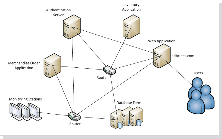
Figure 6.1 Logical and Physical Application Topology Map
Obviously, the process of application topology discovery is most efficient when using automated mapping tools in production. Even if there are no major reported issues, this activity should be pursued. The process is named continuous application topology discovery. Since a production environment keeps changing, subsequent mapping would depict a corresponding alteration in the topology.
Topology discovery is not only about using actual mapping tools and platforms. What if the proposed architecture is delivered in a diagram? What if there is no implementation? What if the design is merely conceptual? In this case, the application topology discovery and analysis process should be conducted by inspecting end-state architecture artifacts. These may include diagrams and a variety of charts depicting the logical and physical links of an application's environment.
Application Tier Distribution Topology Mapping
Another contribution of the application topology mapping is the capability to discover the physical distribution of an application in production. As discussed earlier in Chapter 5, not all application tiers may be located on a single server. Application components may be dispersed across an entire production environment.
The practice of packaging most application's components and deploying them on the same host would not necessarily ease production maintenance or reduce upkeep cost. Design principles, such as loose coupling, may call for separating complex N-tier application architecture elements and distributing them to different segments of a production environment. This may include the dispersal of security components and application management services, such as provisioning and configuration. Moreover, in other cases, not all applications' business logic services are deployed in the business tier. Reuse, components sharing, and scalability may be the reasons for splitting up an application's physical implementation.
Figure 6.2 illustrates the various tiers a Web application consists of. A diagram like this could divulge where the architecture components are located. As apparent, users typically operate remotely. Data repositories are distributed to an organizational data warehouse. Other tiers, such as the data access implementation, are also located apart from the business tier.
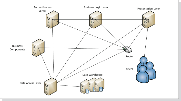
Figure 6.2 Logical Application Tier Distribution
Business Performance Discovery in Topology Mapping
One of the most compelling reasons to pursue the application topology mapping is to discover the key performance indicators (KPIs)1 of offered business services. This analysis can be accomplished by selecting the proper topology mapping tool. The application KPI could reveal a number of business perspectives that should not be ignored. While mapping application relationships, analysts should also take time to observe the actual contribution of an application to business imperatives. The task of discovering the business KPI of an application should center on a number of goals:
- Increase return on investment and revenue.
- Foster expenditure reduction of business operations.
- Improve customer satisfaction.
The KPI for an application service level agreement (SLA) would be a good place to start. Note a number of SLA measurements to observe:
- Application unavailability occurrences or production outages over the past six month or a year
- Slow application performance that may have resulted in customer dissatisfaction
- Additional operational cost allocated for repairing an application's response time
KPI for quality of application services is another aspect to examine during the topology mapping analysis:
- Does the application functionality meet business requirements? Would the customer be satisfied?
- Would inadequate services prompt customer complaints?
- Can the application handle a large number of consumers?
- Would application defects turn away customers?
- What would be the cost for enhancing the quality of services (QoS)?
- Would the application downtime for improving the QoS frustrate customers?
Evaluating business processes, service efficiency, and compliance with business strategy and mission are other KPI aspects that may be of interest to organizations. These measurements are vital to assessing the execution of business goals. Such discoveries typically lead to identifying gaps in business performance. As a result, these findings galvanize organizational initiatives to improve customer satisfaction.
In addition, to keep track of the state of a business, the enterprise should study the benefit of employing the balance scorecard.2 This performance measurement platform, offered by numerous tools, would enable management, architects, analysts, and developers to evaluate the effectiveness of a deployed application. The application topology mapping initiative, therefore, should include business performance discovery activities.
Mapping Application Dependency
The application discovery and analysis activity calls for studying the dependencies between an application and its operating environment. This task is vital to every architecture assessment. What is it all about? An application forms logical and physical dependencies in production to enable information exchange and business transactions. A logical dependency merely ascertains a contextual relationship, perhaps a business association or even links with consumers.
The physical topology does not necessarily depict such a conceptual bond. A physical dependency, in contrast, is shaped by network infrastructure and related devices, such as network connections formed by cables and routers. These logical and physical business associations and message paths could be easily spotted in a topology-map diagram, as illustrated in Figures 6.1 and 6.2. Indeed, topology mapping is a prerequisite to discovering application dependencies.
Application Dependency Discovery and Analysis Motivation
Why would anyone be interested in viewing application dependencies during the application discovery and analysis process? Why is such activity so intrinsic to application performance and maintenance? Why is the term “business continuity” so much about the way we design applications?
The answer to these questions is rooted in lessons learned from ill-designed application cases throughout decades of product development. Not long ago, monolithic applications used to dominate the computing landscape. Simply put, the term “monolithic” stands for huge implementations that offer a large amount of business processes. They are autonomous and deployed in central production locations. These applications are tightly coupled, single-tiered, undistributed, or federated. Furthermore, the monolithic application internal components depend so heavily on each other that the cost of separating them outweighs the benefits.
Similarly, two or more applications that are extremely dependent on each other could increase modification and maintenance costs and ultimately affect performance. With the expansion of today's production environments, architecture strategies call for distribution and federation of software. This is to avoid tightly coupled implementations, increase reuse, and simplify enterprise integration. Therefore, we ought to analyze the impact of application dependencies on architecture elasticity. The questions that follow explain the term “software elasticity”:
- Is the application design flexible enough to enable changes for business growth?
- Can a business compete with highly dependent applications in a production environment?
- Is then the proposed architecture practical?
Mitigating Interoperability Concerns
The increase of application dependencies introduces another strategic architecture concern: failure to achieve effective computing interoperability. That is, the design is not flexible enough to accommodate efficient communication between two or more distinct computing environments. This may include different language platforms, or even diverse hosting hardware and operating systems. To understand better the problem, remember that there could be enormous undertaking and affiliated costs to break down tightly coupled applications. If the separation of application components carries such a high price tag, organizations instead should consider employing interfaces and adapters for externalizing internal application business processes. But this in itself is another taxing endeavor.
Types of Application Dependencies
Unlike the monolithic implementation, where all parts of the architecture are typically bundled in a single physical location, distributed and federated enterprise architecture calls for accommodating physical communication over greater production distances. The challenge then would be to strike the right balance between overwhelming and fewer dependencies. Setting a measurable scale between a tight coupling and loose coupling design is what drives the dependency classification effort.
As discussed earlier, physical associations are driven by tangible configuration and actual integration structures. The term “physical” also implies that the routes between applications and the supporting network infrastructure and middleware entities are created to enable information exchange. Moreover, forming physical relationships in production is a costly integration endeavor. To assess the benefits and feasibility of the links, an application forms in production, classify the various associations and understand their contribution to application integration.
Discovering application dependencies is a vital activity that is not only about internal reliance of components on each other, but also connecting external entities, such as applications, middleware, and network infrastructure elements. Classifying application dependencies, internal or external, could uncover the motivation for creating physical associations in production. In due course, these relationships could be reconsidered to reduce asset dependencies. Therefore, this section explores common dependencies found in a distributed computing landscape and discusses the advantages and drawbacks of each association.
The sections that follow, therefore, elaborate on four types of application dependencies:
- Application private dependency. An application exchanges messages with a single software entity, such as a peer application, component, or middleware product.
- Application public dependency. An application exchanges messages with multiple message exchange peers or partners.
- External application dependency. An application trades messages with the environment, in which other applications and/or software components collaborate on executing transactions.
- Internal application dependency. Internal components of an application exchange messages.
Application Private Dependency
Privately formed application dependency only takes place between an application and an information trading partner. The term “partner” may pertain to a peer application, a database, a middleware product, a remote system, or even a cloud. Recall, this exclusive relationship forms only one message route between an application and another entity to fulfill a business transaction.
Furthermore, communication between an application and its related peer could be driven by two types of information trading patterns: two-way message exchange style and one-way message exchange style. These are explained in the sections that follow.
Two-Way Message Exchange Style: A Private Conversation
The two-way message exchange occurs when an application and its single information-trading consumer exchange messages. This implies that the message sender entity is always expecting a response. As apparent in Figure 6.3, the two-way communication takes place between application 1 and the DB. Request-response is the technical term for such data exchange method. This information trading activity is named “conversation.”
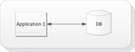
Figure 6.3 Application Private Dependency: Two-Way Message Exchange Style
As implied, this dialogue takes place between a message requester and responder. The technology behind this approach supports synchronous and asynchronous communication. The former implies that the sender must wait until the response returns. This pause of operation is known as blocking. With the latter, the sender continues with its duties until the response arrives. Timeout conditions could be set in both cases if a message is delayed.
One-Way Message Exchange Style: Private Communication
As mentioned, the one-way message exchange style, on the other hand, is another type of application private dependency (illustrated in Figure 6.4). This information transmission occurs when one party, either an application or a related consumer, sends a message without any reply expectations. Accordingly, in this illustration application 1 sends a private message to application 2. This approach is devised for business notifications—not business conversations. One side employs this approach to send periodical updates of any sort: for example, sending a bank account status or informing of a mortgage account outstanding. In these one-way examples, a message request-response implementation is not necessary.
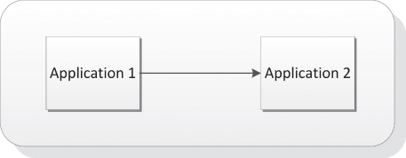
Figure 6.4 Application Private Dependency: One-Way Private Message Exchange Style
Application Public Dependency
In most instances, an application depends on more than one party to accomplish a business transaction. This relationship is named one-to-many. Although the private conversation, discussed in the previous section, is an easy method to exchange information, a more intricate relationship involves multiple message trading partners, namely public dependency. This widely implemented scenario entails that for completing a business activity, an application must exchange messages with multiple peers.
To understand better the application public dependency, review the simple example in Figure 6.5. Once a user completes an order online, the Book Order Application communicates with the Book Warehouse Application to verify if the book is in stock. If the book were not available, a request notification with a one-way alert message would be sent to the Book Publisher Application, asking for a replenishment.
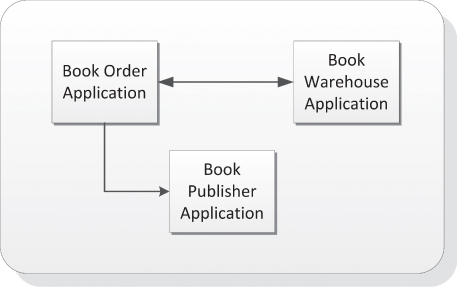
Figure 6.5 Application Public Dependency
Application Public Dependencies with Two-Way and One-Way Message Exchange Styles
Not only can application private dependencies utilize the two-way and one-way message exchange styles. Application public dependencies may also employ the two-way or one-way message trading patterns to accomplish a business transaction.
The decision of whether to use either the two-way or one-way message exchange style (or both) depends on design preferences. Since an application public dependency scheme is typically complex, of which multiple entities must trade information to accomplish a transaction, the two-way and one-way patterns may be utilized.
External Application Dependency
External dependencies, either private or public, pertain to relationships that an application forms with outside message-consuming parties. These associations also are about the integration of an application in a production ecosystem. The term “external” means that the analysis effort is not about the interrelationship of application-containing components. The sections that follow introduce common external application dependency examples.
Application Dependency on Data
An application may be highly dependent on external resources such as data source providers, data access component, or an organization's warehouse. The growing dependencies of applications on data storage facilities, repositories, and archiving platforms may have been raising organizations' concerns to new levels. The mounting demand for information is so staggering that enterprise architecture must come up with innovative solutions to reduce tightly coupled dependencies.
But no matter what the new solutions are, the traditional application dependency on data is still a burning enterprise issue. Solutions such as replicating data storages, and later synchronizing the information in an enterprise master repository, only increase application dependency on data.
Other efforts to decouple application from data introduce data proxies, such as data access layers, to isolate information from direct and tightly coupled access. Lastly, caching data is an additional method devised to separate an application from the main repository and speed up the CRUD (create, read, update, and delete) operations. This in itself is another approach for duplicating information that yields greater dependency on data.
Application Dependency on Proxies
Another example of application dependency on external software implementations is the overwhelming utilization of proxies. This approach fosters loose coupling design, by which an application communicates indirectly with its messages exchange parties. The increase of software intermediaries in production indeed enables the expansion of enterprise architecture. In different words, proxies are the means of distributing and federating software.
There is nothing wrong with the utilization of intermediaries to execute business transactions. Their contribution to application integration is vast. Software brokers, like an ESB or gateway for example, intercept messages for different purposes, such as security enhancements, credential passing, data augmentation, protocol conversions, data formatting, message routing, and more. Brokers offload these functionalities from applications and expose them to other enterprise applications for reuse.
With the growing scope of production environments, the role of software intermediaries has expanded considerably. Enterprise architecture practices have adopted the concept of message interception, enhancement, augmentation, and routing. This approach, however, increases application dependencies on proxies. As a result, messages must travel longer distances, interrupted by brokers, to reach destinations. Meanwhile, the long transport takes a toll on application performance and response time. An architecture discovery and analysis, therefore, should assess if the intercepting brokers introduce message delivery and performance challenges. Brokers may be the reason for slow application execution.
Application Dependency on Middleware and Network Infrastructure
This brings us to another topic that should be considered during the application discovery and analysis: middleware and infrastructure dependency. The vital operational support of an application in production by middleware and network infrastructure is undisputed. There is no application that can run without proper routing mechanisms, robust and scaled hardware, and network devices such as routers. The configuration efforts to integrate an application in production are immense and infinite. Constant integration initiatives take place because of new additions and enhancements to a production landscape.
These adoption and deployment tasks only increase external application dependencies on production. An application migration to another computing environment, therefore, has become a nightmare for production engineers. The struggle is to recreate an integrated environment for the relocated application. That is to say, the dependencies that an application has created with time are hard to replicate.
Internal Application Dependency
A self-contained application, such as a monolithic implementation, for example, does not tend to establish many external dependencies since its internal implementation is tightly coupled. Self-sufficiency, therefore, is a necessity because of an application's limited capabilities to collaborate with external message exchange partners. Namely, a tightly coupled application is made up of almost all components it needs to survive without relying extensively on external distributed applications. These internal and isolated functionalities may include message routing mechanisms, protocol conversion, security, user interface implementations and presentation mechanisms, data queuing and formatting, and more.
Accordingly, tightly coupled applications are not only hard to maintain, their reusability factor is typically low. To expose their business logic to outside service requesters, functionality externalization is therefore required. Externalization means adding interfaces or adapters that extend application capabilities, enabling outside consumers to utilize contained business processes. This undertaking typically takes place with legacy applications that are hard to decouple or decompose.
A tightly coupled application relies heavily on internal functions that are hard to separate because of the close-fitting dependency they form. The most common example of such design is the thick client or the rich Internet application (RIA). Each consists of a wide range of bundled internal capabilities and resides on a single host. These may include application business logic, user interface elements, protocol handling, and even routing capabilities. An abundance of similar examples could be found in almost every production environment.
One of the most common application design errors is the insertion of business logic into user interface implementation, in this case, a mix of business with user interface processes running from the presentation layer. An example is a loan calculator built in the loan application page. Or to fill in a customer profile page, user interface functions make calls to a repository. Obviously, such design does not comply with reusability best practices and should be rejected on the merits of tight coupling principles.
Reduction of unnecessary internal dependencies could be achieved by constructing reusable components and avoiding usage of inline functions. Therefore, an architecture proposition should support component-based implementation over library-based usage. A component-based design could be externalized and exposed to the outside world.
Application Dependency Patterns
To identify application dependencies, it is advised to rely on the various system fabric patterns discussed in Chapter 4. Although these patterns identify the arrangement of nodes and message paths in a system, they can also be used to discover and understand application dependencies. Fabric patterns can also depict the integration scheme under which an application exchanges messages in production. For reading convenience, the list of fabric patterns is provided here. For this purpose, we renamed them application dependency patterns:
- Community dependency pattern This is a point-to-point entity integration style, often named mesh pattern. An application that executes business transactions employs this style to connect to other applications, middleware products, and network infrastructure elements.
- Community center dependency pattern This arrangement, which resembles the network star topology, typically places an application in the center, where it exchanges information with the surrounding message exchange parties.
- Message transport dependency pattern In this scheme, an application is linked to a transport broker, such as an ESB, to trade messages with other entities on the network. Distribution and federation of applications could be achieved by employing this pattern.
- Family dependency pattern Application and related production entities are arranged in a hierarchical formation. Here, messages flow downstream from the parent application node to the offspring nodes, or upstream from the children nodes. Sibling nodes are able to communicate with each other, too.
- Circular dependency pattern A message path is formed with the arrangement of applications and its information trading parties in a circular structure. Circular business transaction is achieved with this style.
- Chained dependency pattern A linear business transaction is formed when employing this dependency pattern. Here, applications are chained to each other along with middleware, users, and network infrastructure elements.
- Bridge and crossroad dependency pattern This dependency patterns depicts the use of a broker to communicate to other applications or other entities on the network.
- Compound dependency pattern Compound patterns may consist of some or all mentioned patterns in this list.
Application and Supporting Environment Cataloging
The focus so far has been on application discovery and analysis. Application information has been gathered, and, in addition, we were able to compile facts and material about the supporting production environment. The task of cataloging, classifying, and indexing organizational assets, therefore, is now the mission. It is time to begin documenting the applications, middleware products, and network infrastructure elements.
This endeavor should not be pursued manually. There are countless asset management products on the market that offer cataloging and registration capabilities. These tools also keep track of production software and hardware versioning. Change and release control are among other additional features offered.
An effective asset management product should offer fundamental capabilities as described in the list that follows. Note that the itemized features not only provide technical information about software or hardware assets, but also make available related business facts:
- Ownership Identification of software or hardware owners and also sponsor information
- License Information that pertains to asset licensing terms, cost, and expiration
- Configuration management Current and historical configuration parameters applied to product installation, integration, and maintenance
- Inventory management Tracking in stack or on-site available licensed software components or hardware products
- Maintenance Information indicating life cycle maintenance activities for a product, such as installations, reconfiguration, migration, and applying patches
- Contract Contracts and vendor information stored to trace product upkeep agreements
- Procurement Initial cost of a product and its related components, manufacturer detail, and so on
- Expenditure Accumulative and periodic costs related to product maintenance in production
- Return on investment (ROI) management Typically measured in percentage, the incurred product revenue in relation to the initial and ongoing investment
- Status Identification of a product state in production, such as active, inactive, discontinued, removed, or relocated
Application Cataloging
When it comes to cataloging an application, the first thing to be done is to ascertain its identity. At least three identification keys would be required. First is a description of the overall application functionality and the solutions it provides to resolve business problems. Second, ownership and sponsorship information is another vital piece of information that can shed light on the application's purpose and strategy. Third, design and technical specifications are other artifacts that can elaborate on how the technological solution is devised to resolve business problems.
The contribution of the application cataloging is vital to development teams, production engineers, and executives. To achieve asset reuse, the application catalog can provide a wealth of information about an application or a system that is comprised of multiple applications. To decrease business process redundancy, architects should foster reuse of legacy implementations to leverage existing functionality.
Production engineers can also benefit from application catalogues. The entries in such a repository can provide valuable information for application deployment, configuration, and integration.
Consider the list of common fields in an application catalog for the establishment of application identity:
- Ownership and sponsorship This field is associated with the organization or executives who own an application. A sponsor may be a different entity.
- Publisher If an application is created by a software manufacturer, the publisher's information is provided.
- Development team These are application project managers, team members, and maintenance individuals.
- Business purpose This includes the business problem domain and concern statements.
- Business requirements These include an outline of business requirements and descriptions of business solutions.
- Services This field itemizes the solutions that a specific set of services offer.
- Line of business This is the affiliation of an application to a line of business or occupation.
- Business group This is the business division or departments an application is affiliated with.
- Application architecture class This field indicates the type of architecture or design pattern the application is based on, such as N-tier, client server, and more.
- Application tiers These include a list of application components and tiers, their location on a network, and solutions they provide.
- Service consumers These involve an identification of the application's consuming parties, such as online customers, business partners, and consuming applications or systems.
- Development platforms These include languages, integrated development environment (IDE), source code building tools, and libraries.
- Cost of ownership This is the cost to maintain, repair, and enhance an application in production.
Application Data Cataloging
Application dependency on data is fundamental to information sharing, persistence, and message exchange. Data cataloging, though, is one of the most significant activities that should be pursued during the application discovery and analysis. This activity entails the location and documentation of application-related repositories for their capacity, formats, data model, and more.
Cataloging data sources, such as data providers, data warehouses, or data proxies, is essential to understanding the dependencies of an application on external information. Data maintenance, such as provisioning, applying security, and modifying data models, is an additional reason to catalog data sources.
The cataloging activity should also include knowledge about application data produced internally. Monolithic applications, for example, tend to create, persist, and manage their private data. This internal information can be shared with the outside world by utilizing adapters or interfaces.
Consider the following list that includes fields of interest when pursuing the data cataloging activity:
- Data sources Types of data sources an application utilizes and their locations on the network
- Data warehouse Information about organizational data storage facilities, their locations, and access permissions
- Data repositories Information that pertains to database locations and other storage facilities that an application can access directly
- Data access layers Facts gathered about brokers or intermediaries that provide data access services and data manipulation capabilities, such as CRUD
- Data capacity Storage limit for a data source and the allowable usage capacity over time (typically yearly permissible capacity)
- Data exchange format Data layout and taxonomies used for message exchange and manipulation, such as ACORD, HL7, and XBRL
- Data model Diagrams or illustrations depicting the elements of the provided data and their relationships
- Data type Itemization of the various media a data source provides, such as text, video, and images
Cataloging Supporting Middleware and Network Infrastructure
Middleware and network infrastructure products support application operations in production. Cataloging production assets, then, would be an immense contribution to the asset and inventory management. More than anywhere else, the ever-changing production ecosystem must employ mechanisms to itemize and track network devices, platform components, servers, and a wide variety of middleware products. The number of organizational assets that take part in a production landscape could be overwhelming.
Organizations that conduct orderly fashion cataloging use the open systems interconnection of the International Standards Organization (ISO)3 model to collect information about organizational assets. This framework describes how devices operate on a network and how hardware and software enable the communication between computers. The ISO model consists of seven stacked layers. The network infrastructure and middleware cataloging initiative, however, refers only to first four layers:
- Physical—the electrical and physical networking devices that carry the data across a network
- Data link—the mechanisms used to transmit data in a network, including topologies and transmission protocols
- Network—switching and routing network mechanisms
- Transport—the hosts and the methods they use to transport the data from end to end
The two lists that follow depict fields that capture infrastructure and middleware information. First, the infrastructure cataloging information:
- Manufacturer Information about the hardware manufacturer
- Model Hardware model or sub-model, including the manufacturing time stamp
- Serial number Hardware serial number
- Device type Identifies the role of a network device, such as routing, switching, bridging
- Contract details Contract affiliated with the rent and/or maintenance of a network device or host
- Business organization The business entity that is utilizing the infrastructure
- Cost of ownership The cost of maintaining, repairing, and enhancing infrastructure assets in production, including also the ongoing energy and air-conditioning expenditure, replacements, and upgrades
- Operating system The operating system a host uses
- Capacity
CPU, memory, and disk capacity information for a particular host
For middleware products, consider the list that follows:
- Middleware category Identifies the role of a middleware product, such as an ESB, gateway, or proxy
- Publisher Manufacturer details and date of creation
- Version Middleware version
- Contact Contract affiliated with the maintenance of a middleware product
- Interfaces Identification of middleware communication protocols and adopters
- Capabilities The functionality related to a middleware product, such as message routing, data formatting and transformation, security enforcement
- Consuming applications A list of the applications consuming a middleware product