
Chapter 14
End-State Architecture Stress Testing Driven by Pressure Points
Here we are again, continuing the discussion about the preparation for the end-state architecture stress testing. The methods of discovering pressure sources in an integrated production environment have been covered so far. By now it is clear that pressure-prone areas in an end-state architecture could be caused by a wide range of software and hardware conditions that simply clot or congest network sections. The analogy to a city power grid is indeed a good example that explains the phenomena of a computing environment slowdown or complete shutdown. Unfortunately, organizations are too familiar with such circumstances that only add chaos to existing production environments and threaten business profitability.
Discovering pressure-prone areas in end-state architecture (discussed in Chapter 13), either as a proposition on paper or already operating in a production environment, is a good start. As discussed, the analysis renders sections that could potentially harm business transactions on a network. This effort narrows down the vast production spaces into interest areas for the end-state stress testing initiative.
But the end-state architecture stress testing could not pinpoint the exact locations on a network or focus on a software entity if merely a trouble-prone area is called out. We need to do better than this.
The Justification for Inserting Pressure Points
The mission would then be to drill down into a pressure-prone area and mark one or more pressure points. By discovering pressure points, the end-state architecture stress testing effort would focus on particular production entities or specific network aspects that may be the source of pressure. This simple idea of targeting specific end-state architecture elements and avoiding trivial areas that are believed to be harmless to production is a valuable proposition.
Remember, inserting pressure points in an end-state architecture does not mean that the environment as a whole is marked as subject for stress testing. That is not the case. Pressure points are just intersections. They should be regarded as targeted spots for the stress testing efforts. The higher perspective then should reveal an end-state architecture environment that includes multiple pressure points. Collaborative pressure points on such a grand-scale design would uncover how strained the end-state architecture is and if its environment would be able to meet design specifications.
Therefore, ask these questions to confirm if the overall end-state architecture environment would indeed meet technical requirements:
- Will the collaborative pressure points affect systems and applications performance?
- Have too many pressure points been discovered in the end-state architecture?
- Where are the majority of the pressure points located? Are they pointing to systems? Applications? Components?
- Are there too many pressure points marking troubling spots on the network, suggesting insufficient network bandwidth?
- Do the majority of the pressure points suggest that asset integration would introduce performance risks?
- Do the pressure points call for further investigation into the mounting strain on organizational data sources?
- Are security measurements in end-state architecture causing applications to slow down?
Inserting Pressure Points in an End-State Architecture
It is clear that inserting pressure points into an end-state architecture should be applied in the already defined pressure-prone areas. This means that every discovered pressure point should be established within the boundaries of potentially strained areas in the end-state architecture. These stressed ranges are largely discussed in Chapter 13.
The end-state architecture stress testing effort then may start right after the pressure points have been located. The process of positioning a stress point in the grand scale design is simple. However, there could be many reasons for placing pressure points in particular strained spots. Some are affiliated with concerns about application response time and message exchange performance. Other reasons may be related to insufficient network bandwidth capacity. Moreover, a pressure point could focus one's attention on implementation errors that could form communication bottlenecks. Obviously, integration of assets in production may yield pressure points that must be given attention, too. The list of reasons is typically long. A meticulous analysis should determine the weight of a pressure point in the overall end-state architecture.
Focus on the Chief Stress Testing Mission: End-State Architecture Verification
Architecture structural, behavioral, or volatility reasons could inflict risky pressures in production. However, no matter what the reasons are behind positioning a pressure point on an end-state architecture map, we still need to focus on the fundamental motivation for conducting stress testing. The chief justification is rooted deep in the incremental architecture verification process. Proving that an end-state architecture would actually perform in production would be required to certify the environment's fitness.
Therefore, inserting pressure points at potential transaction breaking points is the current mission.
There is one more architecture verification aspect to focus on before moving on to an example demonstrating the insertion of pressure points. Recall that two leading types of pressures exist: internal and external. The former suggests that the pressure emanates from internal components of an application or a system. The latter, on the other hand, is related more to environment influences, in which architecture elements are linked to each other and collaborate to achieve a business goal. One would argue that internal pressures are the cause for external pressures. For example, a glitch in a software component could harm the communications with an external entity such as an ESB. This justifies the claim that both pressures, internal and external, are highly dependent. However, there may be instances where internal pressure would not necessarily prompt external ones.
End-State Architecture Pressure Points Use Case Study
Now it is time to turn the attention to Figure 14.1 to inspect the pressure points inserted in the end-state architecture pressure prone areas. Note that these areas are defined first in Figure 13.6. Obviously, these pressure points are fictional. They mark strained areas in the design merely to present a schematic concept. In addition, the rendered pressure points, P1 to P4, represent points of interest for the end-state architecture stress testing.
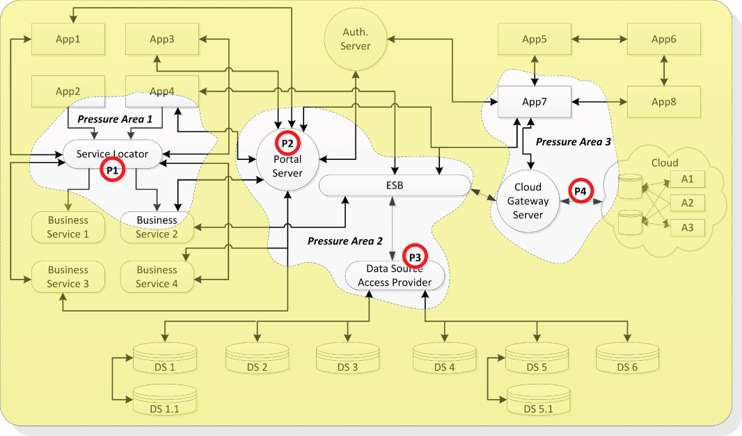
Figure 14.1 End-State Architecture Pressure Points Example
Let us break down Figure 14.1 into the discovered pressure points to understand why each was inserted in these particular locations:
- Pressure point P1. Positioned on the service locator in pressure area 1
- Pressure point P2. Located on the portal server in pressure area 2
- Pressure point P3. Placed on the data source access provider in pressure area 2
- Pressure point P4. Sited on the message route that connects the gateway server and the cloud
Pressure points are affiliated to concerns. These are typically architecture junctions representing points of strain on network infrastructure, hardware, message routes, and software implementations. As discussed throughout this chapter and largely in Chapter 13, one must be aware that the chief types of pressure-inducing sources are architectural structures, software behaviors, and volatile regions. Therefore, consider the reasons behind positioning these pressure points in the end-state architecture, as depicted in 14.1:
- Structural Pressure points P1 (in pressure area 1) and P2 (in pressure area 2) are placed in the center of two centralized sub-architectures. P1 is positioned on the service locator, a hub that offers common services in a hub-and-spokes architecture formation. The reason is obvious: Hubs are typically sensitive to environmental pressures that are generated by their subscribing consumers. P2 was positioned on the portal server for the same exact reason. It is regarded as a point of concern for the stability of the architecture because of its potential to intercept the messages of more consumers. Another aspect to be concerned about is that P2's central position in the star-like structure may buckle under in the face of bombardment of oversized message loads.
- Behavioral Pressure point P3 is placed on the data source access provider, a middleware product located in pressure area 2. In enterprise production environments, data access services offer a wide range of functionalities, all of which are designed to shield repositories and data providers from the rest of the organization. Among such capabilities are CRUD (create, read, update, and delete) and other security features to protect the information. This behavioral aspect of the data source access provider may be subject to architecture pressures because of the demands of unanticipated or planned consumers.
- Volatile In our case study, pressure point P4 in pressure area 3 is positioned because of volatility concerns due to recent changes to the cloud interfaces. Note that P4 points to the message route connecting the cloud gateway server and the cloud. This would be a point of interest to the end-state architecture stress testing. Modifications applied to the cloud entry point may affect a large community of users and processes trying to access services. Placing such a prone-to-change spot in a strategic location is mandatory.
Methods of End-State Architecture Stress Testing
The establishment of pressure points in an end-state architecture is a major milestone. The discovery of these strained locations paves the road to a structured stress testing effort that must only focus on predefined troubling and risky spots in a production landscape. Pinpointing performance concerns in precise network locations would simplify the methods by which we are about to assess an end-state architecture fitness.
The process of end-state architecture stress testing must start with an analysis, during which the environment is studied thoroughly. The end-state architecture vision and mission are clear. And the integration of systems and their internal assets, such as applications, middleware products, and network infrastructure is understood.
The discovered pressure points must be prioritized next. Some may be regarded as negligible spots of interest to the stress testing. Others may be recognized as critical. Once the pressure points have been identified, a detailed stress test plan should be carved out, offering engineers a meticulous stress testing road map. The stress testing plan should also include the approaches taken to accomplish the examination of the end-state architecture environment. (Stress testing methods are discussed in the Stress Test Approaches section later in this chapter.) Moreover, the employment of specialized tools is fundamental to every stress-testing initiative. The selection of such tools must be conducted to be able to meet stress test plan requirements.
Establish Pressure Point Failure Conditions
There are no industry pressure point risk standards for organizations. What is defined as a pressure risk in one institute could not be applied to another. Setting a threshold for entering the zone of risk when pressures are applied on end-state architecture elements such as network, systems, or applications is indeed subjective to an enterprise. Only an organization, though, is able to define for itself the risk conditions that should be avoided. These specifications should be documented in a nonfunctional requirement paper.
In this section we then offer only certain quantifiable aspects that are affiliated with risks of pressure on organizational assets. This proposition includes a risk model for breaking points in an end-state architecture. The term “breaking point” pertains to the exact starting time at which an implementation, such as a system or its affiliated components, or applications, may buckle or underperform under the weight applied to a pressure point. Although the intention here is not to define measurable aspects of a pressure risk, the aim is to establish ranges of risks, a model that could be applied to an end-state architecture stress testing effort.
A Risk Model for Breaking Points
To view the range of risks associated with pressures applied on a pressure point in an end-state architecture, let us examine Figure 14.2. As is apparent, this risk model illustrates three distinct ranges of pressure risks that could be traced over time:
- Low pressure risk
- Medium pressure risk
- High pressure risk
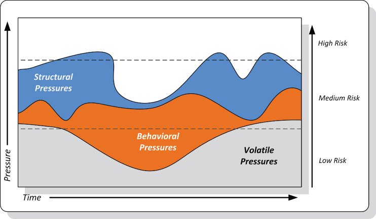
Figure 14.2 Breaking Points Risk Model
These risk scopes on the area chart set three boundaries for pressure levels. For each of them, an organization should specify the actual ranges in a nonfunctional requirements document. Clearly, the low pressure risk level identifies a range that would not raise breaking point concerns. As shown, the volatile pressure source, illustrated here as an example, is measured within this range. The behavioral and structural pressure sources, though, pose higher risks to the environment.
The medium pressure risk level, on the other hand, indicates that a risk that is carried by a stress on pressure points should be still acceptable to an organization. To some institutions, the term “medium” rings a warning bell, a cautionary reminder that mounting pressures on end-state architecture elements could cross the borderline into the high-risk level. Precautionary measures are typically applied to restrain the pressure risk to the low-level range. Therefore, finding the structural and behavioral type of pressures, as depicted in Figure 14.2, in the medium-risk category should be an uncomfortable end-state architecture performance proposition.
The structural sources of pressures, as depicted in Figure 14.2, break through the higher end of the medium-risk scope into the high-risk range. No organization should accept pressure risks that fall under the high-risk category. An end-state architecture that contains architecture pressure points classified as high-risk should not be sponsored or supported. There is no defense for deploying or maintaining end-state architecture when parts of it are known to be extremely vulnerable to environmental pressures.
Consequences of Pressure Risk Levels
With every risk defined in the breaking points model, there are consequences that an organization should be prepared for. An environment with no risk at all is an idyllic ecosystem that can rarely be found. Even the lowest pressure risk level could still wreak havoc on production. To understand the costs of pressure point failures, let us classify them into three main categories:
- Low risk pressure. The consequences of such risks are typically related to unstable and unpredictable performance of software entities. At this risk level, systems and/or application performance do not necessarily halt. Erratic functionality behavior with pauses could be observed.
- Medium risk pressure. At this risk level, performance degradation and sluggish message exchange could affect a number of dependent software entities. The integration between architecture elements is at risk, of which all connected software entities suffer from slow response time and information exchange delays.
- High risk pressure. This risk level typically results in total system halt, severely congested network, and shutdown of business applications.
Stress Test Approaches
The stress testing may start now. Before we start we must know, however, what methods should be employed to run stress tests for the end-state architecture. Some fundamental aspects must be remembered when accomplishing these fitness tests:
- An end-state architecture stress test should be driven by a detailed plan that specifies time frames, message load, preconditions, and assumptions and predictions about the outcome.
- The chief goal of an end-state architecture stress test is to verify if its corresponding environment is elastic, steady, durable, and sustainable. The grand scale design must be proven and certified.
- An end-state architecture stress test must employ tools with message injection capabilities. The term “message injection” refers to what is known as load testing, during which streams of data are directed toward a software entity, a server, or a network infrastructure asset to test its stability and capacity. Posting generated messages through message exchange routes in a variety of frequencies and strengths would enable control and monitoring on released pressures toward pressure points.
- The targets of an end-state architecture stress test must be predefined pressure points that are rendered by analyses of architectural structures, environment behaviors, and volatile breaking points.
- The simulated pressure should be measured by messages per second. A message size should be benchmarked equally across an end-state architecture to maintain standard pressures.
- The three methods of end-state architecture stress testing, as described in the sections that follow, should be performed to meet the certification requirements.
Recovery Discovery
The recovery discovery method for stress testing is depicted in the self-explanatory Figure 14.3. Time over pressure is the ratio that depicts how the test should be conducted. Specifically, simulated messages should be released into the network toward pressure points in three sequential bursts or more. As depicted in the illustration, each burst in the succession applies stronger pressure than the previous one. Moreover, between each pressure eruption, a pause should take place to measure the aftermath. This recess should give the opportunity to inspect the reaction to the applied pressure on various architecture elements, such as systems, applications, or components.
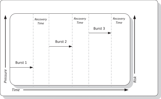
Figure 14.3 Recovery Discovery Stress Testing Method
This method of stress testing measures the state of recovery from different strengths of pressure bursts. The ultimate goal would then be to discover the time it takes for an architecture element to revert to its normal state. For example, an application running in a virtual machine typically operates under normal conditions if the garbage collector is not suppressed and able to reclaim unused memory space without slowing down the implementation. Again, this approach of stress testing would allow measuring the time lapse between the end of a pressure burst and the beginning of operation recovery.
Another aspect that should be tested is if the communication between pressure points and their environment has recovered. If architecture elements resume operation with normal message exchange rate within an acceptable time frame, the recovery process is considered successful. This test would verify if the integration between production assets meets design specifications.
Ask the questions that follow to confirm if indeed the recovery discovery stress testing on an end-state architecture concluded successfully:
- Did the pressure points on architecture elements, such as components, applications, and middleware products resume normal operation during message burst breaks?
- Was the resumption of operation within an acceptable timeframe?
- Did the message exchange between production environment entities recover?
- Was any pressure point shut down after or during pressure bursts?
Breaking Points Discovery
The breaking points discovery stress testing method is devised to accomplish one vital sustainability challenge driven by a principal question: Would an end-state architecture pressure point halt normal operation during a continuous and increasing pressure? That is, a stress test fails if a pressure point halts its activities during a steep climb in a strengthening pressure, as depicted in Figure 14.4. This simple concept of applying increasing pressure on an architecture element, such as message routes, middleware, or applications reveals if end-state architecture would indeed perform flawlessly in production.
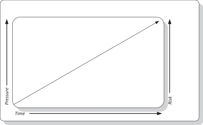
Figure 14.4 Breaking Points Discovery Stress Testing Method
Unlike the recovery discovery, discussed in the previous section, the breaking points discovery approach calls for continuous pressure that halts only when a breaking point in the architecture is discovered. It is advised to raise the pressure level applied to pressure points beyond the specification for sustainability in the nonfunctional requirements. For example, if such requirement calls for a pressure point to process 1,000 messages per second, then the breaking point discovery stress test should double the pressure to 2,000 messages per second. Again, the stress test should not end there if a breaking point has not been discovered. The pressure must be increased even beyond the parameters in a stress test plan.
The rule of thumb therefore suggests that after the an end-state architecture stress testing the discovered breaking points should be cleared by mending the mounting pressure conditions. That is, the end-state architecture should not include any breaking points discovered above the allowable sustainability parameter (measured in messages per second) in the nonfunctional requirements document. This is one of the most important stipulations of the end-state architecture verification process. Therefore, no end-state architecture should be further funded or supported in production until all unacceptable breaking points are cleared away. Removing breaking points in such a grand-scale design should be accomplished by testing again the decomposed architecture segments and correcting critical design flaws by pursuing again the design substantiation process (discussed in Chapter 12).
Ask the questions that follow to insure that the breaking point discovery stress test was completed successfully:
- Have any breaking points been discovered during the stress test?
- What was the pressure intensity when a breaking point was discovered?
- Was the breaking point ascertained beyond the acceptable pressure indicated in the nonfunctional sustainability requirements?
- What is the organization's allowable breaking point pressure (in messages per seconds)?
Durability Discovery
Durability is one of the most fundamental requirements of the end-state architecture verification process. An architecture environment must be proven solid and maintain normal operation during different periods of the day. For example, an application would be required to operate under higher pressures, naturally occurring during message exchange peak time. The ultimate test to confirm stability and business continuity is to conduct the durability discovery, as illustrated in Figure 14.5.
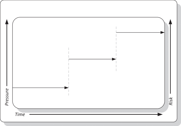
Figure 14.5 Durability Discovery Stress Testing Method
Testing operations continuously during different periods of the day and under a variety of pressure strengths could uncover end-state architecture flaws. This simple test is worthwhile. It could expose environmental design defects that were hard to catch during the design substantiation process (discussed in Chapter 12).
Remember, unlike with the breaking point discovery stress test, during which it is expected to encounter shutdown of architecture elements, the durability discovery process is all about testing the fitness of an end-state architecture during normal and peak hours. Obviously, any design flaw discovery that fails in an architecture environment should only encourage efforts to correct it.
Once again, durability parameters in the nonfunctional requirements document must indicate the allowable pressure (messages per second) that an architecture element must sustain. Again, the durability parameters should pertain to different times of the day. A benchmark should be set for slow, busy, and peak times.
Ask the questions that follow to insure that the durability discovery stress test is successful:
- What were the durability parameter values (messages per second) in the nonfunctional requirements?
- Did the durability discovery stress test results surpass the durability parameters?
- Did any of the end-state architecture environment elements halt during the stress test?
- Did any of the end-state architecture elements slow down during the stress test?
- During which period of the day did a pressure point buckle under the persistent pressure of message exchange?