
In the previous chapter, we had to consider many diverse technologies and protocols that are in use today in Industrial Internet scenarios. However, thankfully within the access network segment we are on far more traditional network territory with long-established and dominant technologies and protocols. Therefore, in this chapter we will look briefly at the communications technologies that are likely to be implemented in an Industrial Internet deployment and the corresponding protocols and applications that are deployed as middleware to facilitate the specific requirements for some Industrial Internet use-cases.
The Access Network
The access network in the IIC’s architecture of the Industrial Internet is purely a transitional transport network with the purpose of interconnecting the diverse networks and protocols, which exist in the complex proximity network with the standard IP networks found in enterprise and business environments. Therefore, the technologies and protocols that we will examine are used to interconnect the domains and transport data back and forth and these are the same technologies and protocols commonly deployed in the enterprise.
The sole purpose of the access network is to aggregate data and to backhaul it from the device gateway to the system and applications within the operational and management domain . As this domain is purely IT, it follows that it will use a traditional IT architecture, based on IP and Ethernet. Therefore, the principle task for the components in the access network is to transport IP over Ethernet as efficiently as possible, and that will require gigabit Ethernet trunks over copper, optical fiber, or even wireless and high-speed Ethernet switches.
Ethernet
So what is an Ethernet frame? A data packet on an Ethernet link or LAN is actually an Ethernet packet and it has an Ethernet frame as the payload. An Ethernet frame is represented in Figure 6-1.

Figure 6-1. Ethernet frame
An Ethernet frame has the very first field as the destination MAC address and the second field is the source MAC address. However, there is another field of interest that is the frame following the MAC source address. This frame is called the 802.1q tag.
VLANs
As traffic will be aggregated from multiple edge networks, we will have to deploy some form of tagging in order to track which traffic belongs to which edge network. By tagging the traffic, we can effectively segregate each individual stream and provide a virtualized network. This technique in Ethernet is called a VLAN or Virtual LAN . A VLAN provides basic levels of segregation, security, and efficiency as the size and range of broadcast domains are reduced—although the number of broadcast domains actually increases—and this reduces the amount of broadcast traffic and the corresponding host responses, considerably.
VLANs are a popular way for a network administrator to segment a layer-2 switched network by configuring the local Ethernet switches with VLAN IDs and then placing the selected ports into the designated VLANS. This is great for local administration of a single switch. However, what if the requirement is for the VLAN to span the entire network of 1,000 switches? Then the solution requires VLAN trunking and a VTP management domain.
When configuring VLANs on an Ethernet switch, the ports can be either access ports, which directly connect to a host, or trunk ports, which connect to another switch. There is another difference though—an access port can only accept and forward packets from one VLAN, whereas a trunk port accepts and forwards packets from two or more VLANs.
A trunk port is a point-to-point link to another switch or router that forwards traffic to several destinations. Trunk ports therefore carry information from several VLANs across the same physical link, which allows VLANs to span the network. However, for a packet to leave its local switch where the VLANs are known—the local VLAN database—there has to be some way in which the packet’s VLANs membership can be determined by another switch.
The way an Ethernet network handles this is through tagging the individual packets with a VLAN ID. Every packet entering the VLAN port on the local switch is tagged with a VLAN identifier. Therefore, every packet that is in a VLAN will carry with it a special tag declaring its local VLAN ID that other switches on the network can inspect and forward accordingly. The switch does this by placing a tag in one of the fields in the Ethernet frame.
This VLAN identifier is how an Ethernet frame can be marked to be different from other frames. The VLAN tag defines its VLAN membership. Now the network switch, when receiving a packet, can look inside and check the frames value for not just the source and destination addresses but also the VLAN ID. Additionally, administrators can now group hosts from different network segments many switches away from one another into the same virtual LAN as if they were sitting on the same local switch.
When a network grows, maintaining and administering VLAN architecture becomes a burden as VLAN configuration information has to be configured and updated across all the switches in the network. Administrators then need to use VTP (VLAN Trunking Protocol ) or something similar in order to maintain consistency across the network. VTP assists in maintaining, renaming, updating, creating, and deleting VLANs on a network-wide basis. VTP minimizes configuration inconsistencies such as incorrect names or VLAN types.
IP Routing
The alternatives to high-speed Ethernet switching (layer 2) are to do IP routing (layer 3) between the various edge networks and the operational and management platforms. Routing is generally much slower than Ethernet switching, as routing is predominantly a software function with many lookups of IP routing and forwarding tables.
IP routing does provide for subnetting of the IP address space, which provides similar functions as the Ethernet VLANs discussed earlier, in that they provide segregation and security, and they break up large broadcast domains. Subnets are not required with IPv6, which is one of its great advantages.
Routing, if pure speed of delivery is not the ultimate goal, has many distinct advantages, such as it provides more granular control over traffic flows, traffic management, and quality of service (QoS) .
Furthermore, in this instance, we have assumed that the edge networks and the operational and management platforms are in the same location or at least within a layer-2 switching LAN, as is usually the case in commercial and manufacturing. However, what if these edge networks are remote, perhaps 100s of mile away, geographically dispersed around the country, or even the globe? How would we construct our access network then?
Access Networks Connecting Remote Edge Networks
Routing over WAN links is the most obvious choice and we will discuss those options later in the WAN section. However, we can still in most cases use fast Ethernet switching. For example, we can connect remote office, production sites, or factories using a service provider’s MPLS network (multiprotocol label switching ). The service provider can design layer-2 VPNs across their MPLS network to provide what is effectively a layer-2 overlay, which will connect all the remote locations as if they were on the same layer-2 segments. This service can be termed as a virtual private wire or LAN. Similarly, dark fiber—other’s spare capacity—can be utilized in metro and urban areas to interconnect data centers using optical long distance point-to-point Ethernet interfaces.
Carrier Ethernet
Another industrial variant of Ethernet is Carrier Ethernet and it is commonly used in industrial scenarios for interconnecting switching rooms and sub-stations. An example is the way mobile operators interconnect their switch rooms at their remote and geographically dispersed tower locations. By using carrier Ethernet or MPLS, mobile operators can switch backhaul traffic from the towers as reliably and deterministically as they once did with synchronous technologies such as ATM and TDM.
Whichever method we chose, whether routing or switching, the end goal is the same—to deliver the traffic from the edge networks to the operational and management platforms. Once again there are many ways to achieve the same goal; it all really depends on the specific requirements as to which is the better solution.
Profinet
Switching and routing performance may be sufficient for most enterprises and commercial activities and use-cases. However, in manufacturing, the non-deterministic performance of these Ethernet and IP solutions fall short of the requirements. Industrial solutions especially in manufacturing requires highly robust, reliable, and real-time solutions. The problem is that IP is just not quick enough in that it introduces too much latency (delay) or deterministic, in so much as it introduces too much jitter.
Industrial Ethernet covers many of these issues and a leading open standard for Industrial Ethernet in manufacturing is Profinet.
In an early chapter, we discussed briefly the differences between standard Ethernet and Industrial Ethernet, so we will not revisit those areas. However, the reason we are discussing Profinet in this section is to show why and how Profinet—as a leading Industrial open standard—resolves the issues of latency and jitter that bedevils standard switching and routing.
Profinet is 100% Ethernet compatible and adheres to IEEE standards so can be deployed in a flexible line, ring, or star topology using copper and fiber-optic cable solutions. It also enables wireless communication with WLAN and Bluetooth.
However, Profinet also includes intelligent diagnostic integrated tools for field devices and networks. These tools provide important information regarding the status and health of devices and the network, including a display of the network topology. Profinet delivers this diagnostic information through acyclic diagnostic data transmissions, which allows redundant high available equipment to react automatically to any predicted failure, enhancing the stability and availability of the manufacturing plant.
However, what is of interest to OT network designers is how Profinet handles data transmission. Here we see that Profinet handles all communications over the same cable. The communications can range from simple control tasks to highly demanding motion-control applications. Indeed, for high-precision closed-loop control tasks, deterministic and isochronous transmission of time critical data is handled with a jitter of less than 1μs (see Figure 6-2).
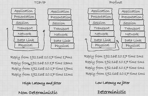
Figure 6-2. Profinet’s deterministic nature
Synchronous Real-Time
Profinet achieves its deterministic performance because, like all Ethernet switches, it uses its MAC address to communicate with other Ethernet devices over the local LAN. By not using an IP address, Profinet can reduce latency and jitter considerably. However, Profinet also provides deterministic (very little jitter) by the way it manages data flows. What Profinet does is split data transmissions into three types:
Cyclic I/O data transmitted in real time
Acyclic data transmissions used for parameter data and diagnostic information, which is not in real time
Alarms, which is another real-time transmission channel for urgent maintenance required status alarms
By using dedicated cyclic I/O data channels for input and output, a Profinet I/O controller can set sub-channels and determine the clocked phase of each sub-channel within a range of 250μs to 512ms. Therefore, the I/O controller can control the transmission latency and amount of jitter by setting and monitoring the cyclic I/O data channels to, for example, 1ms.
Therefore, Profinet controllers are capable of handling applications with the most stringent deterministic demands. They can minimize the jitter through synchronous cyclic I/O data transmissions. However, for all the devices to handle synchronous data transmissions with a maximum deviancy of 1μs, they must have a shared clock.