Redox-Active Inorganic Materials for Redox Flow Batteries
Bo Hu, Jian Luo, Camden DeBruler, Maowei Hu, Wenda Wu and T. Leo Liu
Utah State University, Logan, UT, USA
- 1 Introduction
- 2 Iron–Chromium Redox Flow Battery
- 3 Vanadium Redox Flow Battery
- 4 Zinc‐based Inorganic Redox Flow Batteries
- 5 All‐iron Redox Flow Battery
- 6 Polyoxometalate and Heteropolyacid Redox Flow Battery
- 7 Polysulfide–Polyhalide Redox Flow Batteries
- 8 Other Nonaqueous Inorganic Redox Flow Batteries
- 9 Perspective
- 10 Conclusion
- 11 Acknowledgments
- 12 Abbreviations and Acronyms
- References
1 Introduction
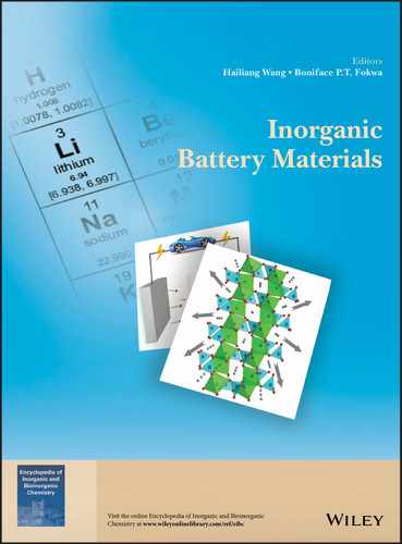
Extensive consuming of fossil fuels within less than 200 years has resulted in the truth that concentration of CO2 in the atmosphere increased dramatically from 280 ppm at the beginning of industrial revolution in the nineteenth century to about 408 ppm in 2018,(1) which has caused serious substantial environmental impacts. Utilization of renewable energy sources such as solar and wind energy represents a sustainable and environmentally benign strategy to alleviate the world's severe dependency on traditional fossil fuels.(2) It is estimated that 68% of today's electrical energy is supplied from fossil fuels while only 3% from renewable energy technologies.(3) However, under the pressure of global warming and climate change, more attention and efforts have been focused on renewable energy utilization. For example, global wind power generation capacity is expected to reach 474 GW in the year 2020, about five times increase as compared to 2007.(3) In order to manage the intermittent and fluctuating nature of solar and wind energy, cost‐effective technologies for energy conversion and storage are in urgent need.(2–4) Among numerous energy storage technologies, redox flow batteries (RFBs, Figure 1) have been recognized as a promising technology to overcome the intermittency of renewable energy and supply reliable electricity to electricity grids with a scale up to MW/MWh.(3–5)
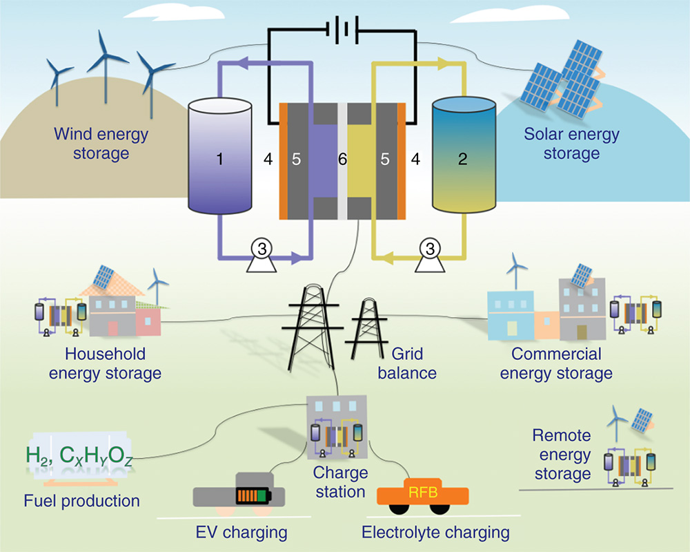
Figure 1 Graphic representation of diverse applications and cell components of redox flow batteries (RFBs). 1. Anolyte reservoir; 2. catholyte reservoir; 3. pumps; 4. current collectors; 5. carbon electrodes; 6. ion exchange membrane
RFBs operate in the general mechanism of a rechargeable battery by using redox‐active chemicals dissolved in liquid supporting electrolyte solutions stored in two reservoirs (Figure 1). The redox‐active liquid electrolytes are termed as anolyte in the anode side and catholyte in the cathode side, respectively. A separator (ion exchange membrane or porous membrane) sandwiched between two electrodes allows the crossover of supporting electrolyte while prohibiting the crossover of active materials. During charge/discharge processes, redox reactions (Equations 1 and 2) happen on the surface of the electrode while supporting ions (such as H+, Na+, K+) as charge carriers migrate through the ion exchange membrane to balance the charge. Thereby, a flow battery is able to store or release electrical energy. The unique cell architecture of RFBs empowers a number of attractive technological merits for large‐scale energy storage in comparison to traditional static rechargeable batteries. First, RFBs can modulate their energy (the volume of the electrolyte reservoirs) and power (electrode surface area) independently, which makes the power supplying more facile to manage.(3–5) Second, RFBs can operate at high current and high power densities due to fast electrochemical kinetics and high conductivities of aqueous supporting electrolytes. Third but not last, RFBs represent a safe energy storage technology by using nonflammable aqueous electrolyte materials. In addition to centralized grid‐scale energy storage, RFBs with their technological merits are suitable for relatively small‐scale decentralized energy storage applications including residential and commercial power backups, remote micro‐grids, charge stations for electric vehicles, and fuel productions (Figure 1). It is worth noting that it is promising to develop high energy density RFBs as direct power sources for electric vehicles.
Volumetric energy density as a key parameter for a RFB which stands for the amount of energy that can be stored in the battery per liter electrolyte (Wh L−1). The volumetric energy density of a RFB is determined by its cell voltage (V) and charge capacity (Ah L−1) as shown in Equation 3. Charge capacity is further determined by the concentrations of active materials, and the number of electrons involved in the redox reactions given by Equation 3, where n is the number of electrons, F is the faradic constant, c is the concentration of the more soluble electrolyte material between the anolyte and catholyte, μ is the volume factor for the full cell and defined as (1 + Vlarger/Vsmaller) (Vsmaller is the volume for the more soluble electrolyte and Vlarger is the volume for the less soluble electrolyte).

The efficiencies of RFBs are manifested by coulombic efficiency (CE), voltage efficiency (VE), and energy efficiency (EE) as defined subsequently. CE is the ratio between discharge capacity and charge capacity. CE is an important indicator that can reflect active material crossover and irreversible side reactions if it is apparently lower than 100%.(6) VE is the ratio between discharge voltage and charge voltage, which reflects the overpotential of the battery during charge/discharge process. The multiplication of CE and VE gives EE.
Active materials applied in RFBs are very diverse such as redox‐active metal salt,(7,8) nonmetal inorganic materials,(9) organometallic compounds,(10–12) organic molecules,(13–16) and even polymers.(17) Among the various active materials, a few inorganic systems (Fe–Cr, Zn–Br2, all‐vanadium) have been demonstrated for large‐scale application. Here, we present a review to discuss inorganic materials applied in RFBs with a primary focus of their most recent technological advances in aqueous inorganic RFBs. With an overview of the battery performance of different redox‐active inorganic species, a brief perspective toward improved battery performance is also presented.
2 Iron–Chromium Redox Flow Battery
Iron–chromium redox flow battery (ICRFB) stands for the first true redox flow battery (RFB) developed in the 1970s at National Aeronautics and Space Administration (NASA) as a possible energy storage means for deep‐space missions.(18) Fe2+/Fe3+ and Cr2+/Cr3+ couples in hydrochloric acid are employed in an ICRFB providing a cell voltage of 1.18 V (Equations 123).


Although ICRFBs have been extensively studied in the last decades, two issues remain to be overcome before it fully meets the performance and cost requirement matrices for broad market penetration. First, unlike the fast Fe2+/Fe3+ redox reaction on bare carbon felt, Cr2+/Cr3+ redox reaction shows poor kinetics.(19) Although high‐temperature operation condition could facilitate the Cr2+/Cr3+ redox reaction, it would also result in significant parasitic energy loss, complexity of the system, and cost increase.(19) Hydrogen evolution reaction (HER) is severe for acidic ICRFBs, which not only reduces the CE, but also causes the state of charge (SOC) of positive and negative electrolytes to be imbalanced over prolonged cycles, eventually causing capacity decay.(20) Therefore, in order to operate ICRFBs efficiently at room temperature, catalysts are required to facilitate the Cr2+/Cr3+ redox reaction and suppress the HER simultaneously. To counter this issue, catalysts, such as Bi and Au–Ti alloy, are deposited on the electrode surface to enhance the electrochemical kinetics of the Cr2+/Cr3+ redox reaction while alleviate HER.(21,22) Second, active materials crossover is another problem for ICRFB, which can cause irreversible capacity decay because of unsatisfactory ion selectivity of membranes. This issue could be solved by using a mixed electrolyte of Fe and Cr salts for both half‐cells. The capacity decay during long‐term operation can be recovered by simply remixing the positive and negative electrolyte.(20) This strategy is also used for other RFB systems, such as all‐vanadium RFB.(23)
In addition to the fundamental study, extensive efforts have also been made to install the ICRFB system for the purpose of large‐scale energy storage. EnerVault demonstrated the world's largest ICRFB system up to 250 kW/1 MWh in California, USA.(24)
3 Vanadium Redox Flow Battery
3.1 All‐Vanadium Redox Flow Battery
Since the invention of the all‐vanadium redox flow battery (VRFB) by Skyllas‐Kazacos et al. in 1980s, the all‐vanadium RFBs have been receiving massive studies and continuous commercialization.(25) Several VRFB systems have been installed, including the world's largest redox flow battery system rated at 60 MWh (15 MW for 4 h) in the Minami‐Hayakita substation of Hokkaido Electric Power Co., Inc. (HEPCO) by Sumitomo Electric Industries, Ltd.(26) An even larger system is under construction by Rongke Co. in Dalian (China), with a scale of 200 MW or 800 MWh.(27) The all‐VRFB represents the most mature RFB system hitherto for large‐scale energy storage in terms of well‐developed battery chemistry and system components.


The VRFB use the V2+/V3+ redox couple (−0.26 V vs standard hydrogen electrode (SHE)) for the anode side and the V4+/V5+ redox couple (+1.0 V vs SHE) for the cathode side, giving a theoretical cell voltage of 1.26 V (Equations 789). Crossing through a Nafion membrane, protons work as the shuttle to balance the charge of the electrolytes. In order to operate the VRFB with V4+/V5+ and V2+/V3+ redox reactions, a pre‐charging step is required in most cases.(28) Particularly, the same VOSO4 (in H2SO4) electrolyte is distributed to catholyte and anolyte reservoirs with a volume ratio of 2 to 1. Then the cell is pre‐charged with a SOC of 100%. At this point, VO2+ (V4+) is fully oxidized to VO2+ (V5+) in the cathode side and V4+ is fully reduced to V2+ in the anode side. Subsequently, half of the fully charged catholyte (VO2+) is removed for charge balancing and a fully charged VRFB with V5+ and V2+ species on each side is obtained.(28) V2O5 is also being used as the raw materials to replace the pricy VOSO4. To solve the solubility issue of V2O5 in sulfuric acid, two methods were initially developed to produce VRFB electrolytes from V2O5 powder.(25) The first method involves chemical dissolution of the vanadium pentoxide powder by reaction with sulfur dioxide to produce a solution of V4+ in sulfuric acid. The second method involves the electrolysis of suspended V2O5 powder in the negative half‐cell of an electrolysis cell to produce a mixture of V3+ and V4+ species (also defined as V3.5+).(25)
From the intrinsic properties of vanadium redox chemistry, VRFBs have displayed many advantages for large‐scale energy storage. (i) Long lifetime: due to particularity of single element configuration, the cross‐contamination could be solved by electrolyte remixing.(5) By doing this, the capacity loss could be restored effectively. This advantage helps VRFB to display the long calendar and cycle lives with more than 200 000 cycles already demonstrated in a NEDO funded demonstration system in Japan, and over 10 years of operation already completed for another VRFB system in Europe.(29) (ii) High EE: electrolytes used in VRFBs are highly conductive because of using strong acidic supporting electrolytes. Typically, VRFBs can achieve more than 80% EE with a current of 100 mA cm−2. (iii) High power performance: because of high electrolyte conductivity and a high cell voltage, VRFBs can deliver high power density up to several hundred MW cm−2, representing one of the most powerful RFBs known to date. Despite these salient features, challenges are also existing, which hinder VRFBs' practical applications. Vanadyl (IV) sulfate (VOSO4) is the most common active material for VRFBs, which is highly soluble in water (up to 4 M). However, adding sulfuric acid, as the supporting electrolyte to provide higher conductivity, would dramatically decrease its solubility (1 M in 7 M H2SO4) due to the common ion effect. With increasing H2SO4 concentration, the total sulfate concentration increases, which shifts the equilibrium to lower dissociation of vanadyl sulfate.(30) On the other hand, the V(V) ions in the positive half‐cell electrolyte can undergo thermal precipitation to form V2O5 at elevated temperatures of 40 °C (Equations 10 and 11).(19,31) Therefore, to balance the stability and the solubility of the vanadium active species, the concentration of vanadium and total SO42 − is usually controlled at less than 2 and 5 M, respectively.(4) This operation concentration determines an energy density of less than 25 Wh L−1.(5)
In order to improve the solubility and stability of the active materials, strategies have been conducted such as using mixed supporting electrolyte and adding additives. In 2011, scientists at Pacific Northwest National Laboratory reported sulfate–chloride mixed acid electrolytes for all‐vanadium RFB application.(7) Wang and coworkers found that the mixed electrolyte supported the vanadium ion dissolution with a high concentration up to 2.5 M in the presence of 2.5 M SO42 − and 6 M Cl−, which indicated an energy density increase of 70% compared to traditional pure H2SO4 supported VRFBs with a wider operation window from −5 to 50 °C. In addition, using density functional theory, and 51V&35Cl NMR, V5+ was proved to be existing as a neutral complex as VO2Cl(H2O)2 is more stable than VO2(H2O)3+ cation owing to the prohibition of the formation reaction from VO2(H2O)3+ to H3VO4 (Figure 2). This dimer complex has a higher thermal stability due to its resistance to the deprotonation reaction which is the initial step of V2O5 formation (Equation 10), thus it can stabilize the V5+ electrolyte. Moreover, the vanadium redox couples in mixed electrolytes demonstrated improved reaction kinetics while remaining as highly reversible as in the pure sulfate supporting electrolyte. Following the mixed HCl/H2SO4 electrolyte study, Kim et al.(32) suggested a vanadium chloride solution for all‐vanadium RFBs. For the chloride‐based electrolyte, thermally stable ions such as the vanadium dinuclear species of [V2O3·4H2O]4+ or dinuclear‐chloro complex of [V2O3ClH2O]3+ also display high solubility (2.3 M) within a large temperature range from 0 to 50 °C. Besides HCl, other forms of acids, such as phosphoric acid, EDTA, and CH3SO3H, have been also examined as VRFBs' supporting electrolyte.(33,34) However, they are not as effective as HCl. Organic and inorganic additives have also been explored to increase the solubility and stability of vanadium active species. Skyllas‐Kazacos et al. investigated additives including sodium hexametaphosphate (SHMP), K2SO4, Li2SO4, and urea.(33) Supersaturated 4 M vanadyl sulfate solutions were prepared and the stability was evaluated. In 2016, they reported a high energy density vanadium redox battery employing a 3 M vanadium electrolyte using K3PO4, H3PO4, (NH4)2SO4 as additives.(33) The VRFB was subjected to 90 charge/discharge cycles and no precipitation or capacity loss was observed in the presence of 1 wt% H3PO4 and 2 wt% ammonium sulfate.

Figure 2 (a) The structures of V5+ monomer complexes in the sulfate and the sulfate–chloride mixed solutions. (b) 51V NMR spectra of a mixed sulfate–chloride solution. (c) 35Cl NMR spectra of a mixed sulfate–chloride solution.
[Adapted with permission from Ref. (7) © Wiley‐VCH, 2011]
Actually, additives cannot only serve as solubility boosters and stabilizers for vanadium redox‐active materials but also catalysts for the redox reactions, thus improving the VRFBs' EE. Some inorganic ions such as Sb3+ and Bi3+ have been added into the anolyte to improve kinetics for V2+/V3+ and V4+/V5+ redox reactions.(35,36) The improved electrochemical performance proved to be ascribed to the prominent catalytic effect of metal particles, which are simultaneously electrodeposited onto the surface of graphite felts (GFs) during operation of a flow cell and facilitate charge transfer process. Wang et al. employed electrolytes containing Bi3+ to improve the performance of a VRFB.(35) With the adding 0.01 M Bi3+, the EE was significantly improved by about 11%. A surface image of GF modified with Bi nanoparticles (NPs) at different magnifications after cycling was obtained from field emission scanning electron microscope (FESEM), scanning transmission electron microscopy (STEM), and high‐resolution transmission electron microscopy (HRTEM) as shown in Figure 3. The formed Bi NPs were only found at the negative electrode and facilitate the redox reaction of the V2+/V3+ redox couple which was confirmed by the minimizing of the peak–peak separation of the V2+/V3+ redox couple in cyclic voltammetry (CV) experiments (Figure 3d). In addition, the charge/discharge overpotential was also dramatically reduced, and the specific capacity was doubled.

Figure 3 (a) FESEM images of GFs modified with Bi nanoparticles at different magnifications after cycling; (b) STEM image of Bi nanoparticles in the anolytes resulting after cycling; (c) HRTEM images of Bi nanoparticles; (d) cyclic voltammograms with glassy carbon as working electrode in solutions vanadium electrolyte with or without BiCl3.
[Reprinted with permission from Li, B.; Gu, M.; Nie, Z.; Shao, Y.; Luo, Q.; Wei, X.; Li, X.; Xiao, J.; Wang, C.; Sprenkle, V.; Wang, W., Bismuth Nanoparticle Decorating Graphite Felt as a High‐Performance Electrode for an All‐Vanadium Redox Flow Battery. Nano Lett. 2013, 13 (3), 1330–1335. © American Chemical Society 2013]
Shi et al. reported that the EE was increased from 57.5% to 67.1% at a current density of 120 mA cm−2 by introducing 5 mM Sb3+ into the negative electrolyte.(36) In3+, Cr3+, and Mn2+ ions were applied as additives to improve redox kinetics of V4+/V5+ couple. In these cases, metal cations, other than metal NPs, promote the charge transfer, redox reaction reversibility, and diffusion coefficient of the V4+ and V5+ species. As we can see, by adding Bi3+ and Sb3+ additives, electrodes were modified with metal catalysts.
In fact, extensive studies have also been conducted to modify the electrode with electrochemical catalysts, such as carbon materials, transition metal oxides, and redox mediators to meliorate performance for VRFBs.(37–40) In addition to poor redox reaction kinetics, the sluggish interfacial charge transfer from electrode surface to vanadium species is also responsible for EE loss of a VRFB.(39) Wang et al. introduced prussian blue (PB) and a prussian blue analog (PBA) with identical redox potentials to VO2+/VO2+ and V2+/V3+ onto cathode and anode electrode as electron mediators to facilitate the charge transfer process.(40) During the charging process, the oxidized PB reacts with VO2+ to generate VO2+ on the cathode electrode, and V2+ is reduced to V3+ by reacting with the reduced PBA on the electrode. Tafel plots shows that the PB‐modified glass carbon electrode has an exchange current density (3.8 × 10⁻⁴ A cm−2) two orders of magnitude as high as the pristine electrode (3.0 × 10⁻⁶ A cm−2), implying a considerably enhanced kinetics of the modified electrode. This strategy boosts power density of a VRFB from 178 mW cm−2 with a bare carbon electrode to 373 mW cm−2 with a modified electrode.
3.2 Hybrid Vanadium Redox Flow batteries
As we mentioned previously, V5+ species in the catholyte for the VRFBs tends to form precipitation. Moreover, due to the high oxidation ability and corrosiveness of V5+ in the VRFB, the availability of compatible separators is very limited.(19) The high‐cost Nafion membranes are still the best choice for an all‐vanadium RFB. In order to overcome the problem of high‐cost separators and avoid the issue of cathodic precipitation, researchers have made efforts to replacing V4+/V5+ contained catholyte with some less oxidative materials while V2+/V3+ solution is still used as the anolyte, thus resulting hybrid vanadium RFBs. Skyllas‐Kazacos(41) employs a polyhalide solution in the positive half‐cell electrolyte and a V2+/V3+ redox couple as the negative half‐cell electrolyte. During charging, the bromide ions in the positive half‐cell are considered to undergo oxidation to form the polyhalide ion Br2Cl−. The formal potential of this couple is about 0.8 V versus SCE. When combined with a formal potential of around −0.5 V versus SCE for the V2+/V3+couple in the chloride supporting electrolyte, an overall cell potential of approximate 1.3 V was obtained. It was also revealed that in the electrolyte with higher Cl− concentration, V2+/V3+couple redox kinetics is better.
Fe–V hybrid RFBs were first designed by the scientist at PNNL to overcome both the anodic issues of traditional Fe–Cr RFBs as we discussed previously and cathodic problem of the all‐vanadium RFB. The combination of Fe2+/Fe3+ and V2+/V3+ redox couples gives a cell voltage of 1.02 V which is lower than the VRFB (1.26 V).(19) However, rapid fading in the cell capacity (70% capacity decay within 50 cycles) was observed caused by the crossover of the Fe/V ions through the membrane during the charge/discharge processes, which also caused a lower columbic efficiency (93%) throughout the cycling. Fortunately, this problem was effectively solved by using a mixed electrolyte of Fe2+ and V3+ ions for both anode and cathode. When 1.25 M Fe/V in 2.3 M HCl mixed solution was used in each half‐cell, 95% capacity was retained within 50 cycles. In the following study, Wang and coworkers explored an optimized condition using 1.5 M FeCl2/1.5 M VOSO4 in 3.0 M HCl. Combined with low‐cost microporous separator, the Fe–V RFB showed stable cycling performance and high EE (62% at −5 °C).(42) In addition, HCl–H2SO4 mixed acid was also examined as a supporting electrolyte for Fe–V RFBs.(43) With the combination of 1.5 M Fe and 1.5 M V in 1.5 M sulfate and 6.8 M total chloride solution, the redox flow cell achieved an EE greater than 80% at 50 mA cm−2 and no capacity fading over 100 cycles employing Nafion 212 as the membrane. Impressively, even with a piece of low‐cost polyethylene microporous separator, the Fe–V RFB also delivered satisfactory cell efficiencies and stable energy density over 50 cycles.
4 Zinc‐based Inorganic Redox Flow Batteries
VRFBs have been well developed and successfully commercialized. However, the total system capital cost of VRFBs is above $400 per kWh where the cost of electrolyte accounts for 55%, which is way beyond the target $150 per kWh set by U.S. Department of Energy (DOE).(44) In order to reduce the cost of the flow battery system, it is necessary to utilize low‐cost active materials. Zinc has a much larger production up to 12 million tons per year, comparing to 76 thousand tons/year for vanadium. Meanwhile, the price of zinc metal is only one‐tenth of V2O5,(45) which makes zinc very attractive as an anode material in RFBs. Another advantage of zinc electrolytes is the high solubility of zinc salts. For a typical VRFB, the operation concentration of vanadium is normally less than 2 M. In a zinc‐based RFB, the concentration of zinc salts can be higher than 5 M which brings in a superior energy density compared to VRFBs. Different from VRFBs which have liquid phase redox reactions for both cathode and anode, in a Zn‐based RFB, zinc deposition/stripping happens on the surface of the anode electrode, defining zinc‐based RFB as a hybrid RFB system.(4) By minimizing the volume of anolyte, the volumetric energy density of the zinc RFB can be boosted up to a very high level. However, the Zn electrode has limitations of low current and power densities due to the formation of Zn dendrites. In addition, in contrast to all‐liquid RFBs (such as VRFB), power, and energy of such hybrid systems are not fully decoupled.(4)
For a zinc‐based inorganic RFB, a zinc salt (ZnCl2, ZnBr2, and ZnI2) is dissolved in water and used as anolyte. The catholyte materials for zinc RFBs can be halogen salt (Br− and I−),(46,47) low valent metal salt (Ce3+, Fe2+),(48,49) and organic molecules and polymer materials ((2,2,6,6‐tetramethylpiperidin‐1‐yl)oxyl (TEMPO)).(50) It is worth noting that separator selection is crucial for Zn‐based RFB. Anion exchange membranes (AEMs) feature quaternary ammonium species on the pore surface which lead to a side reaction/precipitation of Zn2+.(51) Therefore, AEMs could lose their ion conductivity in the presence of Zn2+. In this part, we introduce the Zn‐based RFB systems which have been extensively investigated.
4.1 Zn–Halogen Redox Flow Batteries
As the first zinc–halogen battery example, a Zn–Cl2 RFB was demonstrated in 1921, while the system received only a few development until 1980s due to the high‐cost challenge of chlorine storage.(4) Comparing to Zn–Cl2 RFBs, Zn–Br2, and Zn–I2 systems have been realized to be much more practical due to easier storage, lower volatility, and better electrochemical redox kinetics of Br2 and I2 than Cl2.
4.1.1 Zn–Br2 Redox Flow Battery
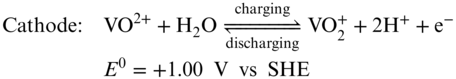
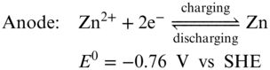
Along with vanadium RFBs, Zn–Br2 system is another commercialized RFB platform with a kW/kWh−1 scale.(52) The battery has a cell voltage more than 1.8 V and energy density as high as 60 Wh L−1. Bipolar ZnBr2 electrolyte is used for both anode and cathode in a Zn–Br2 RFB. The electrochemical reactions are described in Equations 12–14.


During battery charging process, zinc deposits on the cathode electrode while Br− anions are oxidized into Br2 in the anode side. Although ZnBr2 has a solubility of more than 4 M in water, liquid Br2 is slightly soluble in water (0.35 mg mL−1). As a serious safety concern, Br2 vapor pressure will keep increasing during batteries' charging process, which is very dangerous as bromine is well known to be extremely toxic and corrosive to human bodies.(4) In addition, the low solubility of bromine would also limit the practical energy density of the full RFB.(53) In order to suppress the Br2 vapor releasing, researchers have been exploring complexing reagents, such as quaternary ammonium bromide, to reduce the amount of free liquid or gas type bromine.(54,55) Zn–Br2 RFBs are operated at acidic conditions ca. pH 4. At an acidic pH, zinc anode corrosion and HER become more dominant and lead to lower CE.(52) Besides, zinc dendrite formation is also severe, especially at high charge/discharge current densities. Thus, the operation current density (<20 mA cm−2) is much lower than VRFB.(52)
4.1.2 Zn–I2 Redox Flow Battery
The emerging of Zn–I2 RFB is regarded as an alternative system to address the highly toxic and corrosive issue and performance drawbacks of Zn–Br2 RFBs. Comparing to Zn–Br2 RFBs, Zn–I2 batteries have several impressive advantages. (i) In aqueous solution, ZnI2 has a better solubility (7 M) than ZnBr2 (4 M) which results in a higher theoretical energy density of Zn–I2 RFBs than Zn–Br2 RFB.(47) (ii) I2 is solid at room temperature with a much lower vapor pressure than liquid bromine. Besides, I2 can react with I− fast and generate highly soluble polyiodide I3−, which ensure a good capacity utilization of Zn–I2 RFBs although 1 equiv of I− need to consumed as the complexing reagent. (iii) The I3−/I− redox couple has a better redox kinetic than the Br3−/Br− redox couple.
As an analogue of the Zn–Br2 RFB, a Zn–iodine RFB employing ZnI2 as a bipolar electrolyte was first reported by Wang et al. as shown in Figure 4.(47) The resulted battery displays an open circuit voltage (OCV) of about 1.3 V while it is dependent on the concentration of the active materials (decreases from 1.43 V to 1.22 V with the increasing concentration of ZnI2 from 0.5 to 5.0 M). By minimizing the volume of the anolyte, the battery has a superb theoretical energy density about 322 Wh L−1 which surpassed the LiFePO4‐based lithium ion batteries (ca. 223 Wh L−1 based on cell level). A Nafion membrane was applied as the separator which proved to be effective to minimize I− anions crossover as a high CE about 99% was obtained. It is worth noting that the electrolyte showed a slightly acidic pH 3–4 at 0% state‐of‐charge which worked for suppressing both dramatic hydrogen evolution and Zn(OH)2 precipitate formation. The flow cell was charge–discharge cycled within a range of current densities between 5 and 20 mA cm−2. The energy efficiencies decreased from ca. 91% to ca. 76% as the concentration of zinc iodide increased from 0.5 to 3.5 M, which was attributed to the decrease of electrolyte conductivity. Using 5 M ZnI2 as the electrolyte, the battery demonstrated an energy density as high as 166.7 Wh L−1 under a real flow condition for 40 stable cycles. One of the most challenging issue for Zn‐based RFBs is the dendrite formation which could penetrate the separator and cause serious self‐discharge. In order to alleviate the dendrite formation during the Zn–I2 RFB's charging process, ethanol was applied as an additive. The addition of an alcohol could induce ligand formation between oxygen on the hydroxyl group of an alcohol and zinc ions, which ameliorates the zinc dendrite issue. Meanwhile, the ethanol–water mixed solvent expanded the stable electrolyte temperature window from −20 to 50 °C. In addition, to further improve the dendrite, a small current density of 10 mA cm−2 was also applied to cycle the battery which is much lower than most of the aqueous RFB systems. From this study, we can recognize that it is impossible to utilize all the I− active materials in Zn–I2 RFB systems with pure bipolar ZnI2 electrolyte due to the sacrificed 1 equiv I− for the formation of polyiodide species.

Figure 4 (a) Schematic representation of the proposed Zn‐iodine RFB system; (b) CV of 0.085 M ZnI2 on a glassy carbon electrode; (c) cycling performances for discharge energy densities and capacities of the cell with 3.5 M ZnI2 and Nafion 115 as membrane under the current density of 10 mA cm−2; (d) the charge and discharge energy densities as a function of the concentration of I−. The inset lists concentration versus energy density of several current aqueous RFB chemistries for comparison.
[Source: (47), https://www.nature.com/articles/ncomms7303?page=2. Licensed under CC BY 4.0]
As we stated earlier, aiming to improve the energy density of RFB, strategies are required either increasing the concentration of redox‐active material or enhance the cell voltage. Following Wang and coworkers' study on Zn–I2 chemistry, Lu et al. applied bromide ions (Br−) as a complexing agent to stabilize the iodine, forming iodine–bromide ions (I2Br−) as shown in the electrochemical reactions in Equations 15–17, which frees up a portion of iodide ions and increases the capacity.(56)

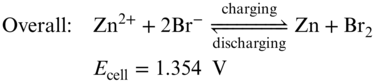
Applying this strategy, they demonstrated a novel zinc/iodine–bromide battery to achieve an energy density of 101 Wh L−1 for the full cell (or 202 Wh L−1 for the cathode half‐cell), which is among the highest energy densities achieved for aqueous flow batteries to date. As shown in Figure 5, both centrosymmetric I3− and asymmetric I2Br− tend to have a linear (or nearly linear) trihalide structure, which is thermodynamically stable. Despite the high solubility of the iodide redox species, the overall capacity of this battery is still limited by the zinc negative electrode due to the dendrite formation.(4) Since the same electrolyte is used for both half‐cells, the electrolyte crossover is mitigated.
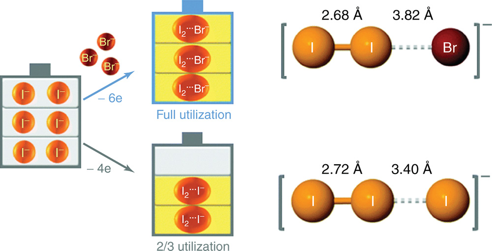
Figure 5 Concept illustration of bromide as the complexing agent to stabilize iodine. Bonding length of the polyhalide ion of zinc polyhalide is obtained from first‐principles density functional theory calculations.
[Reproduced with permission from Weng, G.‐M.; Li, Z.; Cong, G.; Zhou, Y.; Lu, Y.‐C., Unlocking the capacity of iodide for high‐energy‐density zinc/polyiodide and lithium/polyiodide redox flow batteries. Energy Environ. Sci. 2017. © Royal Society of Chemistry 2017]
Intuitively, the second strategy to enhance Zn–I2 RFBs energy density is boosting the cell voltage. Zn‐base redox couples exhibit dramatical redox potential difference between acidic and alkaline conditions. In acidic electrolyte, Zn2+/Zn redox pair shows a redox potential of −0.76 V versus SHE, whereas in alkaline solution Zn(OH)42 −/Zn redox pair displays a redox potential at −1.26 V versus SHE. Meanwhile, the redox potential of I3−/I− couple is not pH dependent. Keeping the I3−/I− couple as the catholyte, Chen and coworkers simply replaced the Zn2+ anolyte of Zn–I2 RFBs with the alkaline Zn(OH)42 − electrolyte and increased the cell voltage by 0.47 V as shown in the redox reaction (Equation 18) and Figure 6.(57) Started with the charged state, the designed batteries applied a Zn plate and KOH solution in anode side, and prepared neutral potassium polyiodide solution as catholyte by simply dissolving KI and I2 in water. Nafion 117 was employed as the separator to mitigate the crossover of Zn(OH)42 −, I−, I3− and other species. During discharging process, zinc metal oxidation reaction occurs at the anode in an alkaline KOH anolyte, yielding soluble potassium zincate (K2Zn(OH)4) (Equation 19).


Figure 6 (a) The open‐circuit‐voltage between the conventional and designed alkaline Zn–I2 RFB; (b) cyclic voltammograms of 0.1 M ZnAc2 with 3 M KOH (green curve) and 0.1 M KI (yellow curve) on a glassy carbon electrode; (c) representative charge/discharge curves at different electrolyte concentrations; (d) influence of the discharging current density on the achievable specific capacity and energy density.
[Reproduced with permission from McCulloch, W. D.; Yu, M.; Wu, Y., pH‐Tuning a Solar Redox Flow Battery for Integrated Energy Conversion and Storage. ACS Energy Lett. 2016, 1 (3), 578–582. © Royal Society of Chemistry 2017]
K+ cation instead of Zn2+ shuttles between two electrodes to balance the charge. A small amount of zinc and iodide species were also detected at cathode and anode sides, respectively, which indicates slow active materials crossover. The high‐energy‐density Zn–I2 RFB was demonstrated with a catholyte concentration of 6 M, which resulted in an energy density of 330.5 Wh L−1. However, the battery was only cycled with 44% depth of the state of discharge for 10 cycles. The RFBs with 2 M and 4 M I3− anolyte faced fast capacity and energy density decay within 10 cycles which might be due to long‐term compatibility between the alkaline anolyte and the neutral I3−/I− catholyte. We hypothesize that during the cycling, there would be a pH change in both anolyte and catholyte. The pH decrease of the anolyte could result in the formation of Zn(OH)2 precipitate while the pH increase of the catholyte could lead to the chemical decomposition of I− to iodate (IO3− ).(58) Besides, dendrite formation was another issue for the demonstrated RFB which caused a fluctuation of EE from 65% to 80% at the current density of 20 mA cm−2.
Overcoming the dendrite effect in Zn–I2 RFBs is crucial to meliorate batteries' CE and prolong batteries' lifetime. By means of adding additives such as alcohol, and applying low current density (<20 mA cm−2), the dendrite formation can be suppressed yet not be avoided especially after long‐term cycling. Very recently, Li et al. reported a concept of a zinc–iodine RFB with dendrite self‐healing capability which ensures the battery's long cycle life (1000 cycles) and high power density (Figure 7).(59) A piece of porous polyolefin membrane was employed as the separator. To eliminate the cross‐contamination and improve the cycling life, a mixed electrolyte of KI and ZnBr2 was used as both catholyte and anolyte. The pores in the membrane can be filled with a solution containing I3− that can react with zinc dendrite. Therefore, by consuming zinc dendrite, the battery can self‐recover from micro‐short‐circuiting resulting from overcharging, although the CE was sacrificed to a certain extent. Owing to the excellent conductivity of both electrolyte and separator, the battery was operated at a high current density (80 mA cm−2) and still could maintain an EE of 82%. More impressively, a stack with 700 W output was demonstrated for 300 charge/discharge cycles, which displayed a promising future for practical application. However, long cycling stability is a big concern for this system, which might be attributed to hydrogen evolution in the anode side.

Figure 7 Self‐healing concept for a Zn–I2 RFB with a porous membrane.
[Reproduced with permission from Xie, C.; Zhang, H.; Xu, W.; Wang, W.; Li, X., A Long Cycle Life, Self‐Healing Zinc‐Iodine Flow Battery with High Power Density. Angew. Chem. 2018, 57 (35), 11171–11176. © Wiley‐VCH 2018]
4.2 Zn–Fe Redox Flow Batteries
Because of high abundance and low cost of both zinc and iron metals, Zn–Fe RFBs are one of the most promising systems which could meet the capital cost target of $150 per kWh for grid‐scale energy storage by 2030 projected by the Department of Energy, United States. The first demonstrated Zn–Fe RFB was based on the Zn–ferrocyanide chemistry in alkaline solution.(60) However, further development of the alkaline Zn–ferrocyanide RFB was hindered due to the challenges of high cost of Nafion membrane, zinc dendrite formation, and ZnO precipitate generation from the supersaturated Zn(OH)42 − electrolyte. Early in 2018, Li et al. developed a nonfluorinated ion conductive membrane and 3D carbon felt electrodes for the Zn–ferrocyanide RFB.(61) The low‐cost ion selective membrane showed an ultra‐high selectivity for hydroxide anion and a good mechanic resistance against zinc dendrite. The 3D carbon felt electrodes worked as a guidance for Zn deposition/stripping which suppressed the formation of dendrite. The battery displayed a good cycling stability and an impressive energy density of 82.8% at 160 mA cm−2. Although Zn–ferrocyanide system is very energy efficient, this demonstrated system only utilized capacity of 65% and less than 50% at 100 and 160 mA cm−2, respectively. The low active materials utilization could also contribute to the stable cycling stability by compensating the chemical decomposition of ferrocyanide compounds at alkaline conditions, bringing concerns for their applications in alkaline RFBs.(62) Half‐cell studies of ferrocyanide compounds have been conducted by Liu et al.(61) to examine their chemical and electrochemical stability at different pH conditions. It is revealed that the redox couple functions best at neutral or near neutral conditions (Figure 8). Dramatic capacity decay of the redox couple was observed in a strong alkaline KOH electrolyte (pH = 14), which is due to the chemical decomposition associated with the CN− ligand dissociation. It is believed that the ligand dissociation can eventually lead to the formation of Fe(OH)X (X = 2 or 3).
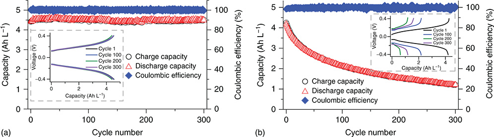
Figure 8 K4Fe(CN)6/K3Fe(CN)6 half‐cell cycling performance at different pH conditions. (a) pH 7.2; (b) pH 14.
[Reproduced with permission from Gong, K.; Ma, X. Y.; Conforti, K. M.; Kuttler, K. J.; Grunewald, J. B.; Yeager, K. L.; Bazant, M. Z.; Gu, S.; Yan, Y. S., A zinc‐iron redox‐flow battery under $100 per kW h of system capital cost. Energy Environ. Sci. 2015, 8 (10), 2941–2945. © Royal Society of Chemistry 2015]
Comparing to ferrocyanide compounds, iron salts (such as FeCl2, FeSO4) have much higher solubility in water. Fe3+/Fe2+ redox couples display a good redox reversibility and a redox potential of +0.77 V versus normal hydrogen electrode (NHE) which is 400 mV more positive than ferrocyanide. These merits make iron salts promising candidates as cathode materials in Zn–Fe RFBs. Since iron cations are not compatible with basic electrolytes, acid conditions are needed to avoid the formation of iron hydroxide precipitate and improve Fe3+/Fe2+ redox reaction kinetics.(63) In recent years, a few acidic Zn–Fe batteries have been developed.(63,64) However, all of them showed poor cycling stability due to active materials crossover and HER. Aiming to overcome these obstacles, Gong and coworkers put forward a hybrid Zn (alkaline)–Fe (acidic) three channel system with a low capital cost of $100 per Wh as shown in Figure 9.(65) Originated from the concept of the multiple ion‐exchange membrane design, the alkaline Zn anolyte and NaCl solution in the middle chamber was separated by a piece of Nafion 211 membrane while an A901 AEM was applied between the cathode side and the middle chamber. This assembling of a two‐separator‐three‐chamber system enables different pH values in the cathode side (FeCl2 in HCl) and the anode side (K2Zn(OH)4 in KOH), which effectively solved the problems of both active materials crossover and the HER side reaction. The demonstrated system showed a low resistance of 2.3 Ω cm2. When the flow rate was increased to 100 mL min−1, battery's overall EE can be boost up to 74% at 80 mA cm−2. With a high voltage of 1.99 V, the battery was capable of delivering an impressive power density of 676 mW cm−2. However, only 20 charging/discharging cycles were reported. Long‐term cycling reliability of this system still needs to be verified. It is believed that the hybrid alkaline/acidic Zn–Fe RFB suffers to similar issues as the hybrid alkaline/acidic Zn/I2 RFB (Figure 6).
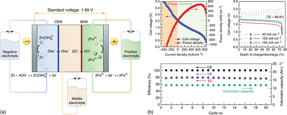
Figure 9 (a) Schematic of the Zn–Fe RFB; (b) power density, rate dependent and cycling performance of the demonstrated Zn–Fe RFB.
[Reproduced with permission from Ref. (68). © 2011 Elsevier]
Owing to the issue of iron cation hydrolysis at pH neutral condition, a few studies have investigated pH neutral Zn–Fe RFBs. The first neutral Zn–Fe system was reported by Li et al.(66) Glycine was applied as ligand reagent to complex free iron cation thus not only alleviate iron hydrolysis but also improve the redox kinetic of Fe3+/Fe2+ couples. A piece of polybenzimidazole (PBI) porous membrane was employed as a separator which reduced active materials crossover. The resulted RFB displayed a CE of 97.75%, and an EE of 86.66% which was stable for 100 cycles. However, fast capacity (energy density) decay was observed during the cycling, which might come from iron complexes crossover and chemical decomposition. For this particular system, future work should focus on ligand design for iron cation stabilization and more ion‐selective membranes for better active materials retention.
4.3 Zn–Ce Redox Flow Batteries
Zinc–cerium (Zn–Ce) RFBs were first developed by Plurion Inc. (UK) in 2004 with a 2 KW system installed.(67) The Zn–Ce system displays the highest cell voltage of 2.43 V among all aqueous RFBs due to the very positive redox potential (1.28–1.72 V vs SHE) of Ce4+/Ce3+ pair. In this battery, Ce(CH3SO3)3 and Zn(CH3SO3)2 were employed as cathode and anode active materials, respectively.(49) A piece of Nafion membrane was applied as the separator. Different from vanadium base sulfate compounds which display good solubility in sulfuric acid, the Ce3+ active species are much less soluble (0.3 M) in the presence of sulfate. Methanesulfonic acid was found to be the best supporting electrolyte which enables good solubility of Ce species. High acid strength facilitates the solubility of Ce4+ active species. However, the solubility of Ce3+ decreases at higher acid concentrations which results in the highest operation concentration for Ce3+ active material of less than 1 M (Figure 10).(68)

Figure 10 Solubility of Ce3+ and Ce4+ species in H2SO4 and CH3SO3H supporting electrolytes with different concentrations.
[Reprinted with permission from Gong, K.; Xu, F.; Grunewald, J. B.; Ma, X.; Zhao, Y.; Gu, S.; Yan, Y., All‐Soluble All‐Iron Aqueous Redox‐Flow Battery. ACS Energy Lett. 2016, 1 (1), 89–93. © 2016 American Chemical Society]
In the last 15 years, a number studies have been conducted to investigate the chemical stability, solubility, and battery charging/discharging overpotential of Zn–Ce RFBs.(52,69) Lots of efforts have also been made to protect zinc anode and improve the CE.(70) Based on the intrinsic chemistry and configuration, and the research progress of the Zn–Ce RFBs, several main challenges for Zn–Ce RFBs are summarized as follows: (i) relatively low energy density (25–35 Wh L−1) due to the low solubility of active materials;(68) (ii) the poor redox kinetics of Ce4+/Ce3+ pair;(68) (iii) low CE due to Zn corrosion in the strong acid electrolyte and active materials crossover;(70) and (iv) water splitting side reaction because of the high operation potential window.(49)
4.4 Zn–Organic Redox Flow Batteries
In addition to Zn–inorganic RFBs, zinc–organic hybrid aqueous systems have also been drawing many attentions recently. Comparing to inorganic redox‐active materials, organic molecules have displayed several advantages for RFB application, such as great elemental abundance and potential low costs, excellent redox kinetics, and tunable properties (solubility, charge state, and redox potential). Several zinc–organic hybrid systems, based on zinc/TEMPO and zinc/polymer, have been developed and demonstrated to be promising for highly energy dense and low‐cost energy storage.(50,51)
5 All‐iron Redox Flow Battery
The redox chemistry of all‐iron RFBs is based on the Fe3+/Fe2+ redox couple at the cathode and the Fe2+/Fe0 couple at the anode (Equations 212223),(71) which are semi‐flow flow batteries similar as Zn‐based RFBs. During the discharging process, Fe3+ is reduced to Fe2+ in the cathode side while metallic Fe is dissolved into the electrolyte and oxidized into Fe2+. The processes are reversed during battery charging.
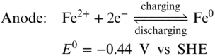
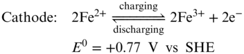
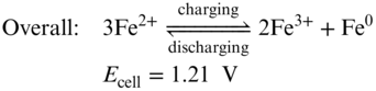
Using the inexpensive and highly soluble FeCl2 as the bipolar active materials for both cathode and anode, an aqueous all‐iron redox flow rechargeable battery can deliver cell voltage of 1.21 V and theoretical energy density of 76 Wh L−1 which stands for a promising, low‐cost, durable, and eco‐friendly energy storage system for large‐scale applications. The very first all‐iron RFB was reported by Hruska and Savinell in 1981.(71) Although it has been studied for almost 30 years, the all‐iron RFB is still limited to lab research level due to several challenges such as low CE, low EE, and poor cycling stability. The sacrificed CE is mainly due to the hydrogen evolution and Fe3+ crossover.(4) There is an intrinsic conflict between suppressing HER side reaction and hindering the iron cation hydrolysis in all‐iron RFBs. The pH values of catholyte and anolyte are kept around 1 and 4, respectively. At this condition, HER competition in anode side could be thermodynamically favorable. Moreover, during charging process of the battery, the electro‐deposition of iron presents substantial overpotential thereby facilitating the HER further. All‐iron RFBs use Nafion membranes to minimize the resistance of the whole battery. In this circumstance, maintaining the pH difference is difficult. Once the acidity decreases in the anode side, precipitation of iron hydroxide would occur.(72) Meanwhile, Fe3+ could cross through the membrane and react with Fe0 which causes serious self‐discharge. Efforts has been made to preserve the pH difference and minimize the Fe species crossover by employing AEMs.(72) However, the high resistance of the membrane resulted in a low EE (50%) and a low power density (50 mW cm−2). The low EE of the all‐iron RFBs is mainly owing to poor redox reaction kinetics of iron deposition/stripping process and low ion conductivity of the electrolyte.
To suppress iron cation hydrolysis and improve Fe3+/Fe2+ redox couple kinetics, a series of organic ligands were evaluated such as citrate, dimethyl sulfoxide (DMSO), glycerol, glycine, malic acid, malonic acid, and xylitol.(73) Among the studied ligands, glycine turned out to be the best for improving the reversibility of Fe3+/Fe2+ couple redox reaction. It was reported that a stable Fe cathode electrolyte (1:1 glycine to iron, pH = 2) displayed a solubility of 0.5 M and a redox potential of 0.690 versus SHE, suitable for the use as a positive redox couple in the all‐iron flow battery. This ligand stabilized Fe electrolyte was also applied in Zn–Fe RFBs, which we introduced above. Glycine as a ligand shows a weak electronic effect to the iron metal center, as the ![]() /
/![]() couple shows a very close redox potential with free Fe2+/Fe3+. However, other ligands can play an important role of tuning Fe‐ligand complexes' redox potential as shown in Figure 11.
couple shows a very close redox potential with free Fe2+/Fe3+. However, other ligands can play an important role of tuning Fe‐ligand complexes' redox potential as shown in Figure 11.

Figure 11 Redox pairs of iron complexes that have been tested for RFB applications.
[Reprinted with permission from Gong, K.; Xu, F.; Grunewald, J. B.; Ma, X.; Zhao, Y.; Gu, S.; Yan, Y., All‐Soluble All‐Iron Aqueous Redox‐Flow Battery. ACS Energy Lett. 2016, 1 (1), 89–93. © 2016 American Chemical Society]
Noteworthy, when triethanolamine (TEA) acts as the ligand, the resulted [Fe(TEA)OH]−/[Fe(TEA)OH]2− couple shows a redox potential as low as −0.86 V versus SHE in alkaline solution (Figure 10), which is very attractive for high‐voltage RFBs. The redox reaction is highly reversible which indicates excellent kinetics. The properties of the Fe–TEA complexes were first studied by Yang et al.(74) With an increase of the concentration of TEA, the solubility of Fe(III)–TEA can be increased to 0.6 M, and the solubility of Fe(II)–TEA is up to 0.4 M. Pairing the Fe(II)–TEA electrolyte (in 1 M NaOH) solution with neutral NaBr electrolyte, the resulted Fe–TEA/Br2 RFB delivered a high OCV up to 2 V. Owing to the high viscosity of the anolyte, relatively low current density (20 mA cm−2) was applied to charge and discharge the battery. An EE of 70% was obtained. However, long‐term cycling stability is poor due to the active material (Br2) crossover and pH change of the electrolyte. In addition, there was no post‐cell analysis to verify stability of the Fe–TEA complexes.
Following Yang and coworkers' study,(74) Gong et al.(75) demonstrated an all soluble all iron alkaline RFB based on an Fe(II)–TEA anolyte and an K4Fe(CN)6 catholyte. The reported all‐iron RFB showed a cell voltage of 1.34 V and could deliver a power density of 160 mW cm−2. With the solubility limit of the Fe–TEA complex, the RFB long‐term cycling was conducted at the concentration of 0.2 M at 40 mA cm−2, which indicated a low energy density of less than 3 Wh L−1. A low CE of 80–90% was obtained, which was due to ligand dissociation and free TEA crossover (Figure 12).

Figure 12 (a) Cyclic voltammograms of K2Fe(CN)6 and Fe–TEA in NaOH solution; (b) power density of the all‐iron RFB; (c) cycling performance of the all‐iron RFB.
[Reproduced with permission from Ref. (85). © Wiley VCH 2016]
Along with aqueous all‐iron RFBs, concepts for nonaqueous all‐iron RFBs were also reported in ionic liquids.(76,77) In the nonaqueous condition, HER side reaction and Fe(OH)X formation could be overcome. Ionic liquids were prepared by mixing FeClX, choline chloride, and ethylene glycol and used as electrolyte. The ionic liquids have acceptable intrinsic conductivities (without the need for added supporting electrolyte), high concentrations of iron (up to 6.3 M), large voltage windows, and enhanced safety due to the inert nature of the precursor materials as well as their low volatility. However, no battery cycling data was reported.
6 Polyoxometalate and Heteropolyacid Redox Flow Battery
A polyoxometalate (POM) is an oxoanion containing more than one metal atom formed by the linkage of d 0 metal‐centered polyhedral with oxygen atoms located at the vertices. The versatility and accessibility of POMs have led to many applications such as catalysis, luminescence, electronic conductors, and potential medicinal applications.(78) In addition, a POM has the capability to undergo reversible multi‐electron redox processes due to multiple redox‐active centers.(79) This desired property is very attractive for energy storage application because of the chance to largely improve energy density (Equation 3). In the recent years, POMs have been widely applied in lithium ion batteries, supercapacitors, and other electrochemical devices.(80)
Besides the merits of POMs mentioned above, POMs are easy to synthesize, stable, and soluble in water or organic solvents.(81) These advantages make POMs promising candidates for RFB applications, especially for using them as bipolar active materials (the same material for both cathode and anode) in a RFB, which overcomes the CE loss and capacity decay resulted from active materials crossover. Pratt et al. reported a series of bipolar electrolytes that contain POMs such as [SiV3W9O40]10−, [PV3W9O40]9−, and [(SiFe3W9(OH)3O34)2(OH)3]14−.(82–84) The RFBs based on these POMs displayed low cell voltages from 0.4 to 0.6 V due to the small redox potential difference between two redox events. Very low energy density (less than 1 Wh L−1) was demonstrated because of the low concentrations of active materials. Owing to the poor redox reaction kinetics, all the three POM‐based RFBs showed poor power densities and energy efficiencies (lower than 50%) even though strong acids were used as supporting electrolytes. In 2016, Yan and coworkers developed an acid form of POM material, H6CoW12O40 (Tungsten–Cobalt Heteropolyacid), as a bipolar active material for an acidic aqueous RFB.(85) This heteropolyacid can undergo five electron redox processes including two two‐electron redox reactions (for a total of four electrons) used the anode side, and a one‐electron redox reaction used as the cathode side, giving a cell voltage of 1.2–1.4 V, as shown in Figure 13 and electrochemical reactions.
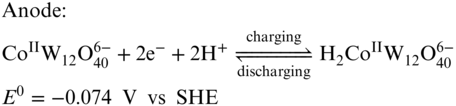
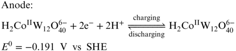
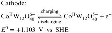

Figure 13 (a) Cyclic voltammograms of H6CoW12O40; (b) representative charge/discharge curve for the battery; (c) efficiency performance of the demonstrated RFB at various current density; (d) cycling performance of the RFB.
[Reproduced with permission from Ref. (105). © Cell Press 2017]
Along with a solubility of 1.0 M in water at room temperature, H6CoW12O40 is very suitable for RFB application. As the [CoW12O40]6− anion is highly negatively charged and has a very large size, Nafion separator can effectively avoid the active materials crossover, which ensure a high CE. When one H6CoW12O40 molecule is dissolved in water, it dissociates to give the redox‐active anion and 6 protons which can be used as the charge shuttle. Therefore, no supporting electrolyte was required for this system. The all‐H6[CoW12O40] RFB exhibited a high energy density of 86% with a GF electrode at a current density of 25 mA cm−2 with a volumetric specific energy of 15.4 Wh L−1. An extended cycling study was tested for only 30 cycles at 25 mA cm−2 displaying a good capacity retention. The follow‐up work for the H6CoW12O40 RFB by the same group studied the effect of Nafion membrane thickness on performance of the battery.(86) By replacing Nafion 212 to Nafion 211 membrane, both EE and power density were improved dramatically, while CE was sacrificed. The obtained highest power density of this system was 0.56 W cm−2, which represents one of the most powerful aqueous RFBs. It is important to note that, in order to perform best capacity utilization, the volume ratio between the catholyte and the anolyte was tuned to be 4:1 according to the amount of electrons involving in the anode and cathode reactions.
Stimming et al. reported two POMs that could be used as active materials for an asymmetric aqueous RFB.(87) Based on the trend that the redox potential decreases with the increasing electronegativity (χ) of POM species, [SiW12O40]4− (SiW12, χW = 2.36) and [PV14O42]9− (PV14, χV = 1.63) were selected as anode materials and cathode materials, respectively. An in situ NMR test during an electrochemical experiment revealed excellent chemical and electrochemical stability of PV14. Both SiW12 and PV14 can undergo multi‐electron process. PV14 can be reduced by as many as seven electrons, whereas during battery operation the molecule was reduced by only four electrons. SiW12 can be reduced by four electrons. With concentrations of 0.1 M for PV14 and 0.2 M for SiW12, the RFB had a theoretical capacity of 10.7 Ah L−1 and was able to reach this value during actual battery operation. Capacity decay was clearly observed in 155 cycles and verified to be due to the ingress of atmospheric oxygen instead of the instability of the redox‐active POMs. However, the 4 out of 7 electron utilization limitation of the PV14 POM still needs to be further explored and elucidated.
Very recently, Cronin and coworkers reported a polyanion, [P2W18O62]6−, which displays notable proton‐coupled electron redox activity and can undergo a series of total 18‐electron redox processes.(88) Interestingly, with the increase of concentration of this POM materials, the amount of charge in terms of protons and electrons that can be reversibly stored also increased (4 electrons at the concentration of 2 mM, 16 electrons at 50 mM, and ca.17.2 electrons at 100 mM). Another salient feature is the high solubility [P2W18O62]6− POM in water. The Li+ counter cation‐based POM displays a solubility of 1.9 M, which indicates a theoretical capacity of more than 900 Ah L−1. When paired with Br2, the resulted RFB gives an extremely high theoretical energy density up to 1000 Wh L−1, three times of Zn–I2 RFB. The demonstrated 1.25 V POM–Br2 RFB with a POM concentration of 0.5 M in acidic electrolytes delivered an energy density of 225 Wh L−1, a power density of 0.5 W cm−2 and stable capacity retention for 20 cycles. However, the chemical stability and long‐term cycling stability of POM molecules need to be further studied. In addition, the deeply reduced materials can also react with protons to generate hydrogen even at pH neutral condition in the absence of Pt/C catalyst. Therefore, the inevitable HER side reaction could jeopardize the long‐term stability of [P2W18O62]6− based acidic flow battery.
7 Polysulfide–Polyhalide Redox Flow Batteries
Polysulfide has been recognized as a promising candidates as anolyte materials of a RFB due to its high abundance, low cost, and good solubility in aqueous media.(67) Polysulfide–polyhalide RFBs received the most attention and commercialization has been reported up to a 1 MW system. Polysulfide–bromine RFB system is developed by Regenesys Ltd.(89) For a polysulfide–bromine redox flow battery (SBRFB), during the charging cycle, the bromide is oxidized to bromine and complexed as tribromide ions in the cathode side. In the anode side, the sulfur present as soluble polysulfide anion is reduced as shown in Equations 27–29.(67) Normally, sodium or potassium cations are applied as charge carriers, thus cation exchange membrane is required for the SBRFB systems.


The SBRFB suffers from the same cathode issues as other bromine base systems, such as Zn–Br2 RFB discussed above. Besides, the poor kinetics of ![]() /
/![]() redox reaction also restrains the EE of the flow battery. Therefore, catalysts are essential for the polysulfide anode to improve battery performance. In recent years, metal sulfide‐based catalysts have been studied to facilitate the polysulfide redox reaction.(90) For example, Yi and coworkers first employed nickel foam pretreated with Na2S4 solution as an electrocatalytic anode current collector in a SBRFB. EE was obtained as high as 77.2% at a current density of 40 mA cm−1, which attributes to the generated NiSX catalyst on the surface of Ni foam.(90)
redox reaction also restrains the EE of the flow battery. Therefore, catalysts are essential for the polysulfide anode to improve battery performance. In recent years, metal sulfide‐based catalysts have been studied to facilitate the polysulfide redox reaction.(90) For example, Yi and coworkers first employed nickel foam pretreated with Na2S4 solution as an electrocatalytic anode current collector in a SBRFB. EE was obtained as high as 77.2% at a current density of 40 mA cm−1, which attributes to the generated NiSX catalyst on the surface of Ni foam.(90)
As an analog of the SBRFB system, polysulfide–iodine redox flow batteries (SIRFBs) also stand for a cost‐effective system that are promising to meet the $150 per kWh price target set by DOE. SIRFBs have been drawing increasing attention than SBRFB for fundamental studies due to much better solubility and redox kinetics of I−/I3− species than Br−/Br3−. Without any catalyst, CV shows that I−/I3− redox pair displays much smaller peak–peak separation (240 mV) than Br−/Br3− (730 mV) at the scan rate of 100 mV s−1 at a carbon electrode.(9) Lu et al. reported a high‐energy and low‐cost SIRFB using nickel foam as anode electrode to facilitate ![]() /
/![]() redox reaction.(9) 3.3 M K2S2 in 1 M KOH and 6 M KI aqueous solution were employed as an anolyte and an catholyte, respectively. This combination gives a cell voltage of 1.05 V, which is lower than SBRFB because of the relatively lower redox potential of I−/I3− redox couples than Br−/
redox reaction.(9) 3.3 M K2S2 in 1 M KOH and 6 M KI aqueous solution were employed as an anolyte and an catholyte, respectively. This combination gives a cell voltage of 1.05 V, which is lower than SBRFB because of the relatively lower redox potential of I−/I3− redox couples than Br−/![]() . With a high concentration of active materials, the achieved energy density reaches 43.1 Wh L−1. However, the high viscosity and low conductivity of the concentrated electrolyte resulted in low EE, only 55% at the current density of 20 mA cm−2. In 2017, Brushett group also demonstrated a SIRFB using Na+ as the charge shuttle.(91) The battery gives consistent cycling performance for more than 200 cycles. However, the EE is still not satisfactory. In addition, it is worth noting that polysulfides are not chemically stable under alkaline conditions,(92) meaning they should be used at pH neutral conditions for more stable cycling performance.
. With a high concentration of active materials, the achieved energy density reaches 43.1 Wh L−1. However, the high viscosity and low conductivity of the concentrated electrolyte resulted in low EE, only 55% at the current density of 20 mA cm−2. In 2017, Brushett group also demonstrated a SIRFB using Na+ as the charge shuttle.(91) The battery gives consistent cycling performance for more than 200 cycles. However, the EE is still not satisfactory. In addition, it is worth noting that polysulfides are not chemically stable under alkaline conditions,(92) meaning they should be used at pH neutral conditions for more stable cycling performance.
Besides the above‐discussed RFBs, other inorganic‐based aqueous RFBs have also been developed, such as hydrogen–halogen RFBs, soluble lead RFBs, and copper RFBs.(4) However, they are less attractive because of different technological limitations and will not be discussed here.
8 Other Nonaqueous Inorganic Redox Flow Batteries
8.1 Lithium‐Based Semi‐Flow Redox Flow Batteries
Several lithium‐based semi‐flow RFBs have been reported using lithium metal as anode paired with polysulfide, iodide, and organic materials cathode materials.(93–96) Cui et al. first demonstrated the concept of a membrane‐free Li/polysulfide hybrid battery with a theoretical energy density of 105 Wh L−1.(93) However, the battery test under real flow condition was not conducted. An aqueous/nonaqueous hybrid Li/I2 RFB was reported Byon and coworkers.(94) The LiI aqueous cathode served as a highly soluble and stable I−/I3− redox couple in the RFB, providing high energy and power densities (up to 130 mW cm−2). 1 M LiPF6 in ethylene carbonate (EC)/dimethyl carbonate (DMC) was used as anolyte. Solid electrolyte (LAPT) was applied as the separator to allow the Li ion conducting and avoid the crossover of any other materials and solvent. The addition of the flow device and aqueous electrolyte reservoir resulted in a further increase in capacity up to 90% of the theoretical capacity. The demonstrated Li/I2 RFB displayed a total 100 mAh of battery performance without significant capacity loss and potential degradation in 20 cycles.
Although high energy density can be achieved with these systems, they sacrifice the capability of decoupling power and energy of a RFB. In order to keep both advantages, a solid‐suspension approach was proposed using Li‐intercalation materials as cathode materials which are suspended in solvent phase homogeneously.(97) As most of the solid active materials are insulated, conductive additives are required to improve the ionic conductivity of the slurry electrolyte. Duduta et al.(97) first applied this concept using LiCoO2 slurry (20 vol%, 10.2 M and 1.5% ketjenblack) and Li4Ti5O12 (10 vol%, 2.3 M and 2% ketjenblack) slurry as cathode and anode, respectively. The following study on silicon anode material, polysulfide, LiTi(PO4)3, LiFePO4, and other material using similar methods were also conducted. The solid‐suspension electrolyte‐based RFBs can achieve a high theoretical energy density. For example, Duduta et al.(97) estimated a high energy density up to 397 Wh L−1 for the LiCoO2–Li4Ti5O12 if the volume loading is as high as 40%. However, the low conductivity and high viscosity of the electrolyte result in low capacity utilization of these RFBs. Meanwhile, the low volume ratio (normally 20 vol%) of active material also limits further improvement of batteries' energy density.(98)
This issue could be overcome with a redox targeting approach which was first proposed by Wang et al.(99) The main idea of the redox targeting is to apply soluble redox‐active molecules to shuttle electrons between insoluble active materials and electrodes, which allows the insoluble active materials to be oxidized/reduced without using a significant amount of conductive additives. Different from a typical RFB, in redox targeting RFBs, electron mediator solution flows through the cell while solid active materials such as LiFePO4 are maintained statically in the anode and cathode reservoirs.(98) Using this strategy, several systems reported by Wang et al. have been demonstrated with very high energy density and active materials utilization.(100–104) In these RFBs, the redox potentials of redox mediators are required to match those of the solid active materials. This prerequisite requires the careful selection of redox targeting molecules. In the first reported redox targeting RFBs, two redox mediators with a single redox event(101,104) or one redox mediator with two redox events(102,103) were used to bracket the redox potential of solid active materials, in which the lower potential process reduces the solid material for lithiation and the higher potential process oxidizes the solid material for delithiation. These two redox systems, however, inevitably induces voltage loss to the system as a result of the relatively large potential difference between the two redox events. More recently, the team reported a single redox mediator‐based LiFePO4/Li redox targeting RFB (Figure 14).(105) In this redox targeting RFB, an imidazolium functionalized ferrocene (FcIL, Figure 14a) was ingeniously selected as a single redox mediator. Because of its perfect redox matching with LiFeO4 (Figure 14b), the ferrocene redox mediator through its single redox event at 3.42 V versus Li could promote Nernstian redox‐driven reversible charge/discharge of the solid LiFePO4 cathode material at 0.025 mA cm−2 with a demonstrated energy density of 330 Wh L−1. The FcIL single redox mediator‐based redox targeting RFB clearly outperforms previously reported redox targeting RFBs in terms of VE and capacity utilization of solid cathode materials.

Figure 14 (a) Molecular structure of FcIL. (b) Cyclic voltammograms of 50 mM FcIL on a double‐layer electrode in the absence (orange) and presence (green) of FePO4/LiFePO4 (1:1). For comparison, the gray curve shows the CV of a FePO4/LiFePO4‐coated double‐layer electrode in the absence of FcIL in the electrolyte. The electrolyte was 1MLiTFSI/PC. The scan rate was 2 mV s−1. The insets illustrate the reaction of FcIL on the double‐layer electrode. (c) Voltage profiles of flow cells with 0.20 M FcIL in the catholyte and 0.37 M equivalent LiFePO4 granules in the tank. The inset is the enlarged voltage profiles of the flow cells after IR correction. The electrolyte was 1 M LiTFSI/PC. The current density was 0.025 mA cm−2.
[Reproduced with permission from Ref. (108). © Cell Press 2018]
In addition, redox targeting RFBs need to operate at a low current density (<1 mA cm−2) to ensure effective redox mediating process to achieve the high charge capacities of solid active materials. In this regard, it is believed that redox targeting RFBs have potential to meet long‐duration energy storage needs (hours to days) where power performance is not critically important. Moreover, the redox targeting RFBs also suffers from low CE due to the lack of effective separators in organic solvent which is needed to selectively mitigate the crossover of redox mediators. To overcome the separator issue while achieving higher current and power performance, it appears reasonable to develop redox targeting RFBs using well‐developed ion exchange membranes in aqueous environment.
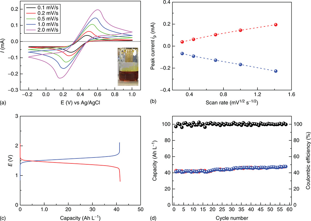
Figure 15 (a) CV curves of Fe(126) DES at different sweeping rates. (b) Linear relationships between the oxidation and reduction peak current with the square root of the sweeping rate. (c) Charge/discharge profile of Fe(126)–DES/EC–DMC (1.7 M, 0.05 mL) paired with Al–DES/DCE (3.2 M, 0.1 mL) at current density of 0.1 mA cm−2. (d) The charge and discharge capacity with corresponding coulombic efficiency of an Fe(126)–Al battery at room temperature over cycling.
[Reproduced with permission from Ref. (107). © Cell Press 2017]
8.2 Deep‐Eutectic‐Solution‐Based Inorganic RFBs
Deep eutectic solution (DES) is a mixture of electroactive metal salts, solvation additives, and organic solvent with unique physical properties, such as low melting points and high conductivities, and has been recognized as a distinct class of low‐cost catholytes or anolytes that potentially have high concentration of electroactive species for RFB applications. The first concept of proof demonstration of DES redox‐active electrolytes was reported by Zhou et al. in an Fe–DES/Li RFB.(106) The deep brown Fe‐based DESs were simply prepared by mixing FeCl3·6H2O and urea and achieved a concentration of 5.4 M for FeCl3 (a charge capacity of 144.72 Ah L−1) with a freezing point at about −7.1 °C. Such Fe–DES is attractive cathode‐active materials because of their stability, high earth abundance, and high redox potential (Fe3+/2+ at 0.77 V vs NHE or 3.4 V vs Li). At 40 °C, 97% capacity of the Fe–DES was achieved in a Li semi‐flow battery, corresponding to an exceptionally high energy density of ca. 480 Wh L−1. Subsequently, Yu et al. developed a low‐cost Al–DES anolyte (2.2 V vs Li) to demonstrate a semi‐flow battery with I3−/I− and Br3−/Br− with a high energy density of up to 200 Wh L−1.(107) More recently, Yu group combined a new Fe(126)–DES catholyte (where 126 stands for the 1:2:6 ratio of FeCl3·6H2O/urea/ethylene glycol) and the Al–DES anolyte to demonstrate a 1.4 V full DES RFB with a demonstrated energy density of 58.1 Wh L−1 (Figure 14).(108) In spite of a low energy density compared to the reported DES/Li RFBs, the Fe–DES/Al–DES RFB delivered an impressive cycling stability for ca. 1500 h at 0.1 mA cm−2 (Figure 14d). Low current performance (1 mA cm−2) and low power densities (<5 mW cm−2) of the reported DES RFBs are largely due to the use of a solid electrolyte separator with a low ion conductivity which is necessary to avoid the crossover of active materials. Thus, similar as redox targeting RFBs, DES RFBs with their high energy densities are more suitable for long duration energy storage applications (hours to days). In addition, it is important to develop a cost model for DES RFBs regarding their capital costs by considering both low‐cost DES electrolytes and expensive solid electrolyte separator (Figure 15).
8.3 Polyoxometalate‐Based Nonaqueous Inorganic RFBs
Not limited to aqueous systems, POMs‐based nonaqueous RFBs have also been developed. To meet the requirement of nonaqueous RFB application, Matson et al. developed a series of POMs based on Ti and V metal elements and applied them as bipolar active materials.(109,110) Alkyl oxide groups, −OR (R represents for methyl or ethyl group), were introduced to improve the cluster's solubility in organic solvents. The designed [V6O7(OR)12] nonaqueous RFB showed a cell voltage of 1.6 V. The incorporation of one ([TiV5(OCH3)13]) or two ([Ti2V4(OCH3)14]) titanium ions within the Lindqvist core ([V6O7(OR)12]) significantly increases the cell voltage of the system (from 1.60 V, to 2.30 and 2.74 V, respectively) while the solubility and redox stability observed for cluster complexes is retained.
9 Perspective
Over the past several decades, aqueous inorganic RFBs based on various chemistries have been proposed and developed in both academic institutions and industries. However, these systems are still facing several representative challenges regarding chemical stability of active materials, side reactions, and electrolyte crossover, which impede the cycling stability and efficiency of inorganic RFBs. Herein, we would like to point out considerations and possible solutions to address these issues.
- Chemical stability. Metal salt‐based RFBs are facing a problem of metal hydroxide or metal oxide formation under pH neutral or alkaline conditions, which substantially affects battery stability and efficiency (due to the increase of battery resistance). For nonmetal redox‐active species, such as polysulfide and iodide, pH neutral condition is crucial as they are unstable under acidic or alkaline conditions as discussed above. The chemical nature of redox‐active inorganic compounds leaves very limited space for structural modulation to improve their chemical stability as well as other physicochemical properties. When combining different inorganic redox couples to form a flow battery, one needs to carefully consider the best pH condition under which both anolyte and catholyte can be chemically stable in their charged and discharged states. A viable option is to use a suitable organic anolyte or catholyte to replace an unsuitable inorganic one to construct a hybrid inorganic/organic RFB, which can largely increase the design space to meet the chemical stability requirement.(15,111,112)
- Side reactions. Simple metal salt‐based RFBs usually need acidic electrolytes to prevent metal hydrolysis to form metal hydroxide precipitates or metal oxides. However, under acidic conditions, HER is thermodynamically favorable and competitive to occur if an anode active materials' redox potential is more negative than the HER potential or a flow battery is charged with an overpotential beyond the HER potential. HER may represent a major capacity decay mechanism for acidic RFBs. For example, the HER problem has been well documented for highly acidic all vanadium RFBs.(113,114) In addition to HER, water and supporting electrolyte anion oxidation (such as Cl−) could also happen in RFBs with a catholyte with a very positive redox potential (such as Ce3+/Ce4+). When choosing an anode or cathode material and electrolyte conditions, these sides reactions need to be carefully considered. A possible option is developing low cost and efficient electrocatalysts to facilitate the redox chemistry of active materials to avoid overpotential to trigger the side reactions. Alternatively, it is also possible to develop engineering solutions to convert side products such as hydrogen gas back to protons and electrons to remedy the charge imbalance between an anolyte and an catholyte, which may lead to the increase of the system capital cost.
- Active material crossover. Most of the redox inorganic compounds including metal salts or nonmetal salts typically have small solvation sphere sizes and can still crossover an ion exchange membrane leading to capacity decay. Again, due to their simple chemical structures, structural modification is not feasible to improve their membrane compatibility. Especially, the crossover issue is even more challenging for nonaqueous RFBs including both inorganic and organic RFBs. It means that we have to rely on the development of advanced membranes or separators to address this problem. As discussed above, it is possible to apply solid‐state electrolyte separators for inorganic RFBs to achieve good capacity retention.
In addition, we would like to advocate to use a half‐cell flow battery approach to evaluate the chemical stability and cycling performance of individual redox‐active inorganic compounds. In the half‐cell flow battery approach which adopts the same flow battery design as shown in Figure 1, both the charged state and discharged state of an individual redox‐active compound will be applied in each of their respective electrode sides. The half‐cell approach allows a systematic evaluation of the electrochemical performance of a single electrolyte material‐based electrolyte under actual full flow battery conditions while decoupling the complications from the performance of another electrolyte material, as occurs in a full flow battery. By monitoring CE and cycling stability of the half‐cell, this method can effectively diagnose side reactions and chemical decomposition through other spectroscopic tools such as NMR, UV–vis, and FTIR. This approach has been recently applied to elucidate the pH‐dependent cycling stability of ferrocyanide by us.(62) Aziz and co‐workers also applied this approach to determine the cycling stability of a number of individual redox‐active organic molecules.(115)
10 Conclusion
Owing to the salient features of RFBs, they have a promising future to be the one of the key elements in large‐scale grid‐integrated energy storage systems because they hold promise to offer long cycle life and high energy efficiencies as well as low operational costs. Over the past few decades, RFBs based on various chemistries have been proposed and developed for both fundamental studies and commercialization attempts. In this chapter, we summarized the most important inorganic materials that have been applied in RFBs and noticed that only a few systems have been applied for grid‐integrated energy storage with a scale from 1 MW to 15 MW. All‐vanadium, Fe/Cr, and Zn/Br2 systems share the same problem of hazardous and corrosive electrolytes, and they are not environmentally friendly electrochemical energy storage systems. To achieve a more advanced RFB system for sustainable, environmentally benign, low‐cost and reliable energy storage, challenges need to be addressed for increasing energy density, improving cycling stability, boosting EE, reducing the capital cost, and using less hazardous electrolyte materials.
11 Acknowledgments
We thank Utah State University for providing faculty startup funds to the PI (T. Leo Liu) and the Utah Science Technology and Research initiative (USTAR) UTAG award for supporting our flow battery project. Bo Hu is grateful to the China CSC Study Abroad program and Utah Energy Triangle Student Award for supporting his graduate program. Camden DeBruler is grateful for his USU Presidential Doctoral Research Fellowship (PDRF) supported by USU. Maowei Hu is grateful to the China CSC Study Abroad program for supporting her graduate program.
12 Abbreviations and Acronyms
AEM = anion exchange membrane;
CE = coulombic efficiency;
CV = cyclic voltammetry;
DES = deep eutectic solution;
DOE = U.S. Department of Energy;
DMC = dimethyl carbonate;
DMSO = dimethyl sulfoxide;
EC = ethylene carbonate;
EE = energy efficiency;
FESEM = field emission scanning electron microscope;
GF = graphite felt;
HER = hydrogen evolution reaction;
HRTEM = high‐resolution transmission electron microscopy;
ICRFB = iron–chromium redox flow battery;
NHE = normal hydrogen electrode;
NP = nanoparticle;
OCV = open circuit voltage;
PBI = polybenzimidazole;
POM = polyoxometalate;
RFB = redox flow battery;
SBRFB = polysulfide–bromine redox flow battery;
SHE = standard hydrogen electrode;
SHMP = sodium hexametaphosphate;
SIRFB = polysulfide–iodine redox flow battery;
STEM = scanning transmission electron microscopy;
SOC = state of charge;
TEA = triethanolamine;
TEMPO = (2,2,6,6‐tetramethylpiperidin‐1‐yl)oxyl;
VE = voltage efficiency;
VRFB = all‐vanadium redox flow battery.
References
- 1 https://www.esrl.noaa.gov/gmd/ccgg/trends/index.html, 2018.
- 2 B. Dunn, H. Kamath and J.‐M. Tarascon, Science, 2011, 334(6058), 928.
- 3 Z. Yang, J. Zhang, M. C. W. Kintner‐Meyer, X. Lu, D. Choi, J. P. Lemmon and J. Liu, Chem. Rev., 2011, 111(5), 3577.
- 4 G. L. Soloveichik, Chem. Rev., 2015, 115(20), 11533.
- 5 W. Wang, Q. Luo, B. Li, X. Wei, L. Li and Z. Yang, Adv. Funct. Mater., 2013, 23(8), 970.
- 6 J. Winsberg, T. Hagemann, T. Janoschka, M. D. Hager and U. S. Schubert, Angew. Chem. Int. Ed., 2017, 56(3), 686.
- 7 L. Li, S. Kim, W. Wang, M. Vijayakumar, Z. Nie, B. Chen, J. Zhang, G. Xia, J. Hu, G. Graff, J. Liu and Z. Yang, Adv. Energy Mater., 2011, 1(3), 394.
- 8 B. Li, Z. M. Nie, M. Vijayakumar, G. S. Li, J. Liu, V. Sprenkle and W. Wang, Nat. Commun., 2015, 6, 6303.
- 9 Z. J. Li, G. M. Weng, Q. L. Zou, G. T. Cong and Y. C. Lu, Nano Energy, 2016, 30, 283.
- 10 B. Hu, C. DeBruler, Z. Rhodes and T. L. Liu, J. Am. Chem. Soc., 2017, 139(3), 1207.
- 11 C. DeBruler, B. Hu, J. Moss, X. Liu, J. Luo, Y. Sun and T. L. Liu, Chemistry, 2017, 3(6), 961.
- 12 E. S. Beh, D. De Porcellinis, R. L. Gracia, K. T. Xia, R. G. Gordon and M. J. Aziz, ACS Energy Lett., 2017, 2(3), 639.
- 13 T. B. Liu, X. L. Wei, Z. M. Nie, V. Sprenkle and W. Wang, Adv. Energy Mater., 2016, 6(3), 1501449.
- 14 T. Janoschka, N. Martin, M. D. Hager and U. S. Schubert, Angew. Chem. Int. Ed., 2016, 55(46), 14425.
- 15 K. X. Lin, Q. Chen, M. R. Gerhardt, L. C. Tong, S. B. Kim, L. Eisenach, A. W. Valle, D. Hardee, R. G. Gordon, M. J. Aziz and M. P. Marshak, Science, 2015, 349(6255), 1529.
- 16 K. Lin, R. Gómez‐Bombarelli, E. S. Beh, L. Tong, Q. Chen, A. Valle, A. Aspuru‐Guzik, M. J. Aziz and R. G. Gordon, Nat. Energy, 2016, 1, 16102.
- 17 T. Janoschka, N. Martin, U. Martin, C. Friebe, S. Morgenstern, H. Hiller, M. D. Hager and U. S. Schubert, Nature, 2015, 527(7576), 78.
- 18 L.H. Thaller, ‘Electrically Rechargeable Redox Flow Cells’. NASA TM X‐71540, Lewis Research Centre, 1974.
- 19 W. Wang, S. Kim, B. Chen, Z. Nie, J. Zhang, G.‐G. Xia, L. Li and Z. Yang, Energy Environ. Sci., 2011, 4(10), 4068.
- 20 Y. K. Zeng, T. S. Zhao, L. An, X. L. Zhou and L. Wei, J. Power Sources, 2015, 300, 438.
- 21 C. D. Wu, D. A. Scherson, E. J. Calvo, E. B. Yeager and M. A. Reid, J. Electrochem. Soc., 1986, 133(10), 2109.
- 22 D. S. Cheng and E. Hollax, J. Electrochem. Soc., 1985, 132(2), 269.
- 23 M. Skyllas‐Kazacos and M. Kazacos, J. Power Sources, 2011, 196(20), 8822.
- 24 http://enervault.com/, 2018.
- 25 M. Skyllas‐Kazacos, L. Cao, M. Kazacos, N. Kausar and A. Mousa, ChemSusChem, 2016, 9(13), 1521.
- 26 DOE Global Energy Storage Database (2016) https://www.energystorageexchange.org/projects/2043.
- 27 https://electrek.co/2017/12/21/worlds‐largest‐battery‐200mw‐800mwh‐vanadium‐flow‐battery‐rongke‐power/, 2017.
- 28 C. Choi, S. Kim, R. Kim, Y. Choi, S. Kim, H.‐y. Jung, J. H. Yang and H.‐T. Kim, Renew. Sustain. Energy Rev., 2017, 69, 263.
- 29 M. Ulaganathan, V. Aravindan, Q. Yan, S. Madhavi, M. Skyllas‐Kazacos and T. M. Lim, Adv. Mater. Interfaces, 2016, 3(1), 1500309.
- 30 G. Oriji, Y. Katayama and T. Miura, Electrochim. Acta, 2004, 49(19), 3091.
- 31 F. Rahman and M. Skyllas‐Kazacos, J. Power Sources, 2009, 189(2), 1212.
- 32 S. Kim, M. Vijayakumar, W. Wang, J. Zhang, B. Chen, Z. Nie, F. Chen, J. Hu, L. Li and Z. Yang, PCCP, 2011, 13(40), 18186.
- 33 S. Roe, C. Menictas and M. Skyllas‐Kazacos, J. Electrochem. Soc., 2016, 163(1), A5023.
- 34 J. Zhang, L. Li, Z. Nie, B. Chen, M. Vijayakumar, S. Kim, W. Wang, B. Schwenzer, J. Liu and Z. Yang, J. Appl. Electrochem., 2011, 41(10), 1215.
- 35 B. Li, M. Gu, Z. Nie, Y. Shao, Q. Luo, X. Wei, X. Li, J. Xiao, C. Wang, V. Sprenkle and W. Wang, Nano Lett., 2013, 13(3), 1330.
- 36 J. Shen, S. Liu, Z. He and L. Shi, Electrochim. Acta, 2015, 151, 297.
- 37 B. Li, M. Gu, Z. Nie, X. Wei, C. Wang, V. Sprenkle and W. Wang, Nano Lett., 2014, 14(1), 158.
- 38 W. Li, J. Liu and C. Yan, Carbon, 2011, 49(11), 3463.
- 39 M. Zago and A. Casalegno, Electrochim. Acta, 2017, 248, 505.
- 40 F. Zhang, S. Huang, X. Wang, C. Jia, Y. Du and Q. Wang, Nano Energy, 2018, 52, 292.
- 41 M. Skyllas‐Kazacos, J. Power Sources, 2003, 124(1), 299.
- 42 B. Li, L. Li, W. Wang, Z. Nie, B. Chen, X. Wei, Q. Luo, Z. Yang and V. Sprenkle, J. Power Sources, 2013, 229, 1.
- 43 W. Wang, Z. Nie, B. Chen, F. Chen, Q. Luo, X. Wei, G.‐G. Xia, M. Skyllas‐Kazacos, L. Li and Z. Yang, Adv. Energy Mater., 2012, 2(4), 487.
- 44 U.S. Department of Energy Grid Energy Storage, 2013; http://energy.gov/oe/downloads/grid‐energy‐storage‐december‐2013.
- 45 2018, 2, 121, https://www.vanadiumprice.com/.
- 46 D. J. Eustace, J. Electrochem. Soc., 1980, 127(3), 528.
- 47 B. Li, Z. M. Nie, M. Vijayakumar, G. S. Li, J. Liu, V. Sprenkle and W. Wang, Nat. Commun., 2015, 6, p.ncomms7303.
- 48 F. R. McLarnon and E. J. Cairns, J. Electrochem. Soc., 1991, 138(2), 645.
- 49 F. C. Walsh, C. Ponce de Léon, L. Berlouis, G. Nikiforidis, L. F. Arenas‐Martínez, D. Hodgson and D. Hall, ChemPlusChem, 2015, 80(2), 288.
- 50 J. Winsberg, T. Janoschka, S. Morgenstern, T. Hagemann, S. Muench, G. Hauffman, J. F. Gohy, M. D. Hager and U. S. Schubert, Adv. Mater., 2016, 28(11), 2238.
- 51 J. Winsberg, C. Stolze, A. Schwenke, S. Muench, M. D. Hager and U. S. Schubert, ACS Energy Lett., 2017, 2(2), 411.
- 52 A. Khor, P. Leung, M. R. Mohamed, C. Flox, Q. Xu, L. An, R. G. A. Wills, J. R. Morante and A. A. Shah, Mater. Today Energy, 2018, 8, 80.
- 53 M. Skyllas‐Kazacos, M. H. Chakrabarti, S. A. Hajimolana, F. S. Mjalli and M. Saleem, J. Electrochem. Soc., 2011, 158(8), R55.
- 54 Q. Lai, H. Zhang, X. Li, L. Zhang and Y. Cheng, J. Power Sources, 2013, 235, 1.
- 55 J.‐D. Jeon, H. S. Yang, J. Shim, H. S. Kim and J. H. Yang, Electrochim. Acta, 2014, 127, 397.
- 56 G.‐M. Weng, Z. Li, G. Cong, Y. Zhou and Y.‐C. Lu, Energy Environ. Sci., 2017, 10, 735.
- 57 J. Zhang, G. Jiang, P. Xu, A. Ghorbani Kashkooli, M. Mousavi, A. Yu and Z. Chen, Energy Environ. Sci., 2018, 11(8), 2010.
- 58 W. D. McCulloch, M. Yu and Y. Wu, ACS Energy Lett., 2016, 1(3), 578.
- 59 C. Xie, H. Zhang, W. Xu, W. Wang and X. Li, Angew. Chem. Int. Ed., 2018, 57(35), 11171.
- 60 G.B. Adams, Patent US4180623A, 1979.
- 61 Z. Yuan, Y. Duan, T. Liu, H. Zhang and X. Li, iScience, 2018, 3, 40.
- 62 J. Luo, A. Sam, B. Hu, C. DeBruler, X. Wei, W. Wang and T. L. Liu, Nano Energy, 2017, 42, 215.
- 63 Z. Xie, Q. Su, A. Shi, B. Yang, B. Liu, J. Chen, X. Zhou, D. Cai and L. Yang, J. Energy Chem., 2016, 25(3), 495.
- 64 S. Selverston, R. F. Savinell and J. S. Wainright, J. Electrochem. Soc., 2017, 164(6), A1069.
- 65 K. Gong, X. Y. Ma, K. M. Conforti, K. J. Kuttler, J. B. Grunewald, K. L. Yeager, M. Z. Bazant, S. Gu and Y. S. Yan, Energy Environ. Sci., 2015, 8(10), 2941.
- 66 C. Xie, Y. Duan, W. Xu, H. Zhang and X. Li, Angew. Chem. Int. Ed., 2017, 56(47), 14953.
- 67 C. Ponce de León, A. Frías‐Ferrer, J. González‐García, D. A. Szánto and F. C. Walsh, J. Power Sources, 2006, 160(1), 716.
- 68 P. K. Leung, C. Ponce de León, C. T. J. Low and F. C. Walsh, Electrochim. Acta, 2011, 56(5), 2145.
- 69 P. K. Leung, C. Ponce‐de‐León, C. T. J. Low, A. A. Shah and F. C. Walsh, J. Power Sources, 2011, 196(11), 5174.
- 70 P. K. Leung, C. Ponce‐de‐León, F. J. Recio, P. Herrasti and F. C. Walsh, J. Appl. Electrochem, 2014, 44(9), 1025.
- 71 L. W. Hruska and R. F. Savinell, J. Electrochem. Soc., 1981, 128(1), 18.
- 72 A. K. Manohar, K. M. Kim, E. Plichta, M. Hendrickson, S. Rawlings and S. R. Narayanan, J. Electrochem. Soc., 2016, 163(1), A5118.
- 73 K. L. Hawthorne, J. S. Wainright and R. F. Savinell, J. Electrochem. Soc., 2014, 161(10), A1662.
- 74 Y. H. Wen, H. M. Zhang, P. Qian, H. T. Zhou, P. Zhao, B. L. Yi and Y. S. Yang, Electrochim. Acta, 2006, 51(18), 3769.
- 75 K. Gong, F. Xu, J. B. Grunewald, X. Ma, Y. Zhao, S. Gu and Y. Yan, ACS Energy Lett., 2016, 1(1), 89.
- 76 D. Lloyd, T. Vainikka, M. Ronkainen and K. Kontturi, Electrochim. Acta, 2013, 109, 843.
- 77 M. A. Miller, J. S. Wainright and R. F. Savinell, J. Electrochem. Soc., 2016, 163(3), A578.
- 78 D. E. Katsoulis, Chem. Rev., 1998, 98(1), 359.
- 79 M. T. Pope and A. Müller, Angew. Chem. Int. Ed. Engl., 1991, 30(1), 34.
- 80 Y. Ji, L. Huang, J. Hu, C. Streb and Y.‐F. Song, Energy Environ. Sci., 2015, 8(3), 776.
- 81 H. N. Miras, J. Yan, D.‐L. Long and L. Cronin, Chem. Soc. Rev., 2012, 41(22), 7403.
- 82 H. D. Pratt Iii and T. M. Anderson, Dalton Trans., 2013, 42(44), 15650.
- 83 H. D. Pratt, N. S. Hudak, X. Fang and T. M. Anderson, J. Power Sources, 2013, 236, 259.
- 84 H. D. Pratt, W. R. Pratt, X. Fang, N. S. Hudak and T. M. Anderson, Electrochim. Acta, 2014, 138, 210.
- 85 Y. Liu, S. Lu, H. Wang, C. Yang, X. Su and Y. Xiang, Adv. Energy Mater., 2016, 7(8), 1601224.
- 86 Y. Liu, H. Wang, Y. Xiang and S. Lu, J. Power Sources, 2018, 392, 260.
- 87 J. Friedl, M. V. Holland‐Cunz, F. Cording, F. L. Pfanschilling, C. Wills, W. McFarlane, B. Schricker, R. Fleck, H. Wolfschmidt and U. Stimming, Energy Environ. Sci, 2018, 11, 3010.
- 88 J.‐J. Chen, M. D. Symes and L. Cronin, Nat. Chem., 2018, 10, 1042.
- 89 B. R. Chalamala, T. Soundappan, G. R. Fisher, M. R. Anstey, V. V. Viswanathan and M. L. Perry, Proc. IEEE, 2014, 102(6), 976.
- 90 P. Zhao, H. Zhang, H. Zhou and B. Yi, Electrochim. Acta, 2005, 51(6), 1091.
- 91 L. Su, A. F. Badel, C. Cao, J. J. Hinricher and F. R. Brushett, Ind. Eng. Chem. Res., 2017, 56(35), 9783.
- 92 I. Filpponen, A. Guerra, A. Hai, L. A. Lucia and D. S. Argyropoulos, Ind. Eng. Chem. Res., 2006, 45(22), 7388.
- 93 Y. Yang, G. Zheng and Y. Cui, Energy Environ. Sci., 2013, 6(5), 1552.
- 94 Y. Zhao and H. R. Byon, Adv. Energy Mater., 2013, 3(12), 1630.
- 95 F. R. Brushett, J. T. Vaughey and A. N. Jansen, Adv. Energy Mater., 2012, 2(11), 1390.
- 96 H. Chen, Y. Zhou and Y.‐C. Lu, ACS Energy Lett., 2018, 3(8), 1991.
- 97 M. Duduta, B. Ho, V. C. Wood, P. Limthongkul, V. E. Brunini, W. C. Carter and Y.‐M. Chiang, Adv. Energy Mater., 2011, 1(4), 511.
- 98 F. Pan and Q. Wang, Molecules, 2015, 20(11), 19711.
- 99 Q. Wang, S. M. Zakeeruddin, D. Wang, I. Exnar and M. Grätzel, Angew. Chem. Int. Ed., 2006, 45(48), 8197.
- 100 Q. Huang, H. Li, M. Grätzel and Q. Wang, PCCP, 2013, 15(6), 1793.
- 101 F. Pan, J. Yang, Q. Huang, X. Wang, H. Huang and Q. Wang, Adv. Energy Mater., 2014, 4(15), 1400567.
- 102 Q. Huang, J. Yang, C. B. Ng, C. Jia and Q. Wang, Energy Environ. Sci., 2016, 9(3), 917.
- 103 Y. G. Zhu, Y. Du, C. Jia, M. Zhou, L. Fan, X. Wang and Q. Wang, JACS, 2017, 139(18), 6286.
- 104 F. Pan, Q. Huang, H. Huang and Q. Wang, Chem. Mater., 2016, 28(7), 2052.
- 105 M. Zhou, Q. Huang, T. N. Pham Truong, J. Ghilane, Y. G. Zhu, C. Jia, R. Yan, L. Fan, H. Randriamahazaka and Q. Wang, Chemistry, 2017, 3, 1036.
- 106 Y. Wang and H. Zhou, Energy Environ. Sci., 2016, 9(7), 2267.
- 107 C. Zhang, Y. Ding, L. Zhang, X. Wang, Y. Zhao, X. Zhang and G. Yu, Angew. Chem. Int. Ed., 2017, 56(26), 7454.
- 108 X. Zhou, F. Zhao, Y. Guo, Y. Zhang and G. Yu, Energy Environ. Sci., 2018, 11, 1985.
- 109 L. E. VanGelder, A. M. Kosswattaarachchi, P. L. Forrestel, T. R. Cook and E. M. Matson, Chem. Sci., 2018, 9(6), 1692.
- 110 L. E. VanGelder, J. Mater. Chem. A, 2018, 6(28), 13874.
- 111 C. DeBruler, B. Hu, J. Moss, J. Luo and T. L. Liu, ACS Energy Lett., 2018, 3, 663.
- 112 A. Hollas, X. Wei, V. Murugesan, Z. Nie, B. Li, D. Reed, J. Liu, V. Sprenkle and W. Wang, Nat. Energy, 2018, 3(6), 508.
- 113 A. A. Shah, H. Al‐Fetlawi and F. C. Walsh, Electrochim. Acta, 2010, 55(3), 1125.
- 114 C.‐N. Sun, F. M. Delnick, L. Baggetto, G. M. Veith and T. A. Zawodzinski, J. Power Sources, 2014, 248, 560.
- 115 M.‐A. Goulet and M. J. Aziz, J. Electrochem. Soc., 2018, 165(7), A1466.