We are now going to connect the relay module and the current sensor to the Arduino Yún board, connect the power cable that will power up the lamp, and finally connect everything to the power socket in the wall. This part is slightly more difficult than the hardware connections in Chapter 1, Building a Weather Station Connected to the Cloud, as it involves more steps and uses a higher voltage that requires you to take some precautions. So, please be careful and follow all the steps.
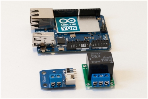
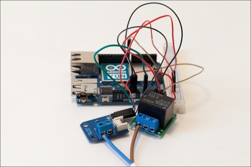
The first step is to put the Arduino Yún board, the relay module, and the current sensor board close to each other, as shown in the following image:
Then, we are going to connect the power supply of the relay module and the current sensor. As I said earlier in this chapter, the Arduino Yún board only has one 5V pin. This is why I connected the 5V pins of the two modules to a small piece of a breadboard first and then connected this breadboard to the Arduino 5V pin, as shown in the following image:
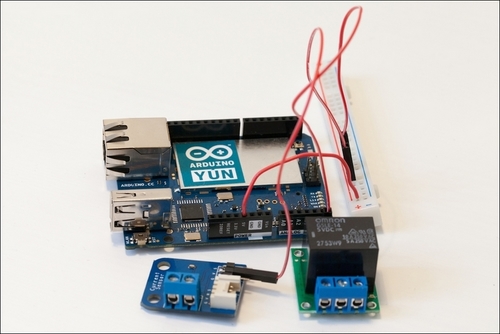
After this, we have to connect the ground pins of the two modules to the ground pin on the Arduino Yún board as shown in the following image. The Arduino Yún board has two ground pins on the board, so you don't have to use the breadboard for this.
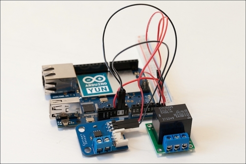
To finish with the connection of the two modules, we need to connect their respective signal pins to the Arduino board. The relay will be controlled via pin number 8 of the Arduino Yún board, so connect the signal pin of the relay module to pin number 8 of the Yún board.
The current sensor has an analog output, so it has to be connected to one analog input on the Arduino board in order to acquire the signal using one of the Yún integrated analog-to-digital converters. This converter will acquire the analog signal that comes from the sensor and transform it into digital values that range from 0 to 1023 (which correspond to a 10-bit precision). Connect the output pin of the current sensor module to pin number A0 of the Arduino Yún board, as shown in the following image:

That's basically all for the low-power part. Now, we will focus on connecting the project to the two power supply cables so that we can plug the project into the wall plug and plug the lamp to the project. We will start by connecting the cable that will go to the wall, as shown in the following image:
Finally, connect the female power plug that we will connect the lamp to, as shown in the following image:

Finally, it's time to power up everything. You can plug your Arduino Yún board in to your computer via a USB cable (if you want to upload sketches directly and want space for your computer to be around the project) or via a wall power socket to a USB adapter (if you plan to upload the sketches via Wi-Fi and leave the project to work on its own).
Then, plug the lamp or the device that you want to control in to the female power plug of the project. To finish, connect the male power plug to the power socket in the wall. Be careful while performing this step: make sure that no electrical conductors are exposed, all screw terminals are correctly screwed and are holding the cables firmly, and no bare electrical conductors touch each other.