
In the first two chapters, we set up UCSPE and looked at how to connect it physically, both to its own components and to the rest of the network. The physical cabling we looked at in the first chapter was, however, purely for management. This would allow us to control our UCS, but the blades and rack servers would have no connectivity to the rest of the network. In this chapter, we will be focusing on how to add the networking components that will let our UCS talk to the rest of the world.
UCS networking
At the moment, our UCS servers will be disconnected from the rest of the network, so we need to add means for them to pass packets to the rest of the network. We have a couple of ways to achieve this. We can use “Uplink” ports, or port-channels. We will start by looking at uplink ports.
Uplink ports
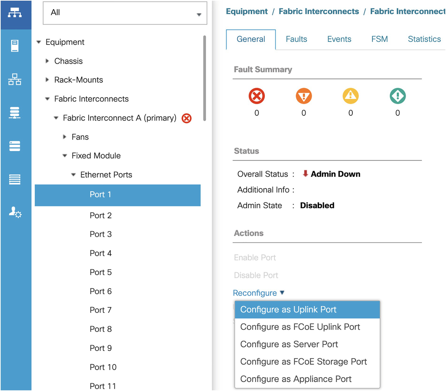
A screenshot of a reconfigure menu with port 1 option selected in the left panel and configure as uplink port selected in the right panel under the general tab.
Reconfiguring a port as an Uplink port
We will then need to confirm that we do wish to reconfigure the port, and then acknowledge the action once completed.

A screenshot of a dropdown menu with the option Eth interface one over one highlighted under all option.
Our Uplink interface

A screenshot of a window with a menu bar has tabs for general, faults, and events. The general tab is selected which has sections for properties and actions.
Uplink interface settings
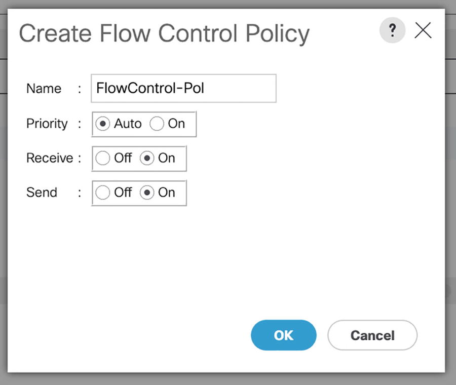
A dialog box titled create flow control policy has sections for name, priority, receive, and send with o k and cancel buttons on the bottom right.
Flow Control Policy

A screenshot of a window titled properties has sections for I D, slot I D, fabric I D, link profile, user label, transport type, flow control policy, and F E C.
Interface Flow control

A dialog box titled create U D L D link policy has sections for name, admin state, and mode with o k and cancel buttons on the bottom right.
UDLD modes

A dialog box titled create link profile has sections for name and U D L D link policy with o k and cancel buttons on the bottom right.
Link Profile
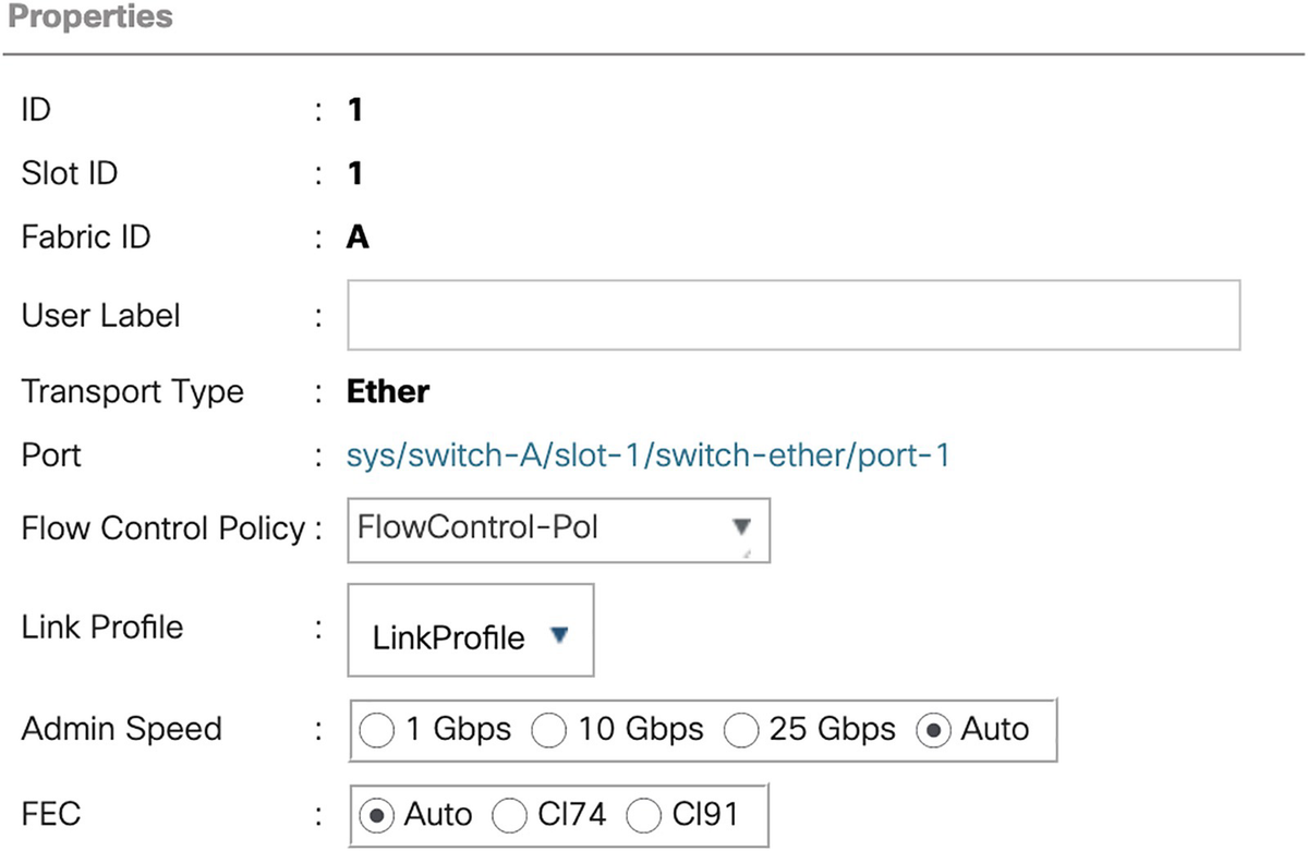
A screenshot of a window titled properties has sections for I D, slot I D, fabric I D, link profile, user label, transport type, port, and F E C.
Assigning a link profile to an interface
The following settings control the port speed and the Forwarding Equivalence Class (FEC), which is a form of quality of service.

A schematic of 4 connected channel segments in 2 columns for F I 1 and F I B.
FI redundant uplinks
While two interfaces are good, we are not making the best of our capabilities. With uplink ports, traffic is pinned to one of these links. One isn’t much fun when we could use all four cables at the same time (turning single 40GBps links into a combined 80GBps link).
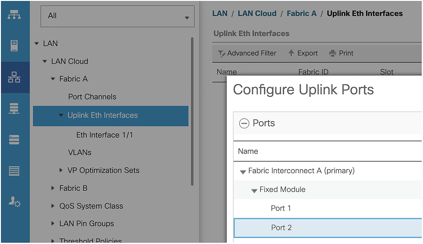
A screenshot of a dropdown menu titled configure uplink ports with port 2 option selected.
Adding another uplink
We also need to add two uplinks (eth1/1 and eth 1/2) to FI-B, using the same method.
Now we have an even number of links, we can create our port channels.

A dialog box titled create port channel has 2 options set port channel name and add ports with the first option highlighted.
Creating the port-channel

A dialog box titled create port channel has the selected option add ports with two sections on the screen for ports and ports in the port channel.
Adding interfaces to the port-channel

A dialog box titled create port channel has selected option add ports with two sections for ports and ports in the port channel.
Added interfaces

A window titled create a port channel with the text successfully created port-channel 1 and an o k button at the bottom right.
The port channel has been created.
Repeat the process, adding port channel 2 to FI-B.

A schematic of 4 channel segments in 2 columns for F I A and F I B connected via P O 1 and P O 2.
Port-Channel topology

A schematic of channel segment N X 9 K 0 1 on right and N X - 9 K 0 2 on left connected via v P C. Some other connected components are F I A and F I B via p o 1 and 2.
Completed Port-Channels

A screenshot of a window with options admin speed and operational speed in g b p s.
80 Gbps port channel
Summary
In this chapter, we configured uplink ports to connect our UCS to the rest of the network. In the next chapter, we will start configuring the policies we need for our servers.