

IBM HyperSwap
The IBM HyperSwap function is a high availability feature that provides dual-site, active-active access to a volume. This chapter walks you through the process of setting up, configuring and using HyperSwap.
HyperSwap function was introduced with IBM FlashSystem V9000 software V7.5 and it was only available through command-line interface (CLI) commands. IBM FlashSystem V9000 software V7.6 introduced graphical user interface (GUI) support to configure the HyperSwap function and additional CLI commands to configure HyperSwap volumes.
This chapter describes the GUI and CLI commands for FlashSystem V9000 software V7.7.1. The FlashSystem V9000 software V7.5 commands are still valid and are described in 11.15, “IBM FlashSystem V9000 HyperSwap CLI commands” on page 545.
The HyperSwap function enables each volume to be presented by two I/O groups at two different sites. At the time of publishing, the two I/O groups in a HyperSwap configuration must exist within a single FlashSystem V9000 cluster. The configuration tolerates combinations of control enclosure and site failures, using a flexible choice of host multipathing driver interoperability. This chapter includes the following topics:
In this chapter, the term VDisk is used for an individual object created with the mkvdisk command. The term HyperSwap volume is used for the volume with copies on two sites in a HyperSwap relation. The term basic volume is used for a volume which is only on one site. For details about these terms, see 11.14, “Naming conventions” on page 545.
|
Note: At the time of publishing, the two I/O groups in a HyperSwap configuration must exist within a single FlashSystem V9000 cluster. The cluster consists of at least two scalable V9000 building blocks.
|
For better readability of command-line interface (CLI) examples, the CLI output is shortened in lines, columns, or both in the examples in this chapter.
11.1 Overview
HyperSwap is the high availability (HA) solution for IBM FlashSystem V9000. HyperSwap provides business continuity if hardware failure, power failure, connectivity failure, or disasters occur. HyperSwap is also available on other IBM Spectrum Virtualize products, such as IBM SAN Volume Controller, or IBM Storwize V7000.
The following list includes general HA requirements:
•Two independent main sites
•Independent infrastructure for power, fire protection, and so on
•Independent servers on each site
•Two independent data copies, one in each site
•Latency optimized intersite traffic to keep both sites’ data copies in sync
•Local high availability in each site
•Application site transparency
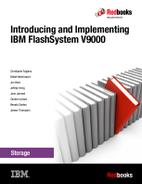
Figure 11-1 shows a two-site HA environment.
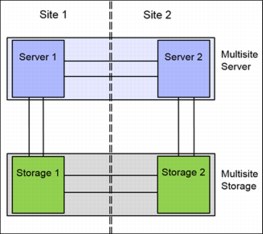
Figure 11-1 High availability environment
The HyperSwap function provides highly available volumes accessible through two sites at a distance up to 300 km apart. A fully-independent copy of the data is maintained at each site. When data is written by hosts at either site, both copies are synchronously updated before the write operation is completed. The HyperSwap function automatically optimizes itself to minimize data transmitted between sites and to minimize host read and write latency.
If the control enclosures, storage enclosures, or any other attached storage at either site go offline, leaving an online and accessible up-to-date copy, the HyperSwap function will automatically fail over access to the online copy. The HyperSwap function also automatically resynchronizes the two copies when possible.
11.1.1 HyperSwap Implementations
The decision for a HyperSwap failover can be managed by the host or by the storage system. IBM currently has two main solutions:
•Host-based HyperSwap. The host handles storage failures.
•Storage-based HyperSwap. The storage system handles storage failures.
The next two sections describe these two solutions.
Host-based HyperSwap
A HyperSwap function is available when using the IBM DS8000 family of products together with IBM PowerHA® System Mirror for AIX or IBM Geographically Dispersed Parallel Sysplex™ (IBM GDPS®) for IBM z/OS®. The HyperSwap functions on those environments use specific software on that host system. All decisions in split scenarios are made by the host.
Figure 11-2 shows a host-based HyperSwap example of an IBM AIX PowerHA and IBM System Storage DS8000 HyperSwap setup.
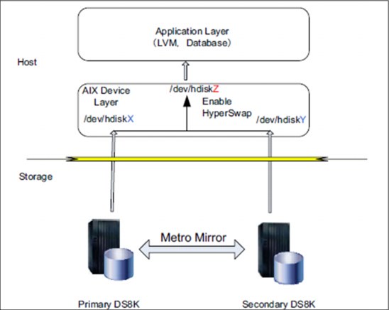
Figure 11-2 Host-based HyperSwap example
Storage-based HyperSwap
IBM Spectrum Virtualize provides the HyperSwap feature in the virtualization layer. It uses technologies from:
•Metro Mirror
•Global Mirror with Change Volumes
•Non-disruptive Volume Move
One volume is presented to the host from two different sites. Two IO groups are presenting the same volume to the host. All decisions in split scenarios are made by IBM Spectrum Virtualize software running on IBM FlashSystem V9000.
The host must detect, accept, and handle HyperSwap changes, and manage the application failover. All FlashSystem V9000 failover decisions are valid for all hosts, or host clusters attached to the FlashSystem V9000 cluster.
Figure 11-3 shows a IBM Spectrum Virtualize-based HyperSwap example. It shows that four VDisks are needed to present one HyperSwap volume to the host.

Figure 11-3 IBM Spectrum Virtualize-based HyperSwap example
The HyperSwap function in the FlashSystem V9000 software works with the standard multipathing drivers that are available on a wide variety of host types, with no additional host support required to access the highly available volume. Where multipathing drivers support Asymmetric Logical Unit Assignment (ALUA), the storage system tells the multipathing driver which control enclosures are closest to it, and should be used to minimize I/O latency. You must assign a site value to the host, to the FlashSystem control enclosures, and storage enclosures. The ALUA supporting multipathing driver configures the host pathing optimally. Details about the configuration are described in 11.5, “Configuration” on page 496.
|
Tip: When using the HyperSwap function, configure your host multipath driver to use an ALUA-based path policy.
|
11.2 HyperSwap design
This section provides high-level information about HyperSwap. Details are described throughout the whole chapter.
The IBM FlashSystem HyperSwap function is an active-active mirror based on Metro Mirror technology. It is an unstoppable configuration. The relationship of a HyperSwap volume is never in “stopped mode,” except during disaster recovery scenarios.
The LUN ID of the master VDisk is presented to the host. The auxiliary VDisk is always seen as offline in the GUI and CLI. The auxiliary VDisk is presented to the host with the same LUN ID as the master VDisk. HyperSwap simulates the master LUN ID for the auxiliary VDisk. The LUN ID of the auxiliary VDisk is not visible to the host.
Figure 11-4 shows the host can access the HyperSwap volume using the master and the auxiliary (aux) VDisk. In the CLI and GUI, the aux VDisk is shown offline, but the host can use it with the LUN ID of the master VDisk.
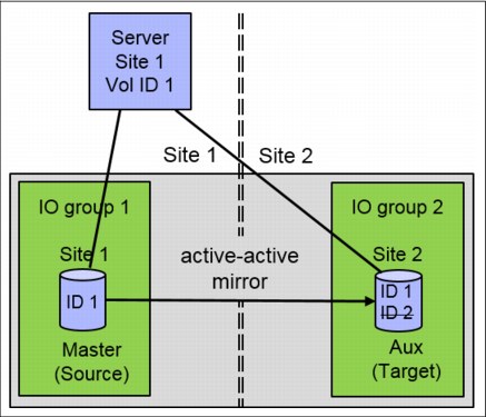
Figure 11-4 HyperSwap LUN ID Simulation
The host can access the HyperSwap volume using the I/O group on site 1, or the I/O group on site 2, or both. The multipath driver of the host is responsible for selecting the optimal paths.
The example in Figure 11-4 shows a host on site 1 accessing the HyperSwap volume using I/O group 1 and the master VDisk on site 1. Data is replicated to the auxiliary VDisk on site 2. When the connection from the host to the master VDisk is broken, for example the Fibre Channel (FC) connection between host and I/O group 1 is broken, then the host accesses the data using I/O group 2.
The master VDisk is still the primary VDisk, so reads are serviced by the master VDisk and writes are forwarded to the master VDisk and then replicated to the auxiliary or the secondary VDisk. If this scenario is running for more than 20 minutes, the auxiliary VDisk becomes the primary VDisk, servicing reads and writes. The master VDisk becomes the secondary VDisk. I/O arrives in I/O group 2 and is handled by the auxiliary (now primary) VDisk and replicated to the master (now secondary) VDisk.
A HyperSwap volume can be accessed concurrently for read and write I/O from any host in any site. All I/O is forwarded to one I/O group in the site with the primary VDisk. Using the site with the non-primary VDisk increases the long-distance traffic significantly.
HyperSwap Cluster monitors the workload and switches the copy direction if the most workload is arriving on the other site, optimizing performance.
Applications with equal workload pattern to the same HyperSwap volume using both I/O groups, for example Oracle RAC, are currently not optimal for HyperSwap.
|
Tip: If you are running VMware environment on top of HyperSwap, it is good practice to maintain VMs on the hosts in one site per HyperSwap volume. For example, with VMware Distributed Resource Scheduler (DRS), should run VM-host affinity rules.
|
A host accessing a HyperSwap volume uses two I/O groups. Therefore, the host multipathing must handle two times more paths compared to a normal volume. When changing from standard to HyperSwap topology, the host zoning has to be reviewed. Some hosts have limits for the optimal number of path to a LUN. If only HyperSwap volumes are configured on FlashSystem V9000, meaning each host accesses a volume using two I/O groups, the maximum number of host objects and the maximum number of volume mappings per host object is cut in half.
HyperSwap volumes use FlashCopy technology to provide consistency protection when synchronizing the master and auxiliary VDisk after a loss of sync, for example when the link between these VDisks was broken. One change volume per HyperSwap volume must be prepared on each site. Therefore, a HyperSwap volume requires the configuration of four internal VDisks. Two FlashCopy mappings to each change volume are required (one in each direction), so four FlashCopy maps are required per HyperSwap volume. all the needed VDisks and remote copy relationships are automatically generated when using the GUI or the CLI when creating a HyperSwap volume.
The auxiliary VDisk is offline because its ID is not shown to the host. The lsvdisk command shows all VDisks of a HyperSwap volume (Example 11-1).
Example 11-1 The lsvdisk command to display all VDisks of a HyperSwap volume
lsvdisk
id name IO_group_name status id mdisk_grp_name capacity volume_name function
0 HyperSwap_1 io_grp0 online mdiskgrp1 35.00GB HyperSwap_1 master
1 vdisk1 io_grp1 offline mdiskgrp2 35.00GB HyperSwap_1 aux
2 vdisk2 io_grp0 online mdiskgrp1 35.00GB HyperSwap_1 master_change
3 vdisk3 io_grp1 online mdiskgrp2 35.00GB HyperSwap_1 aux_change
Figure 11-5 shows the same HyperSwap volume by using the GUI.
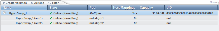
Figure 11-5 HyperSwap volume
The HyperSwap volume master VDisk status attribute of the lsvdisk command shows whether hosts are able to access data, for example whether the HyperSwap volume has access to up-to-date data or not. It does not show whether the master VDisk itself is actually online. The value status for auxiliary VDisk is always offline as shown in Example 11-1 on page 490.
The GUI information shows only the HyperSwap volume but not the four VDisks of a HyperSwap volume. The site attributes and the pool of the master VDisk and the auxiliary VDisk are shown. When creating a HyperSwap volume by using the GUI or the mkvolume command, then the master VDisk disk will be on site1 and the auxiliary VDisk on site 2. Their associated change volumes are created in the same pool as the master or the auxiliary VDisk.
Use the status attribute of the lsrcrelationship command to determine if a VDisk is online or offline. Possible values are online, primary_offline, secondary_offline, io_channel_offline, primary_change_offline, secondary_change_offline, and change_volumes_needed, as described in 11.13.3, “The lsrcrelationship or lsrcconsistgrp commands” on page 543. Use the lsvdisk command to get the name of the remote copy relationship of a HyperSwap volume (Example 11-2).
Example 11-2 HyperSwap volume lsvdisk status information
lsvdisk HyperSwap_1
...
RC_name rcrel0
...
The lsrcrelationship command shows the four VDisks of a HyperSwap volume, some lines are omitted for better readability (Example 11-3).
Example 11-3 The lsrcrelationship command
lsrcrelationship rcrel0
name rcrel0
master_vdisk_name HyperSwap_1
aux_vdisk_name vdisk1
primary master
state consistent_synchronized
status online
master_change_vdisk_name vdisk2
aux_change_vdisk_name vdisk3
Figure 11-6 shows the active-active relationship using the GUI.
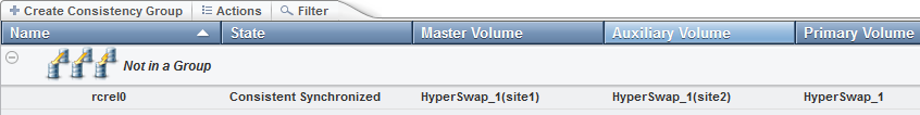
Figure 11-6 HyperSwap volume active-active relationship
The lsfcmap command shows the four FlashCopy mappings of a HyperSwap volume, as shown in Example 11-4.
Example 11-4 The lsfcmap command
lsfcmap
id name source_vdisk_id source_vdisk_name target_vdisk_id target_vdisk_name
0 fcmap0 0 HyperSwap_1 2 vdisk2
1 fcmap1 2 vdisk2 0 HyperSwap_1
2 fcmap2 1 vdisk1 3 vdisk3
3 fcmap3 3 vdisk3 1 vdisk1
Figure 11-7 shows the FlashCopy mappings using the GUI.
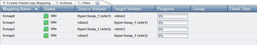
Figure 11-7 HyperSwap volume and its FlashCopy mappings
11.3 Comparison with Enhanced Stretched Cluster
Many of the aspects described so far are the same as those of the existing IBM Spectrum Virtualize Enhanced Stretched Cluster function, introduced in version 7.2 of the software. Table 11-1 provides a list of key differences between the Enhanced Stretched Cluster and HyperSwap functions.
|
Note: Enhanced Stretched Cluster is not supported with IBM FlashSystem V9000.
|
Table 11-1 Enhanced Stretched Cluster and HyperSwap comparison
|
Description
|
IBM Spectrum Virtualize Enhanced Stretched Cluster
|
IBM FlashSystem V9000 HyperSwap
|
|
Product availability
|
SAN Volume Controller only
|
FlashSystem V9000 with 2 or more I/O groups
|
|
Configuration
|
CLI or GUI
|
CLI or GUI
|
|
Sites
|
Two for data, third for quorum device
|
Two for data, third for quorum device
|
|
Distance between sites
|
Up to 300 km
|
Up to 300 km
|
|
Independent copies of data maintained
|
Two
|
Two (Four if additionally Volume Mirroring to two pools in each site)
|
|
Host requirements
|
Standard host multipathing driver
|
Standard host multipathing driver
|
|
Cache retained if only one site online?
|
No
|
Yes
|
|
Synchronization and resynchronization of copies
|
Automatic
|
Automatic
|
|
Stale consistent data retained during resynchronization for disaster recovery?
|
No
|
Yes
|
|
Scope of failure and resynchronization
|
Single volume
|
One or more volumes, user configurable
|
|
Ability to use FlashCopy together with high availability solution
|
Yes (although no awareness of site locality of data)
|
Limited
|
|
Ability to use Metro Mirror, Global Mirror, or Global Mirror with change volumes together with high availability solution
|
One remote copy
|
No, can use VDisk mirror for additional copies
|
|
Maximum highly available volume count
|
5000
|
1250
|
|
Licensing
|
Included in the base product
|
Requires Remote Mirroring license.
|
The Enhanced Stretched Cluster function and the HyperSwap function spread the control enclosures of the system across two sites, with additional storage at a third site acting as a tie breaking quorum device.
The topologies differ in how the control enclosures are distributed across the sites:
•Enhanced Stretched Cluster
For each I/O group in the system, the Enhanced Stretched Cluster topology has one control enclosure on one site, and one control enclosure on the other site. The topology works with any number (1 - 4) of I/O groups, but because the I/O group is split into two locations, this is only available with SAN Volume Controller, not FlashSystem V9000.
•HyperSwap
The HyperSwap topology locates both control enclosures of an I/O group in the same site, making this possible to use with either FlashSystem V9000 or SAN Volume Controller products. Therefore, to get a volume resiliently stored on both sites, at least two I/O groups are required.
The Enhanced Stretched Cluster topology uses fewer system resources, enabling a greater number of highly available volumes to be configured. However, during a disaster that makes one site unavailable, so the SAN Volume Controller system cache on the control enclosures of the surviving site is disabled.
|
Requirement: Using HyperSwap requires the Remote Mirroring license.
|
11.3.1 Disaster recovery
The HyperSwap function automatically controls synchronization and resynchronization of the master VDisk and the auxiliary VDisk. If the master VDisk and the auxiliary VDisk are out of sync, for example the data link to one site had been broken and is fixed again, FlashSystem V9000 will automatically resynchronize the data. Just before resynchronizing data to a VDisk copy, that copy usually contains crash-consistent but stale (out-of-date) data. The storage system automatically retains that consistent data during the resynchronization process using change volume technology.
What this means is that if a problem occurs at the site with the online copy before resynchronization completes, taking that copy offline, you have the opportunity to manually enable read and write access to the consistent, older copy of data, allowing the use of this data for disaster recovery. This option would typically be taken if you know that the offline copy will remain offline for an extended period, and the consistent but older data is useful enough to keep your business running.
As normal with disaster recovery solutions that support business continuity with older data, after the problem is resolved restoring access to the offline copy, you can choose to either revert to that now-online copy, which before the disaster held the latest copy of the data, or continue to work on the stale data used during the disaster. With either choice, the other copy is resynchronized to match the chosen copy.
11.3.2 Consistency Groups
One major advantage of the HyperSwap function, compared to Enhanced Stretched Cluster, is that it is possible to group multiple HyperSwap volumes together for high availability. Using consistency groups to control the synchronization and failover across many HyperSwap volumes in an application ensures that all VDisk copies on a site have data from the same point in time, enabling disaster recovery using that site’s VDisk copies. It also ensures that at least one site has an up-to-date copy of every HyperSwap volume in the consistency group. It further ensures that the other site, if it does not have an up-to-date copy of every VDisk, it has a consistent copy of every VDisk for some out-of-date point-in-time.
The following scenario is an example where the data is not consistent across all those volumes and would affect availability:
1. Site 2 goes offline.
2. Application continues to write to its volumes, changes only applied to site 1.
3. Site 2 comes online again.
4. Volumes are resynchronized back to site 2.
5. Site 1 goes offline during the resynchronization, leaving some volumes already resynchronized and some volumes unresynchronized.
Site 1 is the only site that has usable data. Site 2 might have usable data on some VDisks but not others. If this process is continued, it is possible that neither site will have a complete copy of data, making a failure on either site affect production I/O.
Without consistency groups, site 2’s data would have been made inconsistent on several of the VDisks, by the attempt to resynchronize, which did not complete. The unresynchronized VDisks contain consistent but old data, as described in 11.3.1, “Disaster recovery” on page 494. Site 2 now has some VDisks with old data and VDisks with resynchronized data. If site 1 data cannot be recovered, another solution is needed to recover business operations.
11.3.3 HyperSwap restrictions for software version 7.7.1
The following restrictions apply to the HyperSwap function for software version 7.7.1:
•Cluster internal Metro Mirror is used for replication, so the size of a HyperSwap volume cannot be changed using expandvdisksize and shrinkvdisksize commands.
•A cascaded Remote Copy is currently not available. HyperSwap volumes cannot be replicated to a second, independent storage system using Remote Copy functionality.
•Four FlashCopy mappings are required for each HyperSwap volume, which limits the number of HyperSwap volumes to 1250. Additional FlashCopy requirements will reduce the number of possible HyperSwap volumes.
Check the Configuration Limits and Restrictions:
•FlashCopy usage can be complicated because the Metro Mirror source and target volume can switch during daily operation. For this reason, identification of the copy direction is required for a successful FlashCopy.
•The Remote Copy relationship must be removed first for a reverse FlashCopy operation. After a reverse FlashCopy, all HyperSwap related functions must be manually implemented again (Remote Mirror and FlashCopy relationships).
•IBM FlashCopy Manager is currently not supported with HyperSwap volumes.
11.4 Planning
Two steps are required to configure IBM FlashSystem V9000 for HyperSwap. The first step is to configure the components of the system correctly for the HyperSwap topology. The second step is to create HyperSwap volumes that use that topology.
The first step includes these high-level tasks:
1. Planning the SAN Configuration
2. Define the sites.
3. Configure the control enclosures.
4. Configure the FlashSystem V9000 internal storage.
5. Configure the external storage controllers
6. Define the quorum device.
7. Configure the hosts.
8. Configure the HyperSwap topology.
9. Configure synchronization rates.
You should plan to complete all steps to configure sites for control enclosures, storage enclosures, controllers, hosts, and the system topology in one session. Do not leave a system in production if only some of these steps have been performed.
The IBM FlashSystem V9000 storage enclosures and the optional SAS attached expansion enclosures are the IBM FlashSystem V9000 internal storage. The external storage controllers are the additional storage systems, such as an IBM Storwize V7000, which are attached to IBM FlashSystem V9000.
A 3-site setup is required (Figure 11-3 on page 488). Two sites are used as the main data center to provider two independent data copies. A quorum disk or an IP-based quorum can be used as quorum device. However, the quorum device must be placed in a third, independent site.
The quorum disk must be supported as an extended quorum device. More information about HyperSwap configuration details on extended quorum is in IBM Knowledge Center:
The IP quorum substitutes the active tie-breaker role of the quorum disk. Redundancy can be implemented by using multiple quorum applications, similar to multiple quorum disks. However, only one application is active at a time, the other applications are available if the active quorum device application fails.
IBM Knowledge Center has more information about quorum disk:
11.5 Configuration
Several system objects must be configured before selecting the HyperSwap system topology, including sites, AC2 (or AC3) control enclosures, AE2 storage enclosures, storage controllers, and hosts.
11.5.1 SAN Configuration
Two IBM FlashSystem V9000 scalable building blocks in one cluster are required: each scalable building block is placed in one main site. Appropriate Fibre Channel (FC) or Fibre Channel over Ethernet (FCoE) connections are required between both sites. Check the references on configuration limits and restrictions in 11.3.3, “HyperSwap restrictions for software version 7.7.1” on page 495.
The two main SAN configurations options are:
•Configuration with inter-switch links (ISLs) between both sites.
•Configuration without ISLs between both sites.
In a configuration with ISLs between both sites, a division of the SAN infrastructure in a public and a private SAN is required. More details about requirements and use cases for HyperSwap system configuration are available in IBM Knowledge Center:
A quorum device in a third, independent site is required. See 11.4, “Planning” on page 496.
Connection between both main sites
Metro Mirror is used for HyperSwap, so the Metro Mirror bandwidth requirements are the minimum requirements extended by HyperSwap specific requirements. The total required bandwidth between both sites depends on the SAN configuration (with or without ISL), the host peak workload, and the expected growth rate.
FlashSystem V9000 uses IBM FlashSystem MicroLatency modules and is built for low latency requirements. Therefore the SAN must provide lowest latency.
|
Important: The SAN must sustain IBM FlashSystem V9000 lowest latency.
|
Configuration with ISL
A bandwidth equal to the peak write bandwidth (as sum from all hosts) is required for intersite communication between I/O groups. This bandwidth must be available in the private SAN. Additionally, you need intersite bandwidth in the public SAN for host-to-control enclosure read and write communication if a host accesses control enclosures in the other sites. For example, after a failure of the local I/O group of the host, or to access volumes that do not use the HyperSwap function. The guideline for a bandwidth equal to the peak write bandwidth for private SANs gives the minimal bandwidth supported for HyperSwap operations. In some non-optimal configurations, additional bandwidth is required to avoid potential performance issues. For example, if hosts at different sites share a volume, then the private SAN needs bandwidth equal to two times the peak write bandwidth plus the peak read bandwidth. Additional bandwidth is required for initial synchronization or resynchronization.
Therefore, the total required bandwidth can be calculated in the following way:
•Public SAN:
– Peak host read and write throughput
– Expected growth
•Private SAN:
– Peak host write throughput
– Surcharge for volumes used from hosts in both sites
– Bandwidth for initial synchronization and resynchronization
– Expected growth rate
However, in any case at least 4 Gbps are required in the private SAN, if the calculated bandwidth is below 4 Gbps. Consider the following example:
•Assume that the total host peak throughput is 30 GBps, 10 GBps are approximately write throughput.
•Assume that 20% of the peak host workload is created on volumes accessed from hosts at both sites such as in an Oracle Real Application Clusters (RAC) environment.
• Add 20% for initial synchronization and resynchronization.
•The expected growth is 50% in 3 years.
The simplified bandwidth calculation can be done in the according to the following tables.
Table 11-2 shows the calculation for public SAN.
Table 11-2 Public SAN calculation
|
Public SAN
|
Input
|
Formula
|
Result
|
|
Total host peak read and write throughput
|
30 GBps
|
|
30 GBps
|
|
Expected growth
|
50%
|
50% of 30 GBps
|
15 GBps
|
|
Total Public SAN bandwidth
|
|
30 GBps + 15 GBps
|
45 GBps
|
Table 11-3 shows the calculation for private SAN.
Table 11-3 Private SAN calculation
|
Private SAN
|
Input
|
Formula
|
Result
|
|
Peak host write throughput
|
10 GBps
|
|
10 GBps
|
|
Volumes used from hosts in both sites
|
20%, half of them use the wrong site, so effective 10%
|
10% of 10 GBps
|
1 GBps
|
|
Synchronization
|
20%
|
20% of 10 GBps
|
2 GBps
|
|
Subtotal
|
|
10 GB/s + 1 GB/s + 2 GBps
|
13 GBps
|
|
Expected growth
|
50%
|
50% of 13 GB/s
|
6.5 GB/s
|
|
Total Private SAN bandwidth
|
|
13 GBps + 6.5 GBps
|
19.5 GBps
|
So at least 45 GBps throughput are required for public SAN, and 19.5 GBps are required for the private SAN.
Configuration without ISL
The required bandwidth in a configuration without ISL is significantly lower compared to a configuration with ISL because IBM FlashSystem V9000 does not have to hold bandwidth in different SANs.
The following example uses the example discussed in “Configuration with ISL” on page 497:
•Assume that the total host peak throughput is 30 GBps, of which 10 GBps are write throughput.
•Assume that 20% of the peak host workload is created on volumes accessed from hosts at both sites like in an Oracle RAC environment.
•Add 20% for initial synchronization and resynchronization.
•The expected growth is 50% in 3 years.
The simplified bandwidth calculation can be done as shown in Table 11-4.
Table 11-4 Simplified bandwidth calculation
|
SAN
|
Input
|
Formula
|
Result
|
|
Peak host read and write throughput
|
30 GBps
|
|
30 GBps
|
|
Peak host write throughput
|
10 GB/S
|
|
|
|
Volumes used from hosts in both sites
|
20%, half of them use the wrong site, so effective 10%
|
10% of 10 GBps
|
1 GBps
|
|
Synchronization
|
20%
|
20% of 10 GBps
|
2 GBps
|
|
Subtotal
|
|
30 GBps + 1 GBps + 2GBps
|
33 GBps
|
|
Expected growth
|
50%
|
50% of 33 GBps
|
16.5 GBps
|
|
Total Private SAN bandwidth
|
|
33 GBps + 16.5 GBps
|
49.5 GBps
|
At least 49.5 GBps throughput is required in a configuration without ISL.
SAN design
A redundant design is suggested with two independent physical links between both sites, each link should be able to handle the calculated workload separately.
Management of the storage enclosure is using the FC connections between the control enclosure having the configuration node role and the storage enclosures. Every control enclosure can have the configuration node role and therefore every control enclosure must be zoned to every control enclosure.
Figure 11-8 shows a schematic zoning design to illustrate the need of FC path from every controller node to every storage enclosure. This is shown as Enclosure Zone in the figure.
The Internal Cluster I/O zone shown in Figure 11-8 is used for the control enclosure to control enclosure traffic. This includes the active-active mirroring traffic and must be sized accordingly.

Figure 11-8 Schematic zoning design
IBM Knowledge Center describes best practices for connecting components in a mirrored scalable system:
11.5.2 Defining the sites
The site corresponds to a physical location that houses the physical objects of the system. In a client installation, it can correspond to a separate office, an isolated fire zone, for example a separate office with a unique firewall address, a different data center building, or simply different rooms or racked areas of a single data center that has been planned to have internal redundancy.
Parameters that specify that a site exists are used in many of the commands described later. Table 11-5 on page 501 shows the four sites statically defined in the system.
Table 11-5 Site information
|
Site ID
|
Default site name
|
Objects that can be in site
|
Purpose
|
|
None
|
Has no name, cannot be renamed
|
Hosts, control enclosures, controllers, storage, and expansion enclosures
|
The default site for objects when they are not assigned to a specific site. The HyperSwap topology requires objects to be in a site.
|
|
1
|
site1
|
Hosts, control enclosures, controllers, storage, and expansion enclosures
|
The first of two sites to perform high availability between. Has no implied preferences compared to site 2.
|
|
2
|
site2
|
Hosts, control enclosures, controllers, storage, and expansion enclosures
|
The second of two sites to perform high availability between. Has no implied preferences compared to site 1.
|
|
3
|
site3
|
Controllers,
IP Quorum
|
A third site providing quorum abilities to act as a tie-break between sites 1 and 2 when connectivity is lost.
|
Sites 1, 2, and 3 can be renamed from the default name by using the chsite command and can be listed by using the lssite command (Example 11-5).
Example 11-5 The lssite command to rename default sites
chsite -name datacenter_west 1
chsite -name datacenter_east 2
chsite -name quorum_site 3
lssite
ID site_name
1 datacenter_west
2 datacenter_east
3 quorum_site
In Example 11-5, the chsite command is issued to rename site 1 as datacenter_west, site2 as datacenter_east, and site 3 as quorum_site. This can help you to understand and describe the location of objects in a more meaningful way. This document uses the default names site1, site2, and site3 for sites.
11.5.3 Control enclosures
With a HyperSwap system topology, all control enclosures in an I/O group must belong to the same site. You should assign the control enclosures of at least one I/O group to each of sites 1 and 2.
To configure HyperSwap volumes on IBM FlashSystem V9000, you need at least four control enclosures, two scalable IBM FlashSystem V9000 building blocks.
Before the HyperSwap system topology can be selected, the site of every control enclosure must be set by using either of the chnode command lines shown in Example 11-6.
Example 11-6 The chnode command to assign a site attribute to a control enclosure
chnode -site 1 node1
chnode -site site1 node1
This modifies the existing control enclosure node1 from its current site to site 1. This command must be used for all control enclosure.
|
Note: Every control enclosure of an I/O group must be in the same site. A control enclosure can never be assigned to site 3.
|
When the cluster topology is set to HyperSwap and an I/O group contains copies of HyperSwap volumes, the I/O group must stay in the same site even if all control enclosures were deleted from that I/O group. New control enclosures must be added with the same site attribute as the deleted control enclosures. The only way to move an I/O group from one site to the other is to remove all HyperSwap volume copies using that I/O group, delete the control enclosures from that I/O group, then re-add them to the I/O group but with the new site attribute.
Typically, a HyperSwap configuration might contain two or four building blocks, either with one I/O group on site 1 and one I/O group on site 2, or with two I/O groups on each of sites 1 and 2. A possibility is to configure the system with more I/O groups on one site than the other, although the site with fewer control enclosures might become a bottleneck.
Each I/O group should have sufficient bitmap capacity defined using the chiogrp command for the HyperSwap volumes in addition to the bitmap capacity requirements of other FlashCopy and Global Mirror or Metro Mirror objects needed.
11.5.4 Configuring the IBM FlashSystem V9000 storage enclosures
You must assign the site attribute to all IBM FlashSystem V9000 storage enclosures using the chenclosure command:
chenclosure -site <site id> <enclosure id>
For example, a two-building-block setup has two storage enclosures and their site attributes must be set. A site attribute for an expansion enclosure cannot be set because it is attached to control enclosures having a site attribute. Pools of the expansion enclosures will have the site information of the corresponding control enclosure.
Use the chenclosure command (Example 11-7) to assign the site attribute to the control enclosures.
Example 11-7 The chenclosure command to assign the site attribute
chenclosure -site 1 1
chenclosure -site 2 2
Example 11-8 The lsenclosure command to view site attribute details
lsenclosure
id status type product_MTM serial_number site_id site_name flashsystem
1 online expansion 9846-AE2 6855309 2 site2 yes
2 online expansion 9846-AE2 1310478 1 site1 yes
3 online expansion 9846-12F 7830019
IBM FlashSystem V9000 storage enclosures must be assigned to site 1 or site 2.
You cannot create a HyperSwap volume using a storage enclosure without a site attribute. The site attribute of a storage controller can be set before or after changing to the HyperSwap topology.
|
Note: Always assign a site attribute to IBM FlashSystem V9000 control, and storage enclosures before changing to HyperSwap topology.
|
11.5.5 Configuring the external storage controllers
For virtualized external storage, you must assign the site attribute to all controllers using the following command:
chcontroller –site <site id> <controller id>
Controllers should be assigned to site 1, site 2, or site 3 when used for quorum, if they have any managed MDisks and the system is set to use the HyperSwap topology. Mdisks can only be assigned to storage pools if they are allocated from a storage controller with a well-defined site that matches that of the storage pool.
You cannot create a HyperSwap volume using a storage controller without a site attribute. The site attribute of a storage controller can be set before or after changing to the HyperSwap topology.
11.5.6 Define quorum device
The quorum device can be implemented by using an external storage system, which must be assigned to the third site. Alternatively, an IP quorum application can be used to provide quorum. IBM Knowledge Center has more information:
To assign an external storage system to the third site, use commands in Example 11-9.
Example 11-9 Set site attribute for external storage controller
lscontroller
id controller_name ctrl_s/n vendor_id product_id_low
0 controller0_V7000 2076 IBM 2145
1 controller1_V7000 2076 IBM 2145
chcontroller -site 3 controller0_V7000
chcontroller -site 3 controller0_V7000
The HyperSwap environment requires an active quorum disk in site 3 and one quorum disk candidate in the other two main sites. The storage system V7000 is located in the third site and one managed disk is used as the active quorum disk. IBM FlashSystem V9000 storage enclosure spare disks drives are used in site 1 and site 2 as quorum disk candidates. The IBM FlashSystem V9000 cluster should not be able to change the quorum disk settings, so the override yes flag must be used with the chquorum command. Also, use the -active parameter to be sure that the quorum disk on the tie-breaker site is active. Use the chquorum command to set the tie-breaker quorum disk:
quorum -active -mdisk <mdisk of site 3> -override yes <quorom id>
The controller providing the quorum storage has to specify “extended quorum” support on the SAN Volume Controller supported controller list for the installed software release.
Using the IP quorum application as a tie-breaker
You can us the IP quorum application if no storage is available at the third site. IBM Knowledge Center has more details:
When the IP quorum application is running, it is automatically detected as third quorum device (Example 11-10).
Example 11-10 IP quorum disk
lsquorum
quorum_index status id active object_type override site_id site_name
0 online 11 no drive no 1 site1
2 online 23 no drive no 2 site2
3 online yes device no x3690-x5/<ip-address>
11.5.7 Configuring the hosts
Host objects have a site parameter. This parameter can be configured on existing host objects as follows:
chhost –site 1 Host_AIX
This command defines the ports of host Host_AIX as being on site 1. If the System is in HyperSwap topology you can use the GUI to assign a site to the host.
|
Important: The system dynamically configures host multipathing so that hosts in site 1 preferentially send I/O to control enclosures in site 1, and similarly for site 2. So for optimum performance, all of the WWPNs associated with this host object should be on that site. For clustered host systems attached to both sites, you should define a host object per site to optimize the I/O for each physical server in the clustered host system.
|
New hosts can be added with a defined site by using the following command:
mkhost -fcwwpn <WWPN:WWPN> –site <site id>
When HyperSwap volumes are mapped to a host by using the mkvdiskhostmap command, the host must be assigned to either site 1 or site 2.
By default, host objects are associated with all I/O groups. If you use the -iogrp parameter for the mkhost command to override this, be sure that hosts accessing HyperSwap volumes are associated with at least the I/O groups that the master and auxiliary VDisk of the HyperSwap volumes are cached in. Missing an association between the host and such an I/O group prevents the host from being able to access HyperSwap volumes through both sites.
|
Notes:
•A HyperSwap volume has two accessible I/O groups. A HyperSwap volume can be mapped only to a host having access to all accessible I/O groups of the HyperSwap volume.
•A Fibre Channel attached host will show the degraded status, if not zoned to all control enclosures belonging to the caching and accessible I/O groups of a mapped HyperSwap volume.
|
11.5.8 Configuring the HyperSwap topology
All control enclosures, storage enclosures, and storage controllers can be set to any of sites 1 or 2 (or 3 for controllers) when the system has been set to the standard system topology. Use the command lssystem to check the current topology, as shown in Example 11-11.
Example 11-11 The lssystem command to check current topology
lssystem
...
topology standard
...
Figure 11-9 shows the FlashSystem V9000 GUI in standard topology.
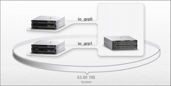
Figure 11-9 FlashSystem V9000 GUI with standard topology
Before the system can be set to the HyperSwap system topology, every control enclosure must have a site configured correctly, and it is advisable to set the site of every storage enclosure, expansion enclosure, storage controller, and host too for existing systems. For a new system, you can choose the HyperSwap topology early in your initial configuration, which helps ensure that objects have their sites set correctly.
When all of the sites have been set, the system can be set to use the HyperSwap topology using the chsystem command:
chsystem –topology hyperswap
Figure 11-10 shows the IBM FlashSystem V9000 GUI in HyperSwap topology.
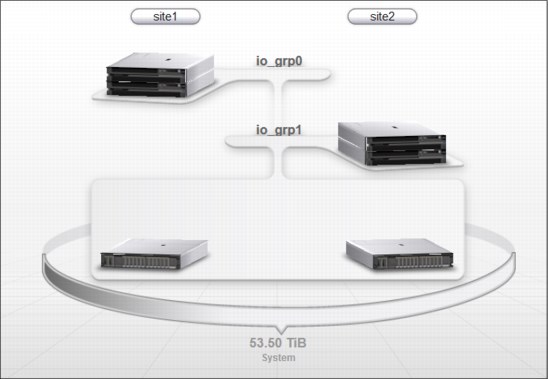
Figure 11-10 FlashSystem V9000 GUI with HyperSwap topology
The site attributes of the control enclosures, and storage enclosures had been set before enabling HyperSwap.
|
Note: You will not be able to change the topology back to the standard topology if any HyperSwap volumes are defined.
|
11.5.9 Configuring synchronization rates
Two primary factors affect the synchronization rate and are similar to those for the existing Metro Mirror and Global Mirror replication technologies:
•Partnership bandwidth
The total bandwidth between site 1 and 2. This is foreground traffic, such as transferring new host writes to the second site, and background traffic, such as synchronization of new HyperSwap volumes or resynchronization.
You can limit the background traffic of HyperSwap volumes. Limiting the amount of background traffic assures a minimum value for foreground traffic.
•Relationship bandwidth
This is the background traffic limitation per VDisk.
Partnership bandwidth
The primary attribute to configure is the partnership bandwidth. Before the introduction of HyperSwap volumes, this could not be configured for intra-cluster relationships (for example, with both copies in the same system), such as the active-active relationships used for HyperSwap replication. With HyperSwap-capable systems, the local partnership bandwidth can be configured, and represents the amount of physical bandwidth between sites used
for synchronization.
for synchronization.
For compatibility with earlier versions, this defaults to 25 MBps (200 Megabits per second) dedicated to synchronization, which can be appropriate for a small environment. For larger systems, or systems with more bandwidth available between sites, you might want to increase this by using the following command:
chpartnership -linkbandwidthmbits 4000 -backgroundcopyrate 20 <localCluster>
In this command, you can specify the bandwidth between sites, and how much can be used for synchronization. <localCluster> should be replaced by the name of the local system.
The -linkbandwidthmbits parameter specifies the aggregate bandwidth of the link between two sites in megabits per second (Mbps). It is a numeric value 15 - 100000. The default is 200, specified in megabits per second (Mbps). This parameter can be specified without stopping the partnership.
The -backgroundcopyrate parameter specifies the maximum percentage of aggregate link bandwidth that can be used for background copy operations. It is a numeric value 0 - 100, and the default value is 100, which means that a maximum of 100% of the aggregate link bandwidth can be used for background copy operations.
As with other types of partnership configuration, the system does not yet use the total amount of bandwidth available in any performance tuning, and only uses the resulting background copy bandwidth to determine HyperSwap synchronization rate. So the previous command could also be expressed as the following command:
chpartnership -linkbandwidthmbits 800 –backgroundcopyrate 100 <localCluster>
This command has the same effect concerning the background traffic, but the earlier command reserves 3200 MBps for foreground VDisk traffic.
The system will attempt to synchronize at the specified rate for background traffic where possible if there are any active-active relationships that require synchronization (including resynchronization after a copy has been offline for some time). This is true no matter how much new host write data is being submitted requiring replication between sites, so be careful not to configure the synchronization rate so high that this synchronization bandwidth consumption affects the amount needed for host writes.
Relationship bandwidth
The other control of how fast a relationship can synchronize is the system setting relationship_bandwidth_limit. This setting configures the maximum rate at which synchronization I/O is generated for a HyperSwap volume. It is shown with the lssystem command (Example 11-12).
Example 11-12 Using lssystem, maximum rate synchronization I/O is generated for a volume
lssystem
...
relationship_bandwidth_limit 25
...
By default this is 25 MBps, this is megabytes, not the megabits of the partnership configuration. This means that no matter how few relationships are synchronizing, the most synchronization I/O that is generated per HyperSwap volume is 25 MBps (this is 25 MBps of reads on the up-to-date copy, and 25 MBps of writes on the other copy).
If your system has storage that cannot handle the additional 25 MBps of I/O, you can configure this to a lower value using the chsystem command:
chsystem –relationshipbandwidthlimit 10
If you want to accelerate synchronization when there aren’t many HyperSwap volumes synchronizing, you might want to increase it to a higher value:
chsystem –relationshipbandwidthlimit 200
The -relationshipbandwidthlimit parameter specifies the new background copy bandwidth in megabytes per second (MBps), 1 - 1000. The default is 25 MBps. This parameter operates system-wide and defines the maximum background copy bandwidth that any relationship can adopt. The existing background copy bandwidth settings that are defined on a partnership continue to operate, with the lower of the partnership and volume rates attempted.
|
Note: Do not set this value higher than the default without establishing that the higher bandwidth can be sustained.
|
11.5.10 HyperSwap configuration using the GUI wizard
HyperSwap configuration is possible to do by using the GUI. With V7.7, only a storage controller as quorum on the third site is supported during the GUI wizard configuration.
Complete these steps:
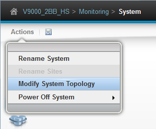
Figure 11-11 Modify System Topology
The Modify System Topology welcome page opens (Figure 11-12).

Figure 11-12 Modify System Topology wizard welcome page
2. Assign the site names (Figure 11-13).
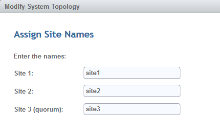
Figure 11-13 Assign site names
3. In this example, the default site names are used. Assign the control enclosures to sites (Figure 11-14).
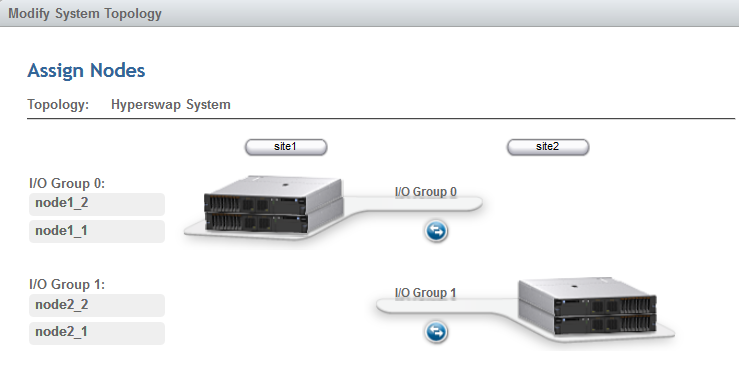
Figure 11-14 Assign control enclosures (nodes) to sites and I/O groups
4. Assign hosts to a site (Figure 11-15).
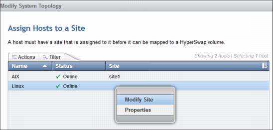
Figure 11-15 Optional host site attributes
5. The site assignment for hosts is optional. Assign the site attributes to the storage enclosure (Figure 11-16).
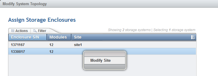
Figure 11-16 Storage enclosure site attributes
6. Assign the site attributes to the external storage controllers (Figure 11-17).
|
Note: At least one storage system must be assigned to the quorum site. IP quorum can not be defined using the modify topology wizard.
|
In this example an external IBM Storwize V7000 will be assigned to the third site.
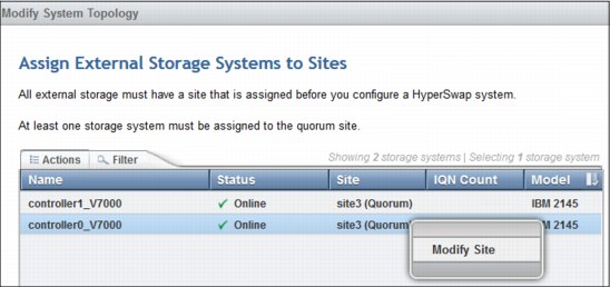
Figure 11-17 Storage controller site attributes
7. The Storwize V7000 will be used as quorum device at the third site. Set the bandwidth limits between sites (Figure 11-18).
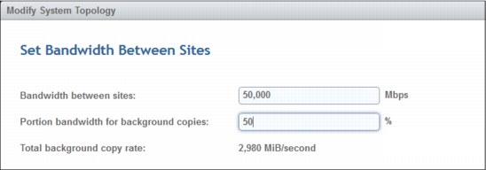
Figure 11-18 Bandwidth settings
Before the changes can be applied, a summary is displayed (Figure 11-19).
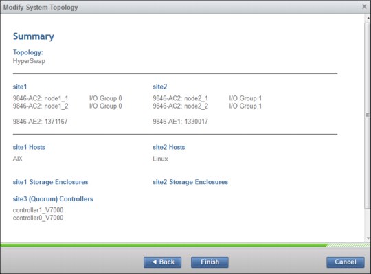
Figure 11-19 Summary of the GUI wizard
8. Click Finish. The HyperSwap configuration starts. After the tasks are completed, the system is in HyperSwap topology.
9. Manually set the quorum disk for the third site as described in 11.5.6, “Define quorum device” on page 503.
|
Note: The quorum device for the third site must be defined manually.
|
11.5.11 SAN environment for low latency
IBM FlashSystem V9000 provides lowest latency. A HyperSwap volume resides on two sites. Therefore between both sites, a minimal SAN latency is required. The IBM FlashSystem V9000 latency as seen by the host is depending on the SAN latency between the I/O groups on both sites. The write acknowledgement to the host will be done after both sites receive the data. So, the latency of the SAN between both sites is added to the latency as seen by the host.
|
Note: Lowest SAN latency is needed to preserve IBM FlashSystem V9000 lowest latency.
|
11.5.12 Creating HyperSwap volumes
HyperSwap capability enables each HyperSwap volume to be presented by two I/O groups. One VDisk on an I/O group of each site stores the data. Each of these two VDisks uses a VDisk on the same site as change volume. When the relationship between these four VDisks is defined, one VDisk is the master VDisk, the other VDisk is the auxiliary VDisk, and these two VDisks have an associated Change Volume. The two VDisks are kept synchronized by the IBM Spectrum Virtualize HyperSwap functions. The host only sees one HyperSwap volume. This HyperSwap volume has the LUN ID from the master VDisk.
Figure 11-20 shows the four VDisks and the HyperSwap volume presented to the host. The host always sees a HyperSwap volume with ID 1. The VDisk with ID 2 is synchronized with the VDisk with ID 1. If the host detects a HyperSwap volume on both I/O groups, both VDisks show ID 1 to the host. If the hosts multipathing driver is Asymmetric Logical Unit Access (ALUA) aware then the hosts multipathing driver detects and uses the preferred control enclosure for I/O.
In case of a failover, for example I/O group 1 is offline, the host accesses site 2 and uses VDisk 2, which presents ID 1 to the host. Even if internally there are different IDs, the host always sees the master ID 1. Therefore, the multipathing driver of the host can switch seamlessly to site 2.
Figure 11-20 shows four VDisk and the HyperSwap volume.

Figure 11-20 The HyperSwap volume build out of four VDisks
The GUI offers an easy-to-use management interface during the HyperSwap volume creation process. Click Volumes → Volumes → Create Volumes and then select HyperSwap. The HyperSwap wizard guides you through the volume creation process (Figure 11-21). The volume capacity, the volume name, and the pools in each site must be set. Use of additional functions such as thin provisioning and compression are optional settings. Settings related to I/O groups can be modified.
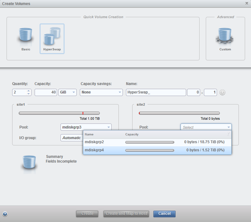
Figure 11-21 HyperSwap select pools
The setup in Figure 11-21 shows select pool mdiskgrp3 on site 1.
For site 2, two possible pools are shown. Make sure to select pools with the same latency for HyperSwap volumes. This example shows the creation of two HyperSwap volumes (Figure 11-22).
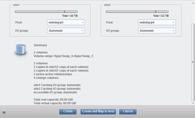
Figure 11-22 HyperSwap volume summary
The new HyperSwap volume is visible in the GUI (Figure 11-23) by selecting Volumes → Volumes. Only HyperSwap Master and Auxiliary volumes are shown in the GUI; the required FlashCopy volumes are hidden to reduce the level of complexity.
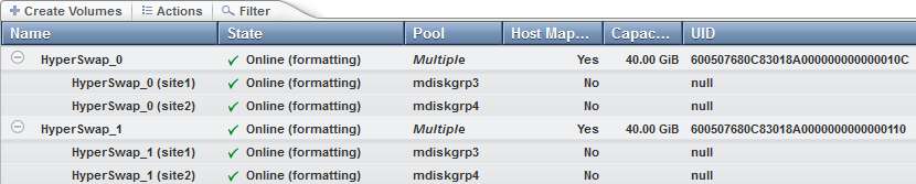
Figure 11-23 HyperSwap volumes
HyperSwap volumes will always be formatted. Hovering over the state of the HyperSwap volume provides the estimated completion time (Figure 11-24).
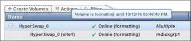
Figure 11-24 Formatting time
The lsvdiskprogress command displays the estimated completion time (Example 11-13).
Example 11-13 Estimating formatting completion time
lsvdiskprogress
id progress estimated_completion_time
0 2 161012154640
1 2 161012154637
4 2 161012154636
5 2 161012154642
Example 11-14 shows the HyperSwap master, auxiliary VDisks, and the associated change volumes. The change volumes will be automatically created using the same pool as the master or auxiliary VDisks respectively.
Example 11-14 lsvdisk information of HyperSwap volumes
lsvdisk
id name IO_group_name status disk_grp_name RC_name volume_name function
0 HyperSwap_0 io_grp0 online diskgrp1 rcrel0 HyperSwap_0 master
1 vdisk1 io_grp1 offline diskgrp2 rcrel0 HyperSwap_0 aux
2 vdisk2 io_grp0 online diskgrp1 rcrel0 HyperSwap_0 master_change
3 vdisk3 io_grp1 online diskgrp2 rcrel0 HyperSwap_0 aux_change
4 HyperSwap_1 io_grp0 online diskgrp1 rcrel1 HyperSwap_1 master
5 vdisk4 io_grp1 offline diskgrp2 rcrel1 HyperSwap_1 aux
6 vdisk5 io_grp0 online diskgrp1 rcrel1 HyperSwap_1 master_change
7 vdisk6 io_grp1 online diskgrp2 rcrel1 HyperSwap_1 aux_change
11.5.13 Creating a HyperSwap volume from a basic volume
Existing VDisks can be easily converted to a HyperSwap volume by using the addvolumecopy command or the GUI. Use the Add Volume Copy option from the context menu of a basic volume (Figure 11-25).
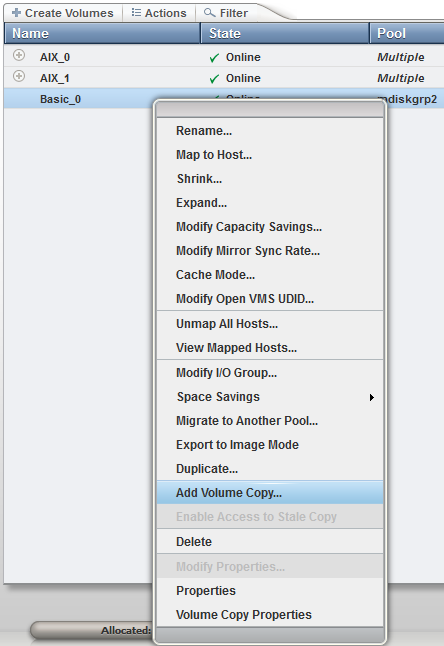
Figure 11-25 Add volume copy
Enter the appropriate values for the other site in the Add Volume Copy wizard. Figure 11-26 shows a basic volume on site 2, which will get a volume copy on site 1.
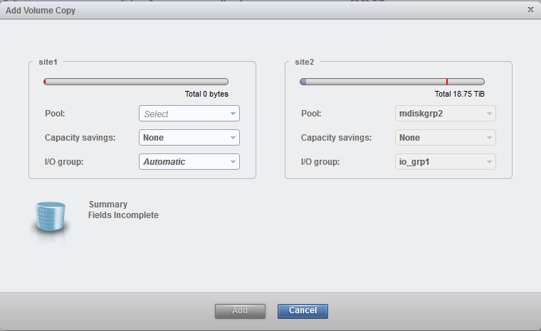
Figure 11-26 Add volume wizard
The running task information displays the progress of the HyperSwap volume synchronization (Figure 11-27).
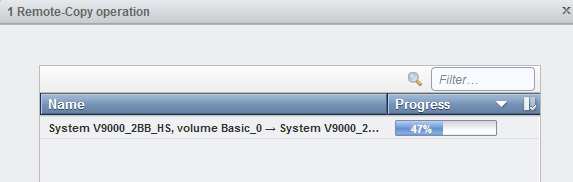
Figure 11-27 Running tasks information
11.5.14 Mapping HyperSwap volumes to a host
Mapping a HyperSwap volumes to a host is the same process as mapping a basic volume to the host by using the CLI or the GUI.
11.6 Operations
The active-active relationship has a primary attribute like regular Metro Mirror and Global Mirror relationships. This is set to either master or aux. With an active-active relationship, the VDisk in one I/O group acts as the primary, supplying data for reads, and serializing writes. All reads and writes must be initially processed by that I/O group. This is the method where writes are consistently applied to the HyperSwap volumes.
The HyperSwap function optimizes the I/O traffic. HyperSwap monitors which I/O group gets most of the host I/O. The VDisk of the HyperSwap volume used by the host with the same site ID as the I/O group with most of the hosts I/O should act as primary.
From an initially created HyperSwap volume, the master VDisk acts as the primary. If the first I/O to this HyperSwap volume is submitted only to the auxiliary VDisk’s site for approximately more than 10 minutes, then the system switches the direction of the relationship. The hosts have improved read and write performance. The secondary VDisk of this HyperSwap volume is now the primary VDisk and the master VDisk is now the auxiliary VDisk. The active-active relationship is now reversed.
HyperSwap Volumes with most IO going to the secondary VDisk’s site will reverse (or swap) the active-active relationship. The secondary VDisk of this HyperSwap volume will be the primary VDisk and the master VDisk will be the auxiliary VDisk. The time frame of the swap is depending on the IO load and is optimized by IBM FlashSystem V9000.
HyperSwap volumes in consistency groups all switch direction together, so the direction that a set of active-active relationships in a consistency group replicates will depend on which of the two sites has most of the host I/O across all HyperSwap volumes.
To create a consistency group select Copy Services → Remote Copy → Create Consistency Group. The Create Consistency Group wizard opens (Figure 11-28).
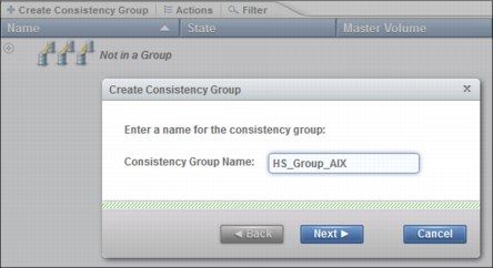
Figure 11-28 HyperSwap consistency group creation
The wizard guides you through the steps.
The auxiliary volumes are located on the same system, so select the appropriate option (Figure 11-29) and create an empty consistency group.
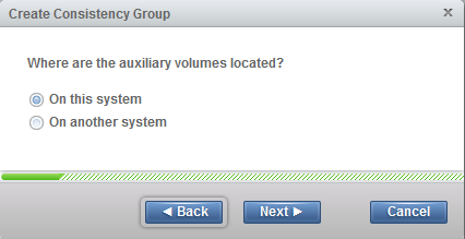
Figure 11-29 Consistency group system selection
Select the remote copy relationships you want to move to the consistency group and add them to the consistency group by using the Actions menu of the remote copy relationships (Figure 11-30).
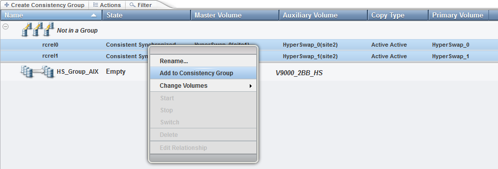
Figure 11-30 Adding remote copy relationships to a consistency group.
Figure 11-31 shows selection of the consistency group for the selected remote copy relationships.
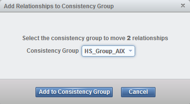
Figure 11-31 Selection the consistency group
Figure 11-32 shows that the master VDisk is the primary VDisk. The consistency group contains the relationships of the two volumes HyperSwap_0 and HyperSwap_1.
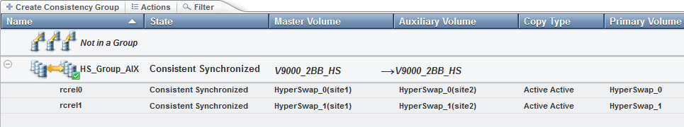
Figure 11-32 HyperSwap normal copy direction
Figure 11-33 shows that the auxiliary VDisk is now the primary VDisk. You see the changed direction of the arrow with the freeze time of the master VDisks. The master VDisk in this consistency group is stopped at the same point in time, because one of the master VDisks went offline to keep a consistent state of all master VDisks in this consistency group.
Next to the state, a sign is added to show that master and auxiliary VDisks are now switched. Hovering over this sign displays this message. When the Primary Volume column is added to the view, you see the name of the current primary VDisk, and notice that the auxiliary VDisk acts as primary.
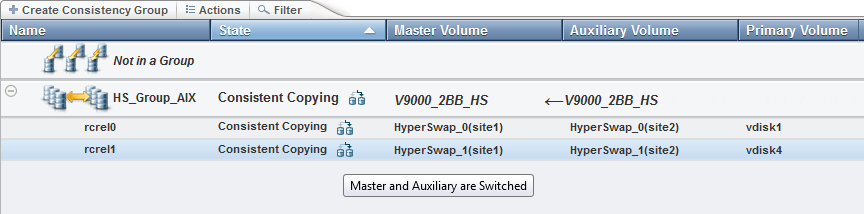
Figure 11-33 HyperSwap reversed copy direction, indicated by extra reverse sign and reversed arrow
|
Note: Most of the I/Os are currently a comparison of number of sectors written to rather than a count of I/Os. A 75% majority is required to switch to prevent frequent alternating
of direction. |
VMware systems can share data stores between multiple virtualized hosts using a single HyperSwap volume. To minimize cross-site I/O traffic, make sure that a data store is only used for virtual machines primarily running on a single site, as this enables HyperSwap to orient the replication optimally.
11.6.1 Site failure
Normally, the storage and control enclosures on both sites are online, and both copies of every HyperSwap volume, the master and auxiliary VDisk of every active-active relationship, contain up-to-date data. If a site fails so that IBM FlashSystem V9000 control enclosures, storage, Fibre Channel connectivity, or a combination is unavailable through hardware failure, power failure, or site inaccessibility, HyperSwap preserves access to VDisks through the remaining site.
A fully synchronized HyperSwap volume has the active-active relationship with the state consistent_synchronized. If the storage or control enclosures for the VDisk on one site of a fully synchronized HyperSwap volume goes offline, the following changes occur:
•The state of the active-active relationship becomes consistent_copying.
•Host I/O pauses for less than a second in a normal case (this can extend to multiple seconds in some cases, particularly with larger consistency groups).
•If the offline VDisk was the primary copy, the direction of the relationship switches to make the online copy the primary.
•The progress value of the active-active relationship counts down from 100% as the copies become more different (for example, if 10% of the HyperSwap volume was modified while one copy was offline, the progress value shows 90).
•The master VDisk remains online, and the auxiliary VDisk remains offline when viewed through the lsvdisk command, regardless of which copy is no longer accessible.
Figure 11-34 show the remote copy relationship in a configuration when the master VDisk is the primary VDisk.
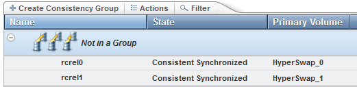
Figure 11-34 Remote copy relationships
Example 11-15 shows the same information using the CLI.
Example 11-15 Example of relationship changes after a fail over to the remote site
# relationship before fail over to the remote site
>lsrcrelationship rcrel0
name rcrel0
primary master
...
state consistent_synchronized
...
progress
freeze_time
status online
...
Example 11-16 shows the remote copy relationship after a failover to the remote site. Here the auxiliary VDisk is the primary VDisk. The differences between a running relationship shown in Example 11-15 on page 522 and, after a failover, to the remote site are highlighted in Example 11-16.
Example 11-16 Remote copy relationship after fail over to the remote site
# relationship after fail over to the remote site
>lsrcrelationship rcrel0
name rcrel0
primary aux
...
state consistent_copying
...
progress 38
freeze_time 2016/10/12/21/23/08
status secondary_change_offline
...
Figure 11-35 shows the reversed remote copy relationship after the site failure.
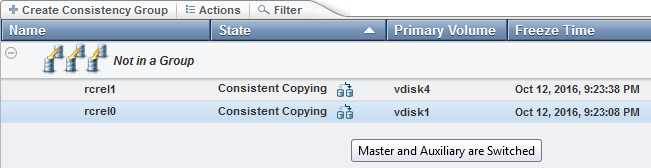
Figure 11-35 Remote copy reversed relationship
The failover in this example is due to an offline state of the control enclosures on site 1. Therefore the VDisk on site 1 was offline.
Figure 11-36 shows the offline information in the volume view.
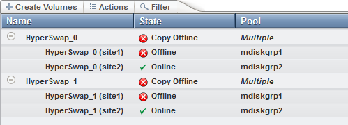
Figure 11-36 Site failure offline information
Table 11-6 shows the differences between the two lsrcrelationship commands. The master VDisk is offline and you can see by it looking at the primary, and status information. The status is secondary_offline and, because the auxiliary VDisk is primary, the secondary offline VDisk is the master VDisk.
Table 11-6 The lsrcrelationship changes
|
State
|
Before
|
After
|
|
primary
|
master
|
aux
|
|
state
|
consistent_synchronized
|
consistent_copying
|
|
progress
|
<null>
|
38
|
|
freeze_time
|
<null>
|
2016/10/12/21/23/08
|
|
status
|
online
|
secondary_change_offline
|
When that offline copy is restored, the progress value counts back up to 100 as the HyperSwap volume is resynchronized. When it has been resynchronized, the state of the active-active relationship becomes consistent_synchronized again. No manual actions are required to make this process occur.
Example 11-17 shows the relationship status after the master VDisk is online again. After the resynchronization completes (depending on the amount of data to be replicated, and new data coming in), the status is identical to the status before the master VDisk went offline. Only the lines different from the offline master are shown.
Example 11-17 Relationship status after volume is online and synchronized again
IBM_FlashSystem:TestCluster:superuser>lsrcrelationship rcrel0
primary master
state consistent_synchronized
progress
freeze_time
status online
During resynchronization, you see the FlashCopy mapping progress filled (Figure 11-37).
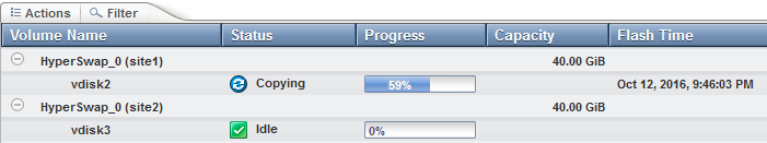
Figure 11-37 Flash Copy for volume HyperSwap_0 during resynchronisation
For HyperSwap volumes in consistency groups, a single HyperSwap volume with an inaccessible copy will cause this error recovery procedure to take place on every HyperSwap volume in the consistency group. Each active-active relationship becomes consistent_copying. This ensures the consistency of the VDisks on the auxiliary site. If one HyperSwap volume in a group already has one copy offline, and then a different HyperSwap volume VDisks in the same group goes offline, you see two different scenarios.
The rcrel0 and rcrel1 are in the same consistency group. Here is the current state of the HS_Vol_1_rel HyperSwap volume: The master VDisk went offline, then the auxiliary VDisk became primary for both HyperSwap volumes (Example 11-18).
Example 11-18 The lsrcrelationship command to see current state of volumes
lsrcrelationship rcrel0
primary aux
state consistent_copying
status secondary_offline
lsrcrelationship rcrel1
primary aux
state consistent_copying
status online
Now, one VDisk of the rcrel1 HyperSwap volume goes offline:
1. The offline VDisk is on the auxiliary site, the same site with the already-offline VDisk. In Example 11-19, the master VDisk, which is on the secondary site went offline. The HyperSwap volume is still online and accessible from the host.
Example 11-19 Master VDisk offline
lsrcrelationship rcrel0
primary aux
state consistent_copying
status secondary_offline
lsrcrelationship rcrel1
primary aux
state consistent_copying
status primary_offline
2. The offline VDisk is on the primary site, the site currently used for I/O. In Example 11-20, the auxiliary VDisk, which is on the current primary site went offline. The HyperSwap volume is now offline and not accessible from the host.
Example 11-20 Auxiliary VDisk offline
lsrcrelationship rcrel0
primary aux
state consistent_copying
status secondary_offline
lsrcrelationship rcrel1
primary aux
state consistent_copying
status primary_offline
HyperSwap was not able to hide the offline VDisk on the primary site of the HS_Vol_2_rel relationship. That HyperSwap volume went offline.
11.6.2 Converting a HyperSwap volume to a basic volume
To remove a copy from a HyperSwap volume, use the rmvolumecopy command. Example 11-21 shows two HyperSwap volumes and their VDisks and the result of the rmvolumecopy command. The copy on site 2, which is I/O group 1, will be removed from the second HyperSwap volume in this example.
Example 11-21 removing a HyperSwap volume copy
lsvdisk
id name IO_group_id IO_group_name volume_name function
0 HyperSwap_0 0 io_grp0 HyperSwap_0 master
1 vdisk1 1 io_grp1 HyperSwap_0 aux
2 vdisk2 0 io_grp0 HyperSwap_0 master_change
3 vdisk3 1 io_grp1 HyperSwap_0 aux_change
4 HyperSwap_1 0 io_grp0 HyperSwap_1 master
5 vdisk4 1 io_grp1 HyperSwap_1 aux
6 vdisk5 0 io_grp0 HyperSwap_1 master_change
7 vdisk6 1 io_grp1 HyperSwap_1 aux_change
rmvolumecopy -site 2 HyperSwap_1
lsvdisk
id name IO_group_id IO_group_name volume_name function
0 HyperSwap_0 0 io_grp0 HyperSwap_0 master
1 vdisk1 1 io_grp1 HyperSwap_0 aux
2 vdisk2 0 io_grp0 HyperSwap_0 master_change
3 vdisk3 1 io_grp1 HyperSwap_0 aux_change
4 HyperSwap_1 0 io_grp0 HyperSwap_1
The rmvolumecopy command has removed the auxiliary VDisks, the two change volumes, the four flash copy mappings and the HyperSwap remote copy relationship of the volume HyperSwap_1.
11.6.3 Deleting HyperSwap volumes
To delete a HyperSwap volume that contains data that is no longer required, use the rmvolume command or the GUI as though you were deleting a basic volume (Figure 11-38).
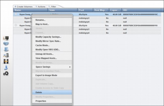
Figure 11-38 Deleting a HyperSwap volume
11.6.4 FlashCopy with HyperSwap volumes
FlashCopy can be used to take point-in-time copies of HyperSwap volumes.
A FlashCopy map with a HyperSwap volume as its source cannot cross sites. Therefore, a FlashCopy mapping where the target VDisk is on site 1 must use the VDisk of the HyperSwap volume on site 1 as its source, and likewise for site 2. It is not possible for a FlashCopy map with a HyperSwap volume as its source to copy data between sites.
For example, if a HyperSwap volume has VDisk 10 providing data on site 1, and VDisk 11 on site 2, FlashCopy maps can be created as follows using the mkfcmap command (Example 11-22).
Example 11-22 The mkfcmap command to create FlashCopy maps
mkfcmap -source 10 -target 12 ...
mkfcmap -source 11 -target 13 ...
In Example 11-22, VDisk 12 is a basic volume already created on site 1, and VDisk 13 on site 2. These two FlashCopy maps can both be used independently to take point-in-time copies of the HyperSwap volume on the two sites. The system provides no coordination of these maps.
When triggering the FlashCopy map, the copy of the HyperSwap volume on the same site as the FlashCopy target VDisk must be either of the following options:
•A primary copy of an active-active relationship in any state
•A secondary copy of an active-active relationship in a consistent_synchronized state
If access has been enabled to an old but consistent copy of the HyperSwap volume, a FlashCopy map can only be triggered on the site that contains that copy.
A FlashCopy map cannot be created with a HyperSwap volume as its target. If necessary, delete the active-active relationship to convert the HyperSwap volume to a basic volume before creating and triggering the FlashCopy map.
|
Note: A FlashCopy can only be taken from the VDisks of a HyperSwap volume, not from the HyperSwap volume itself. A FlashCopy cannot be restored on a VDisk of a HyperSwap volume. FlashCopy Manager is currently not supported with HyperSwap Volumes.
|
11.7 HyperSwap with SAS attached expansion enclosures
IBM FlashSystem V9000 manages internal storage. The internal storage are the AE2 storage enclosures and the optional SAS attached 12F/24F/92F expansion enclosures. Figure 11-39 shows an IBM FlashSystem V9000 setup with one optional storage enclosure on site 1.
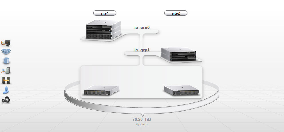
Figure 11-39 FlashSystem V9000 with optional expansion enclosures
This configuration uses one storage enclosure and one expansion enclosure on site 1. Site 2 uses one storage enclosure. Figure 11-40 on page 529 shows the corresponding pools.
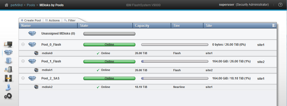
Figure 11-40 Pools corresponding to the two control enclosures, and one expansion enclosure
You can create a HyperSwap volume by using the HyperSwap volume wizard (Figure 11-41).
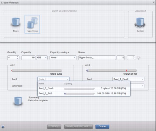
Figure 11-41 HyperSwap volume wizard
You can select either the storage enclosure pool (pool name: Pool_0_Flash) or the expansion enclosure pool (pool name: Pool_0_SAS) for the data on site 1. Site 2 does not show the select possibility because there is exactly one pool that is pre-selected.
To display the volumes dependent on expansion enclosures, from the GUI select Monitor → System, right-click the expansion enclosure, and then select Dependent Volumes (Figure 11-42).
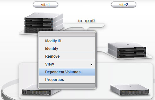
Figure 11-42 Expansion enclosure information
Figure 11-43 shows the expansion enclosures-dependent volumes.
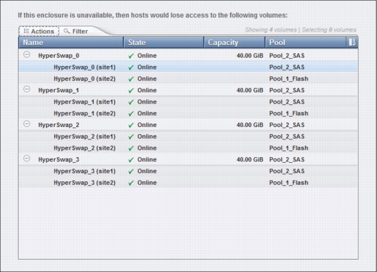
Figure 11-43 Expansion enclosure depending volumes
11.8 Disaster recovery with HyperSwap
The HyperSwap function automatically uses both copies to provide continuous host access to data, providing that both copies are up-to-date. If one copy is up-to-date, and the other is stale, and the up-to-date copy goes offline, the system cannot automatically use the remaining copy to provide high availability to the HyperSwap volume.
However, the user can choose to enable access to that stale copy. This is telling the system to rewind the state of that HyperSwap volume to the point in time of that stale copy.
This rewind to the point in time of that stale copy consists of manual steps, which must be done carefully. Before starting this process, you must make sure that the hosts have not cached data or status of the HyperSwap volumes. Ideally shut down host systems using the HyperSwap volume before taking these steps. Running these commands without these precautions might crash your applications and corrupt the stale copy.
To demonstrate a stale copy with an up-to-date copy going offline, check active-active relationship of a HyperSwap volume using the lsrcrelationship command while the HyperSwap volume is still resynchronizing, after the master had become offline and online again (Example 11-23).
Example 11-23 HyperSwap volume resynchronizing
IBM_FlashSystem:TestCluster:superuser>lsrcrelationship HS_Vol_2_rel
id 6
name HS_Vol_2_rel
master_cluster_id 000002032060460E
master_cluster_name TestCluster
master_vdisk_id 6
master_vdisk_name HS_Vol_2_Mas
aux_cluster_id 000002032060460E
aux_cluster_name TestCluster
aux_vdisk_id 8
aux_vdisk_name HS_Vol_2_Aux
primary aux
consistency_group_id
consistency_group_name
state consistent_copying
bg_copy_priority 50
progress 85
freeze_time 2016/09/29/12/08/31
status online
sync
copy_type activeactive
cycling_mode
cycle_period_seconds 300
master_change_vdisk_id 7
master_change_vdisk_name HS_Vol_2_Mas_CV
aux_change_vdisk_id 9
aux_change_vdisk_name HS_Vol_2_Aux_CV
Here, the site of the master copy had previously been offline, had returned online, and the HyperSwap volume is resynchronizing. The consistent_copying state of the HyperSwap volume shows a resynchronization where the master copy contains a stale image, and the value contained in the freeze_time field shows when that image dates from. The progress value is increasing toward 100 as the resynchronization process continues.
Now, the site of the auxiliary copy goes offline.
Check the active-active relationship using the lsrcrelationship command. Only the changes to the previous output are shown in Example 11-24. The HyperSwap volume is offline because the primary VDisk went offline during resynchronization.
Example 11-24 The lsrcrelationship command after the site of the auxiliary copy has gone offline
IBM_FlashSystem:TestCluster:superuser>lsrcrelationship HS_Vol_2_rel
...
state consistent_copying
bg_copy_priority 50
progress 87
freeze_time 2016/09/29/12/08/31
status primary_offline
...
With the only up-to-date copy of the HyperSwap volume offline, the active-active relationship cannot switch direction to keep the HyperSwap volume online, so the master VDisk is now offline. You see the offline master and auxiliary disk using the lsvdisk command (Example 11-25).
Example 11-25 The lsvdisk command shows the master VDisk offline
IBM_FlashSystem:TestCluster:superuser>lsvdisk
ID name IO_group_name status mdisk_grp_id mdisk_grp_name capacity
6 HS_Vol_2_Mas io_grp0 offline 0 mdiskgrp_west 35.00GB
7 HS_Vol_2_Mas_CV io_grp0 online 0 mdiskgrp_west 35.00GB
8 HS_Vol_2_Aux io_grp1 offline 1 mdiskgrp_east 35.00GB
9 HS_Vol_2_Aux_CV io_grp1 online 1 mdiskgrp_east 35.00GB
At this point, you look at the freeze_time value. If data from that date is not useful, for example it is from too long ago, or before a recent vital update, it might be best to wait until the offline up-to-date copy of the HyperSwap volume can be brought back online.
However, if the stale data is useful, and it is likely that the up-to-date copy of the HyperSwap volume will remain offline for an extended period of time (or will never come online again, for example after a fatal site failure), you can choose to enable access to the stale copy of the HyperSwap volume. Before running this command, make sure that no data or state from this HyperSwap volume is cached on host systems. Stop the active-active relationship using the stoprcrelationship command:
stoprcrelationship -access <relationship>
Check the active-active relationship using the lsrcrelationship command. Only the changes to the previous output are shown in Example 11-26. Stopping the relationship will take the HyperSwap volume online using the stale copy. The state of the relationship is idling.
Example 11-26 The lsrcrelationship command results after stopping the active-active relationship
IBM_FlashSystem:TestCluster:superuser>lsrcrelationship HS_Vol_2_rel
...
primary master
state idling
bg_copy_priority 50
progress
freeze_time
status
...
At this point, the data presented to hosts from this HyperSwap volume immediately changes to that stored on the stale copy. One way to think of this is that the HyperSwap volume has been consistently rolled back to the point in time denoted by the freeze_time value. The HyperSwap volume continues to be readable and writable at this point. You can start your business applications again, and continue from this stale image.
Replication is paused, even if the up-to-date copy becomes online again. This is because the previously stale image, which is now being accessed by hosts, and the previously up-to-date copy, which contains some changes not present on the previously stale image, are now divergent copies. The two copies were the same at the freeze_time point in time, but then each had different writes applied. Either copy might be the one that the user wants to keep in the long term.
So the system allows the user to choose which copy is more useful to them. This choice is made based on how much data was missing on the stale copy compared to the up-to-date copy, and how much progress has been made on the stale copy since access was enabled
to it.
to it.
The first step is determining which copy has the stale copy, which is currently accessible to hosts. This is either the master or auxiliary copy, and is visible under the primary attribute of the active-active relationship. You can choose between two scenarios:
•Keep using the copy that hosts are currently accessing, and discard the old up-to-date copy.
The other, previously up-to-date copy is online again. You decide not to use it, but to keep using the previously stale copy the host is currently accessing. This scenario is described in 11.8.1, “Using the VDisk that the hosts are currently accessing” on page 534.
•Go back to the up-to-date copy and discard the stale copy used for disaster recovery.
The other, old up-to-date copy is online again, and you decide to discard the changes on this copy and go back to the up-to-date copy. This scenario is described in 11.8.2, “Going back to the up-to-date copy” on page 535.
11.8.1 Using the VDisk that the hosts are currently accessing
This section describes using the stale copy and discarding the old up-to-date copy to start the active-active relationship of the HyperSwap volume.
The disaster recovery using the stale copy was successful and the host is now using that copy. You have decides that this copy, the stale copy, should be used and discarding the up-to-date copy. Use the lsrcrelationship command to detect the current primary VDisk (Example 11-27).
Example 11-27 The lsrcrelationship command to detect current primary
IBM_FlashSystem:TestCluster:superuser>lsrcrelationship <relationship>
primary master
or
primary aux
Use the startrcrelationship command to start the relationship:
startrcrelationship -primary <current_primary> -force <relationship>
In this example, <current_primary> is the current primary value of the active-active relationship, and is master or aux. The -force flag is there because after you make your decision, that loses the ability to use the copy that is not the primary, so it is telling the system that you are aware that this cannot be reverted. In this example, the command is as follows:
startrcrelationship -primary master -force HS_Vol_2_rel
The host is not affected using this command. There is no need to quiesce host I/O or take any further action. This command resumes HyperSwap replication, and copy across any regions that are different between the two copies to resynchronize as fast as possible. Both copies keep a bitmap of VDisk regions at a 256 KB granularity, used to record writes to that copy that have not yet been replicated to the other copy.
On this resynchronization, both sets of information are used to undo writes applied only to the old up-to-date copy, and also to copy across additional writes made to the stale copy during the disaster recovery. Because the disaster recovery only happened because the copies were resynchronizing before the up-to-date copy went offline, all differences from that interrupted resynchronization process are reverted on the old up-to-date copy now as well.
The active-active relationship goes into an inconsistent_copying state, and as copying continues, the progress increases toward 100. At that point, the relationship goes into a consistent_synchronized state, showing that both copies are up-to-date, and high-availability is restored.
Use the lsrcrelationship command to check the status (Example 11-28).
Example 11-28 HyperSwap volume relationship using stale copy, discarding the up-to-date copy
IBM_FlashSystem:TestCluster:superuser>lsrcrelationship HS_Vol_2_rel
ID 6
name HS_Vol_2_rel
master_cluster_id 000002032060460E
master_cluster_name TestCluster
master_vdisk_id 6
master_vdisk_name HS_Vol_2_Mas
aux_cluster_id 000002032060460E
aux_cluster_name TestCluster
aux_vdisk_id 8
aux_vdisk_name HS_Vol_2_Aux
primary master
consistency_group_id
consistency_group_name
state consistent_synchronized
bg_copy_priority 50
progress
freeze_time
status online
sync
copy_type activeactive
cycling_mode
cycle_period_seconds 300
master_change_vdisk_id 7
master_change_vdisk_name HS_Vol_2_Mas_CV
aux_change_vdisk_id 9
aux_change_vdisk_name HS_Vol_2_Aux_CV
11.8.2 Going back to the up-to-date copy
This section describes going back to the up-to-date copy and discarding the stale copy to start the active-active relationship of the HyperSwap volume.
The previous section described the steps keeping the stale copy used for disaster recovery used in the long term. It showed how to synchronize to the other copy.
This section describes the scenario when you decide to discard the writings made to the stale copy and go back to up-to-date copy, the one that held the latest data before the disaster recovery.
This scenario is different from the last one, because the image visible by hosts is going to change again. Just as enabling access to the stale copy required hosts to have no cached data from the HyperSwap volume, and ideally they should be fully shut down, the same is true of reverting to the up-to-date copy.
Before going further, make sure that no running hosts are going to be affected by the data changing, and have no stale data that they might corrupt the up-to-date copy with. When applying the startrcrelationship command the data visible to hosts instantly reverts to the up-to-date copy. Use the startrcrelationship command to start the relationship:
startrcrelationship -primary <current_secondary> -force <relationship>
In this example, <current_secondary> is the copy other than the current primary value of the active-active relationship, and is master or aux. In other words, if the primary field says master, use aux here, and vice versa. You cannot get back to the other set of data after you have run this command, and the -force flag is there to acknowledge this. In this example, the command is as follows:
startrcrelationship -primary aux -force HS_Vol_2_rel
The image visible to hosts instantly reverts to the up-to-date copy, so it reverts as soon as you have run this command. You can bring the hosts back online and start using this HyperSwap volume again.
As with the other scenario, the active-active relationship is in an inconsistent_copying state while resynchronizing, and again this resynchronization uses the bitmaps of writes to each copy to accelerate this resynchronization process. When the copies are fully synchronized, the relationship goes back to a consistent_synchronized state as high availability is restored for the HyperSwap volume.
Use the lsrcrelationship command to check the status. The primary VDisk in this example is the auxiliary VDisk. While resynchronizing, the state is inconsistent_copying until the HyperSwap volume is synchronized (Example 11-29).
Example 11-29 HyperSwap volume relationship using old up-to-date copy and discarding the used stale copy
IBM_FlashSystem:TestCluster:superuser>lsrcrelationship HS_Vol_2_rel
id 6
name HS_Vol_2_rel
master_cluster_id 000002032060460E
master_cluster_name TestCluster
master_vdisk_id 6
master_vdisk_name HS_Vol_2_Mas
aux_cluster_id 000002032060460E
aux_cluster_name TestCluster
aux_vdisk_id 8
aux_vdisk_name HS_Vol_2_Aux
primary aux
consistency_group_id
consistency_group_name
state inconsistent_copying
bg_copy_priority 50
progress 56
freeze_time
status online
sync
copy_type activeactive
cycling_mode
cycle_period_seconds 300
master_change_vdisk_id 7
master_change_vdisk_name HS_Vol_2_Mas_CV
aux_change_vdisk_id 9
aux_change_vdisk_name HS_Vol_2_Aux_CV
11.9 Disaster recovery with consistency groups
All the descriptions in 11.7, “HyperSwap with SAS attached expansion enclosures” on page 528 (and after) about enabling access to a stale copy of a HyperSwap volume also apply to HyperSwap consistency groups, for example multiple HyperSwap volumes where the active-active relationships are contained in a single consistency group.
During resynchronization, if any of the up-to-date copies of HyperSwap volumes in a consistency group is offline or unavailable, typically all would be offline in a disaster. You can choose to enable access to the stale copy of every HyperSwap volume in the consistency group. Because the HyperSwap function links replication and failover across HyperSwap volumes in a consistency group, it is assured that during resynchronization, all copies on one site have a stale consistent copy of data, captured at an identical point in time, ideal for disaster recovery.
The startrcconsistgrp and stoprcconsistgrp commands are the consistency group versions of the startrcrelationship and stoprcrelationship commands used in section 11.7, “HyperSwap with SAS attached expansion enclosures” on page 528.
The stoprcconsistgrp command is used to gain access to the stale copies:
stoprcconsistgrp -access <consistency_group>
When restarting the consistency group you can either retain the access to the stale copies or revert to the previous up-to-date copies. Use the lsrcrelationship command to detect the current primary VDisk (Example 11-30).
Example 11-30 The lsrcrelationship command to detect current primary
lsrcrelationship <consistency_group>
primary master
or
primary aux
To retain the stale disaster recovery copies currently visible to hosts, and resume HyperSwap replication while discarding the data of the previous up-to-date copies, use the following command:
startrcconsistgrp -primary <current_primary> -force <consistency_group>
To revert to the previous up-to-date copy and discard the changed data on the stale copies, the following command should be used while the host has no access to the HyperSwap volume, as described in 11.8.2, “Going back to the up-to-date copy” on page 535:
startrcconsistgrp -primary <current_secondary> -force <consistency_group>
11.10 The overridequorum command
IBM FlashSystem V9000 provides the overridequorum command that can be used to override the tie-breaking performed by the system quorum if it left the system in an unusable state.
This command is valid on control enclosures that are in a starting state with either of the following control enclosure errors:
•551
•921
You can check for these errors by using the sainfo lsservicenodes command. One scenario where using the overridequorum command might be useful is if a rolling disaster first breaks the link between the two sites, resulting in the quorum deciding which site’s control enclosures should be allowed to continue. Next, the rolling disaster affects the chosen site’s control enclosures, taking them offline. The entire system is unusable at this point, because of how the tie-break was resolved.
Use the overridequorum command on a control enclosure displaying an error code of 551 or 921 on the site you want to start manually:
satask overridequorum -force
When the overridequorum command is issued on a control enclosure displaying a 551 or 921 error, that site’s control enclosures use their cluster state to form a new cluster, with a new cluster ID, based on the system state at the point that the tiebreak stopped that site’s control enclosures from taking part in the cluster.
Other than the new cluster ID, this gives the appearance of reverting the system state to the point in time of that tiebreak, and because the restored control enclosures have system cache and local VDisk copies matching that point in time, the VDisk state is reverted to that point in time as well.
There is no specific interaction between HyperSwap volumes and the overridequorum command, if a HyperSwap volume copy local to the site brought online by the overridequorum command was up-to-date at the time of the lost tiebreak, it will immediately come online after the overridequorum command is run. Alternatively, if the copy was stale at the time of the lost tiebreak, access needs to be enabled to it with the stoprcrelationship command.
This command also removes the control enclosures in the other site. This means that HyperSwap volume copies on that site need to be deleted and re-created. For this initial release of the HyperSwap function, this is done by deleting the active-active relationship, and whichever out of the VDisks are in the I/O groups that now have no control enclosures. More details about unconfiguring HyperSwap are in 11.12.1, “Removing HyperSwap volumes completely” on page 539.
When the HyperSwap volumes are converted to basic volumes on the online site, and the control enclosures in the other site have been re-added to the system, you can then convert the basic volumes back to HyperSwap volumes.
11.11 HyperSwap Failure scenarios
Table 11-7 shows failure scenarios and their effect on HyperSwap, hosts, and applications.
Table 11-7 HyperSwap failure scenarios
|
Failure scenario
|
HyperSwap system behavior
|
Server and application effect
|
|
Single switch failure.
|
System continues to operate by using an alternative path in the same failure.
|
None.
|
|
Slow read or write performance to a copy (giving greater than 30 seconds response time)
|
System temporarily stops replicating to slow copy, and resynchronizes after 5 minutes.
|
None.
|
|
Single data storage failure.
|
System continues to operate by using the other data copy.
|
None.
|
|
Single quorum storage failure on site 3.
|
System continues to operate using alternative storage at
site 3. |
None.
|
|
Failure of either site 1 or 2
|
System continues to operate on the remaining site.
|
Servers without high availability (HA) functions in the failed site stop. Servers in the other site continue to operate. Servers with HA software functions are restarted from the HA software. The same disks are seen with the same UIDs in the surviving site, and continue to offer similar read and write performance as before the disaster.
|
|
Failure of site 3, containing the active quorum disk
|
System continues to operate on both sites 1 and 2, selecting a quorum disk from sites 1 and 2 to enable I/O processing to continue.
|
None.
|
|
Access loss between sites 1 and 2
|
System continues to operate the site that wins the quorum race. The cluster continues with operation, while the control enclosures in the other site stop, waiting for connectivity between sites 1 and 2 to be restored.
|
Servers without HA functions in the failed site stop. Servers in the other site continue to operate. Servers with HA software functions are restarted from the HA software. The same disks are seen with the same UIDs in the surviving site, and continue to offer similar read and write performance as before the disaster.
|
|
Access loss between sites 1 and 2 because of a rolling disaster. One site is down, and the other is still working. Later, the working site also goes down because of the rolling disaster
|
System continues to operate the site that wins the quorum race. The system continues with operation until the other site goes down. Even if the first site to go down comes back up, the whole system is considered offline until the site that won the quorum race comes back up.
|
The system can restart using just the site that initially lost the quorum race, by using the overridequorum command. The HyperSwap volumes revert to the state they were at then that site lost the quorum race.
Servers must be stopped before issuing this command, and restarted with the reverted state. Full read and write performance is given.
|
11.12 Unconfiguring HyperSwap
This section describes the unconfiguring of HyperSwap, including removing the data or keeping the data from the primary or auxiliary site.
11.12.1 Removing HyperSwap volumes completely
If you do not need any data on a HyperSwap volume, and want to delete all objects related to it, use the rmvolume command (Example 11-31).
Example 11-31 The rmvdisk command to delete all four disks associated with a HyperSwap volume
rmvolume HyperSwap_0
rmvolume HyperSwap_1
To use the GUI to delete HyperSwap volumes, right-click the HyperSwap volume, and select Delete.
11.12.2 Converting to basic volumes, while retaining access through the
master VDisk
master VDisk
If you want to go back to using basic volumes, decide which copy should be retained. Use the rmvolumecopy command to delete the VDisk of the site not needed anymore, the two change volumes not needed anymore, and the relationship not needed anymore. Assuming the master VDisk is on site 1 and the auxiliary disk is on site 2, you can use the -site parameter of the rmvolumecopy command (Example 11-32).
Example 11-32 The rmvolumecopy command to delete the auxiliary VDisk on site 2, the two change volumes, and the relationship
# check the current HyperSwap vdisks using lsvdisk
lsvdisk
id name IO_group_id IO_group_name status function
0 AIX_0 0 io_grp0 online master
1 vdisk1 1 io_grp1 offline aux
2 vdisk2 0 io_grp0 online master_change
3 vdisk3 1 io_grp1 online aux_change
# remove the auxiliary copy
rmvolumecopy -site site2 -removefcmaps AIX_0
# check the changed HyperSwap vdisks using lsvdisk
lsvdisk
id name IO_group_id IO_group_name status function
0 AIX_0 1 io_grp0 online
The I/O group io_grp0 is on site 1. Therefore, the remaining volume is on site 1.
11.12.3 Converting to basic volumes, while retaining access through the
auxiliary VDisk
auxiliary VDisk
Use the rmvolumecopy command to delete the VDisk of the site not needed anymore. The previous section (11.12.2, “Converting to basic volumes, while retaining access through the master VDisk” on page 540) describes deleting the auxiliary VDisk on site 2. This section shows the deletion of the master disk in site 1. Assuming the master VDisk is on site 1 and the auxiliary disk is on site 2, you can use the -site parameter of the rmvolumecopy command (Example 11-33).
Example 11-33 The rmvolumecopy command to delete the master VDisk on site 1, the two change volumes, and the relationship
# check the current HyperSwap vdisks using lsvdisk
lsvdisk
id name IO_group_id IO_group_name status function
0 AIX_0 0 io_grp0 online master
1 vdisk1 1 io_grp1 offline aux
2 vdisk2 0 io_grp0 online master_change
3 vdisk3 1 io_grp1 online aux_change
# remove the auxiliary copy
rmvolumecopy -site site1 -removefcmaps AIX_0
# check the changed HyperSwap vdisks using lsvdisk
lsvdisk
id name IO_group_id IO_group_name status function
0 AIX_0 1 io_grp1 online
The I/O group io_grp1 is on site 2. Therefore, the remaining volume is on site 2.
11.12.4 Converting to system topology standard
After all active-active relationships are deleted, IBM FlashSystem V9000 topology can be changed to standard. Aspects of the system locked down in the HyperSwap system topology, for example control enclosure and controller sites, can then be changed. The topology of the system can be reverted to the standard topology using the chsystem command:
chsystem –topology standard
You can use the GUI to modify IBM FlashSystem V9000 topology (11.5.10, “HyperSwap configuration using the GUI wizard” on page 508). The wizard now lists two prerequisites (Figure 11-44).
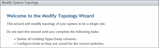
Figure 11-44 Topology wizard when switching to standard topology
Review the Summary page (Figure 11-45 on page 542) and click Finish.
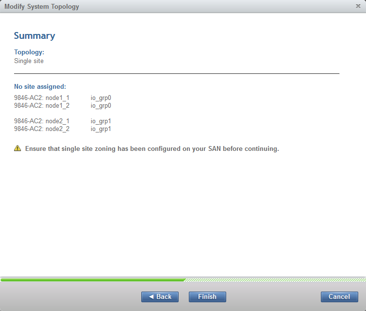
Figure 11-45 HyperSwap wizard summary when switching to standard topology
The wizard will change all controller control enclosure site attributes to nosite. You can check the status with the lssystem command (Example 11-34).
Example 11-34 The lssystem command to check system topology
lssystem
...
topology standard
...
11.13 Summary of interesting object states for HyperSwap
This section describes the state values of various commands.
11.13.1 The lsvdisk command
The status attribute shown for HyperSwap volume master VDisk in lsvdisk shows whether hosts are able to access data, for example whether the HyperSwap volume has access to up-to-date data or not, not whether the master VDisk itself is actually online. The value status for auxiliary VDisk is always offline.
Running lsvdisk on a specific VDisk to get detailed information also shows the VDisk copy status value. The RC_id and RC_name attributes for both master and auxiliary VDisks show the active-active relationship supporting the HyperSwap volume (Example 11-35).
Example 11-35 The lsvdisk command on a specific disk to see VDisk copy status
lsvdisk HS_Vol_1_Mas
...
RC_id 0
RC_name HS_Vol_1_rel
RC_change no
...
11.13.2 The lsvdiskcopy command
The status attribute for VDisk copies supporting HyperSwap volumes shows whether the underlying storage is online (Example 11-36).
Example 11-36 The lsvdiskcopy command shows if underlying storage is online
lsvdiskcopy HS_Vol_1_Mas
vdisk_id vdisk_name copy_id status sync primary mdisk_grp_id mdisk_grp_name
0 HS_Vol_1_Mas 0 online yes yes 0 mdiskgrp_west
11.13.3 The lsrcrelationship or lsrcconsistgrp commands
These values are for stand-alone relationships seen with lsrcrelationship. Relationships in a consistency group must all share the same state, primary, and freeze_time field values, so they change value based on the condition of all the relationships in that consistency group. The consistency group itself shows the same values when queried using lsrcconsistgrp. The status attribute is the key attribute that tells you the HyperSwap volume copying status:
•inconsistent_stopped
This HyperSwap volume only has useful data on the master VDisk, and the relationship’s change volumes are not both configured yet.
•consistent_stopped
This HyperSwap volume only has useful data on the master VDisk, the relationship’s change volumes are not both configured yet, but the relationship was created with -sync, limiting needed copying to only the data written to on the master VDisk since the active-active relationship was created.
•inconsistent_copying
This HyperSwap volume only has useful data on the master VDisk, but it is correctly configured and is performing initial synchronization.
•consistent_synchronized
This HyperSwap volume is correctly configured, has up-to-date data on both VDisks, and is highly available to hosts, if addvdiskaccess has been run correctly.
•consistent_copying
This HyperSwap volume is correctly configured, has had or is currently having a period of inaccessibility of one VDisk, leaving that VDisk consistent but stale (the freeze_time attribute will show when that stale data dates from). Access to that data can be provided in a disaster with the stoprcrelationship -access command, and resynchronization automatically will take place when possible.
•idling
This HyperSwap volume is correctly configured, and has had access enabled to a stale but consistent copy by running stoprcrelationship -access when the active-active relationship was in a state of consistent_copying. Synchronization is paused, and can be resumed by running startrcrelationship -primary (master | aux) according to the direction that the relationship should resynchronize in.
The primary attribute will be master or auxiliary, and tells you which copy is acting as the primary at the moment, and therefore which I/O group is primarily processing I/Os for this HyperSwap volume.
The status attribute shows online if all needed VDisks are online and are able to synchronize. Otherwise, it shows the reason why synchronization is not possible:
•primary_offline
•secondary_offline
•primary_change_offline
•secondary_change_offline
It shows one of the previous statuses if one of the VDisks of the HyperSwap volume is offline, or change_volumes_needed if the HyperSwap volume does not have both change volumes configured.
The progress attribute shows how similar the two copies are as a percentage, rounded down to the nearest percent. During resynchronization, this counts up to 100 as the HyperSwap volume nears being synchronized.
The freeze_time attribute shows at what point the data is frozen on a stale but consistent copy when the relationship has a state of consistent_copying. This enables the user to decide if there is value in using the data (with the stoprcrelationship -access command) if the up-to-date copy goes offline.
11.13.4 The lsfcmap command
The status attribute for FlashCopy mappings used by a HyperSwap volume shows if a FlashCopy mapping is currently used, for example during a resynchronization of VDisks of a HyperSwap volume after a VDisk failure.
Example 11-37 shows a FlashCopy mapping currently used during resynchronization.
Example 11-37 FlashCopy mapping currently used during resynchronization
lsfcmap fcmap1
...
name fcmap1
source_vdisk_name HS_Vol_1_Mas
target_vdisk_name HS_Vol_1_Mas_CV
status copying
progress 42
start_time 150804045444
...
11.14 Naming conventions
The reference volume can refer to a VDisk or to a HyperSwap volume depending the context.
In standard topology the reference volume is equivalent to the reference VDisk. A VDisk can be created by the mkvdisk command or the mkvolume command in standard topology.
In HyperSwap topology the reference volume is ambiguous. It should be specified as basic volume or HyperSwap volume:
•Basic volume: A volume at one site. This can be a VDisk created by the mkvdisk command or a VDisk with an mirrored copy. A basic volume is always only on one site.
•HyperSwap volume: A volume with two copies on different sites in an active-active relationship. The HyperSwap volume has one basic volume on each site.
11.15 IBM FlashSystem V9000 HyperSwap CLI commands
This section describes the CLI that applies to IBM FlashSystem V9000 Software V7.5. This section assumes that the IBM FlashSystem V9000 topology is set to HyperSwap. The commands in this section are still valid with V7.7, but the mkvolume command introduced in V7.6 is the preferred command to set up HyperSwap volumes.
IBM Knowledge Center has details about the CLI:
11.15.1 Command comparison
Table 11-8 lists the commands needed in different IBM FlashSystem V9000 software versions. In software V7.5, eight commands are necessary to create a HyperSwap volume. Starting with software 7.6, only one command is needed to create a HyperSwap volume.
Table 11-8 Creating a HyperSwap volume in different software versions
|
Creating a HyperSwap volume in V7.5
|
Creating a HyperSwap volume in V7.6 and later
|
|
mkvdisk master_vdisk
|
mkvolume my_volume
|
|
mkvdisk aux_vdisk
|
|
|
mkvdisk master_change_volume
|
|
|
mkvdisk aux_change_volume
|
|
|
mkrcrelationship –activeactive
|
|
|
chrcrelationship -masterchange
|
|
|
chrcrelationship -auxchange
|
|
|
addvdiskaccess
|
|
11.15.2 Creating HyperSwap volumes with software V7.5
HyperSwap capability enables each HyperSwap volume to be presented by two I/O groups. One VDisk on an I/O group of each site stores the data. Each of these two VDisks uses a VDisk on the same site as change volume. When the relationship between these four VDisks is defined, one VDisk is the master VDisk, the other VDisk is the auxiliary VDisk, and these two VDisks have an associated change volume. The two VDisks are kept synchronized by the IBM Spectrum Virtualize HyperSwap functions. The host sees only one HyperSwap volume. This HyperSwap volume has the LUN ID from the master VDisk.
Figure 11-46 on page 547 shows the four VDisks and the HyperSwap volume presented to the host. The host always sees a HyperSwap volume with ID 1. The VDisk with ID 2 is synchronized with the VDisk with ID 1. If the host detects a HyperSwap volume on both I/O groups, both VDisks show ID 1 to the host. The hosts multipathing driver detects and uses the preferred control enclosure for I/O.
In case of a failover, for example I/O group 1 is offline, the host accesses site 2 and uses VDisk 2, which presents ID 1 to the host. Even if internally there are different IDs, the host always sees the master ID 1. Therefore, the multipathing driver of the host can switch seamlessly to site 2.
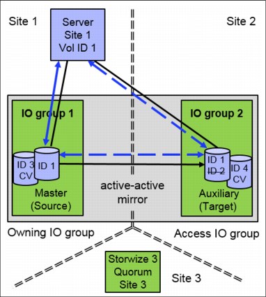
Figure 11-46 The HyperSwap volume build out of four VDisks
The four key steps to creating a HyperSwap volume are as follows:
1. Optionally, use mkrcconsistgrp to enable multiple HyperSwap volumes to copy consistently together.
2. Use mkvdisk to create the different VDisk objects required.
3. Use addvdiskaccess to enable the HyperSwap volume to be accessed on either site.
4. Use mkrcrelationship to create an active-active relationship to coordinate replication.
5. Use chrcrelationship to associate change volumes with the HyperSwap volume.
These steps are described in 11.15.3, “Creating a consistency group” on page 547 and 11.6, “Operations” on page 519.
11.15.3 Creating a consistency group
The advantages of a consistency group are described in 11.3.2, “Consistency Groups” on page 495. Creating a consistency group enables all HyperSwap volumes for a specific application to fail over together, ensuring that at least one site has an up-to-date copy of every HyperSwap volume for the application. Use the mkrcconsistgrp command to create a consistency group:
mkrcconsistgrp -name hsConsGrp0
If all HyperSwap volumes are stand-alone, this step can be omitted (if all HyperSwap volumes are fully independent and can operate individually).
11.15.4 Creating the VDisks
Four VDisks must be created for a HyperSwap volume. The master VDisk, the auxiliary VDisk, the two associated change volumes.
New master VDisk
Each HyperSwap volume needs a master VDisk. This VDisk can be created when required to hold new application data. Also possible is to use an existing VDisk, to add HyperSwap function to an existing application without affecting that application. To create a new VDisk, use the mkvdisk command:
mkvdisk -name hsVol0Mas -size 1 -unit gb -iogrp 0 -mdiskgrp mdiskgrp_site1 -accessiogrp 0:1
This will be the VDisk that holds the initial copy of the data, which is then replicated to the other site. For a completely new HyperSwap volume, it doesn’t matter which site this VDisk is created on.
|
Note: The site of the MDisk group defined by the site of the enclosure matches the site of the caching I/O group given by the -iogrp parameter. Both sites must be able to access this HyperSwap volume. Therefore, the -accessiogrp parameter must contain an I/O group of both sites.
|
The master VDisk should be mapped to all hosts on both sites that need access to the HyperSwap volume.
In this example mkvdisk command, most parameters are as normal and can be configured according to your needs. If you need the HyperSwap volume to be compressed or have particular Easy Tier characteristics, specify that here. The -accessiogrp parameter is important because it enables the HyperSwap volume to be accessed on both sites. Specify the caching I/O groups that you will use for the auxiliary VDisk, in addition to that which you have specified for the master VDisk.
By default, IBM FlashSystem V9000 VDisk is formatted with version 7.5. The speed of the formatting is controlled by the -sync parameter.
Using an existing master VDisk
If you are using an existing master VDisk, it normally has access through only its own I/O group. To enable access to the HyperSwap volume through both sites, you must add access to the HyperSwap volume through the auxiliary VDisk’s I/O group too. Use the following command:
addvdiskaccess -iogrp 1 hsVol0Mas
This part of the process is not verified, but must be completed in order for the HyperSwap volume to provide high availability through control enclosures on both sites. This step is performed for only the master VDisk.
Auxiliary VDisk
The master and auxiliary VDisks should be on similarly performing storage. If this is not possible, write performance is dictated by the slower of the two, and read performance is that of the VDisk currently acting as the primary of the HyperSwap volume.
A possibility is to use an auxiliary VDisk of a different provisioning type from the master VDisk, for example mixing a fully allocated VDisk with a thin-provisioned VDisk, or compressed and non-compressed thin-provisioned VDisks. This is not a recommended configuration. You get the performance penalty of the smaller VDisk allocation type, yet do not get all of the space benefits you could get by making both the same type. However, mixed types do work correctly, and there are conditions where it is unavoidable, for example, when starting with a compressed master VDisk, and adding an auxiliary VDisk in an I/O group without hardware compression.
A HyperSwap volume needs the master VDisk and an auxiliary VDisk. This must be the same size as the master VDisk, but using storage from the other site, and in an I/O group on the other site. To create a new auxiliary VDisk, use the mkvdisk command:
mkvdisk -name hsVol0Aux -size 1 -unit gb -iogrp 1 -mdiskgrp mdiskgrp_site2
Do not map the auxiliary VDisk to any hosts.
Change volumes
Two thin-provisioned VDisks are required to act as change volumes for this HyperSwap volume. These must be the same logical size as the master VDisk. To create the change volumes use the mkvdisk command (Example 11-38).
Example 11-38 Use the mkvdisk command to create change volumes
mkvdisk -name hsVol0MasCV -size 1 -unit gb -iogrp 0 -mdiskgrp mdiskgrp_site1 -rsize 0% -autoexpand
mkvdisk -name hsVol0AuxCV -size 1 -unit gb -iogrp 1 -mdiskgrp mdiskgrp_site2 -rsize 0% -autoexpand
One change volume is created with the same I/O group as the master VDisk, and a storage pool in the same site (not necessarily the same storage pool as the master VDisk, but using the same storage pool assures the same performance, and availability characteristics). Another change volume is created in the auxiliary VDisk’s I/O group, and a storage pool in the same site. The system does not control whether the same pool is used for a change volume as the master/auxiliary VDisk, but future versions might control this.
|
Note: Do not map the change volumes to any hosts.
|
The change volumes are used to store differences between the copies while resynchronizing the HyperSwap volume copies, and normally only require enough storage performance to satisfy the resynchronization rate. If access is enabled to the stale copy during resynchronization, as outlined in 11.7, “HyperSwap with SAS attached expansion enclosures” on page 528, a portion of host reads and writes is serviced by the change volume storage, but this decreases toward zero within a short period of time.
The change volumes normally consume capacity equal to the initially specified rsize. During resynchronization, the change volume at the stale copy grows as it retains the data needed to revert to the stale image. It grows to use the same amount of storage as the quantity of changes between the two copies.
Therefore, a stale copy that needs 20% of its data changed to be synchronized with the up-to-date copy has its change volume grow to use 20% of its logical size. After resynchronization, the change volume will automatically shrink back to the initially specified rsize.
Create the active-active relationship
This is the main step in creating a HyperSwap volume. This step adds the HyperSwap volume’s master and auxiliary VDisks to a new active-active relationship.
Active-active relationships are a special type of relationship that can only be used in HyperSwap volumes. Currently, they cannot be configured through the GUI, you cannot manually start or stop them (other than in the disaster recovery scenarios outlined in 11.7, “HyperSwap with SAS attached expansion enclosures” on page 528), and you cannot convert them into Metro Mirror or Global Mirror relationships.
If the master disk already contains application data, use the following command to create the relationship. The system name in this example is testCluster.
mkrcrelationship -master hsVol0Mas -aux hsVol0Aux -cluster testCluster -activeactive -name hsVol0Rel
At this point, the auxiliary VDisk goes offline, because from now on it is accessed internally only by the HyperSwap function. The master VDisk remains online.
If the master VDisk has not been written to yet, use the -sync parameter to avoid the initial synchronization process:
mkrcrelationship -master hsVol0Mas -aux hsVol0Aux -cluster testCluster -activeactive -name hsVol0Rel -sync
You should not use the -nofmtdisk parameter of the mkvdisk command to disable the quick initialization of fully allocated VDisk data for HyperSwap volumes. The -nofmtdisk parameter means that the two copies are different, so the -sync parameter to the mkrcrelationship command cannot be used to have HA instantly available. If it is necessary, ensure that the -sync parameter of the mkrcrelationship command is omitted so that the system fully synchronizes the two copies, even if neither has been written to.
The HyperSwap function internally joins the master and auxiliary VDisks together so that they can both be accessed through the master VDisk’s LUN ID, using whichever of the VDisks has an up-to-date copy of the data.
If you are creating many HyperSwap volumes that you want to be part of a new consistency group, you should add the active-active relationships to the group as you create them. A relationship created with a -consistgrp parameter is added into the specified consistency group when that consistency group has a state value of inconsistent_stopped (if the -sync flag was omitted), or consistent_stopped (if the -sync flag was provided).
All other relationships in that group must have been similarly created, and have not had change volumes configured yet. The following command is an example of using the -consistgrp parameter:
mkrcrelationship -master hsVol0Mas -aux hsVol0Aux -cluster testCluster -activeactive -name hsVol0Rel -consistgrp hsConsGrp0
A relationship created with a -sync flag and with a -consistgrp parameter is added into the specified consistency group if that consistency group has a state value of consistent_stopped, essentially meaning that all other relationships in that group have been similarly created, and have not had change volumes configured yet.
The following command is an example of using the -consistgrp parameter with -sync:
mkrcrelationship -master hsVol0Mas -aux hsVol0Aux -cluster testCluster -activeactive -name hsVol0Rel -consistgrp hsConsGrp0 -sync
See “Adding to a consistency group” for details about adding or removing an active-active relationship to or from a consistency group after the relationship has been created.
Adding the change volumes
You must add the two change volumes to the relationship by using the chrcrelationship command (Example 11-39).
Example 11-39 The chrcrelationship command to add two volumes to the relationship
chrcrelationship -masterchange hsVol0MasCV hsVol0Rel
chrcrelationship -auxchange hsVol0AuxCV hsVol0Rel
At this point, the active-active relationship starts replicating automatically. If the relationship was created without the -sync flag, the relationship synchronizes the existing data from the master VDisk to the auxiliary VDisk. This initial sync process does not use the change volumes.
The change volume will be used to enable automatic resynchronization after a link outage or other fault causes replication to stop.
Adding to a consistency group
Active-active relationships are added to consistency groups in just the same way as Metro Mirror and Global Mirror relationships. This can either be done when the relationship is created, as mentioned previously, or at a point after the relationship has been created using the chrcrelationship command:
chrcrelationship -consistgrp hsConsGrp0 hsVol0Rel
You cannot mix relationship types in a consistency group. When adding an active-active relationship to a consistency group, the group must either be empty or only contain active-active relationships.
You also cannot mix relationships with different states. For HyperSwap, this means that you can add a relationship to a consistency group only if the relationship has a copy in each site of the same state as the consistency group:
•The active-active relationship’s state attribute must match the active-active consistency group’s state attribute.
•If the state is not consistent_synchronized, the site of the VDisk acting as the primary copy of the active-active relationship must be the same as the site of the VDisks acting as the primary copies of the relationships in the active-active consistency group. Further details about active-active relationship replication direction are in 11.6, “Operations” on page 519.
•If the state is consistent_synchronized, and the site of the primary VDisk of the active-active relationship is not the same as the primary site of the consistency group, the relationship has its direction switched as it is added so that the primary site matches.
•If the site of the master VDisk of the active-active relationship does not match the site of the master VDisks of the relationships in the consistency group, the role of the master and auxiliary VDisks in the active-active relationship are swapped. Host access continues to be provided through the same VDisk ID and host maps, which are now the auxiliary VDisk of the relationship.
The relationship ID is retained even though this now matches the auxiliary VDisk ID.
The master and auxiliary roles are restored if the relationship is removed from the consistency group.
The master and auxiliary roles are restored if the relationship is removed from the consistency group.
If you need to remove that HyperSwap volume from the consistency group, so that it can fail over independently, use the chrcrelationship command:
chrcrelationship -noconsistgrp hsVol0Rel
11.15.5 HyperSwap V7.5 setup
This section shows examples of configuring FlashSystem V9000 HyperSwap for HyperSwap setup and HyperSwap volume setup, and includes the following tasks:
1. HyperSwap setup:
a. Define the sites.
b. Configure the control enclosures.
c. Configure the FlashSystem V9000 storage enclosures.
d. Configure the storage controllers and quorum disk.
e. Configure the hosts.
f. Configure the HyperSwap topology.
g. Configure synchronization rates.
2. HyperSwap volume setup:
a. Set up the master VDisk.
b. Set up the auxiliary VDisk.
c. Set up the relationship and change volumes.
d. Add to a consistency group.
e. Map HyperSwap volumes to the host.
Example 11-40 shows the configuring of IBM FlashSystem V9000 HyperSwap. The command output shown here is shortened for better readability.
Example 11-40 HyperSwap Setup Example
# Define the sites
IBM_FlashSystem:TestCluster:superuser>lssite
ID site_name
1 site1
2 site2
3 site3
IBM_FlashSystem:TestCluster:superuser>chsite -?
chsite
Syntax
>>-chsite-- -- -name--new_ site_name-- ------------------------->
>--+-site_id------------+--------------------------------------><
'-existing_site_name-'
IBM_FlashSystem:TestCluster:superuser>chsite -name datacenter_west 1
IBM_FlashSystem:TestCluster:superuser>chsite -name datacenter_east 2
IBM_FlashSystem:TestCluster:superuser>chsite -name quorum_site 3
IBM_FlashSystem:TestCluster:superuser>lssite
ID site_name
1 datacenter_west
2 datacenter_east
3 quorum_site
# Configure the control enclosures
IBM_FlashSystem:TestCluster:superuser>lsnode
ID name site_id site_name
1 node1
2 node_78AV610
3 node_75AD820
4 node_75AD830
IBM_FlashSystem:TestCluster:superuser>chnode -?
chnode
Syntax
>>- chnode -- | chnodecanister -- ------------------------------>
>--+--------------------------+-- --+- object_id ---+----------><
+- -site --+- site_id ---+-+ '- object_name -'
| '- site_name -' |
'- -nosite ----------------'
IBM_FlashSystem:TestCluster:superuser>chnode -site datacenter_west node1
IBM_FlashSystem:TestCluster:superuser>chnode -site datacenter_west node_78AV610
IBM_FlashSystem:TestCluster:superuser>chnode -site datacenter_east node_75AD820
IBM_FlashSystem:TestCluster:superuser>chnode -site datacenter_east node_75AD830
IBM_FlashSystem:TestCluster:superuser>lsnode
id name site_id site_name
1 node1 1 datacenter_west
2 node_78AV610 1 datacenter_west
3 node_75AD820 2 datacenter_east
4 node_75AD830 2 datacenter_east
# Configure the FlashSystem V9000 storage enclosures
IBM_FlashSystem:TestCluster:superuser>lsenclosure
id status type site_id site_name
1 online expansion
2 online expansion
IBM_FlashSystem:TestCluster:superuser>chenclosure -?
chenclosure
Syntax
>>- chenclosure --+- -identify --yes | no-+-- -- -- ------------>
+- -managed --+-yes-+---+
'-no--'
>--+--------------------------+-- -id --enclosure_id-----------><
+- -site --+- site_name -+-+
| '- site_id ---' |
'- -nosite ----------------'
IBM_FlashSystem:TestCluster:superuser>chenclosure -site datacenter_west 1
IBM_FlashSystem:TestCluster:superuser>chenclosure -site datacenter_east 2
IBM_FlashSystem:TestCluster:superuser>lsenclosure
ID status type site_id site_name
1 online expansion 1 datacenter_west
2 online expansion 2 datacenter_east
# Configure the storage controllers
IBM_FlashSystem:TestCluster:superuser>lscontroller
ID controller_name site_id site_name
4 controller0
5 controller1
IBM_FlashSystem:TestCluster:superuser>chcontroller -?
chcontroller
Syntax
>>- chcontroller -- --+---------------------+-- ---------------->
'- -name -- new_name -'
>--+-------------------------+--+--------------------------+---->
'- -allowquorum --+-yes-+-' +- -site --+- site_name -+-+
'-no--' | '- site_id ---' |
'- -nosite ----------------'
>--+- controller_id ---+---------------------------------------><
'- controller_name -'
IBM_FlashSystem:TestCluster:superuser>chcontroller -site quorum_site 4
IBM_FlashSystem:TestCluster:superuser>lscontroller
id controller_name site_id site_name
4 controller0 3 quorum_site
5 controller1 3 quorum_site
# Configure quorum disk
#One quorum disk on each site, active quorum disk on third site
IBM_FlashSystem:TestCluster:superuser>lsquorum
quorum_index status id name controller_id active object_type site_id site_name
0 online 2 no mdisk 3 datacenter_west
1 online 23 no drive 2 datacenter_east
2 online 11 yes drive 1 datacenter_west
IBM_FlashSystem:TestCluster:superuser>chquorum -?
chquorum
Syntax
>>- chquorum -- --+-----------+-- ------------------------------>
'- -active -'
>--+--------------------------+-- --+---------------------+----->
+- -mdisk --+-mdisk_id---+-+ '- -override --yes|no-'
| '-mdisk_name-' |
'- -drive -- drive_id -----'
>-- -- quorum_id ----------------------------------------------><
IBM_FlashSystem:TestCluster:superuser>chquorum -active -mdisk mdisk4 -override yes 0
IBM_FlashSystem:TestCluster:superuser>lsquorum
quorum_index status ID name controller_id active object_type site_id site_name
0 online 4 mdisk4 4 yes mdisk 3 quorum_site
1 online 23 no drive 2 datacenter_east
2 online 11 no drive 1 datacenter_west
# Configure the hosts
IBM_FlashSystem:TestCluster:superuser>lshost
ID name port_count iogrp_count status site_id site_name
0 Windows_1 4 4 online
IBM_FlashSystem:TestCluster:superuser>chhost -?
chhost
Syntax
>>- chhost -- --+----------------------------+------------------>
>--+--------------------------+--+- host_name -+---------------><
+- -site --+- site_name -+-+ '- host_id ---'
| '- site_id ---' |
'- -nosite ----------------'
IBM_FlashSystem:TestCluster:superuser>chhost -site datacenter_west 0
IBM_FlashSystem:TestCluster:superuser>lshost
ID name port_count iogrp_count status site_id site_name
0 Windows_1 4 4 online 1 datacenter_west
# Configure the HyperSwap topology
IBM_FlashSystem:TestCluster:superuser>lssystem
. . .
topology standard
topology_status
. . .
IBM_FlashSystem:TestCluster:superuser>chsystem -?
chsystem
Syntax
>>- chsystem -- -- --+------------------------+-- -------------->
'- -name -- system_name -'
>--+----------------------------+-- ---------------------------->
'- -topology --+-standard--+-'
'-hyperswap-'
BM_FlashSystem:TestCluster:superuser>chsystem -topology hyperswap
IBM_FlashSystem:TestCluster:superuser>lssystem | grep topo
. . .
topology hyperswap
topology_status dual_site
. . .
# Configure synchronization rates
# 8000 mbits total (writes and synchronization), maximal 50 % synchronization
IBM_FlashSystem:TestCluster:superuser>lspartnership
ID name location partnership type cluster_ip event_log_sequence
000002032060460E TestCluster local
IBM_FlashSystem:TestCluster:superuser>lspartnership 000002032060460E
. . .
link_bandwidth_mbits 200
background_copy_rate 100
IBM_FlashSystem:TestCluster:superuser>chpartnership -?
chpartnership
Syntax
>>- chpartnership -- --+- -start -+-- -------------------------->
>-- --+-------------------------------------+-- -- ------------->
'- -backgroundcopyrate -- percentage -'
>--+-------------------------------------------------+-- ------->
'- -linkbandwidthmbits -- link_bandwidth_in_mbps -'
>--+- remote_cluster_id ---+-----------------------------------><
'- remote_cluster_name -'
IBM_FlashSystem:TestCluster:superuser>chpartnership -linkbandwidthmbits 8000 -backgroundcopyrate 50 TestCluster
IBM_FlashSystem:TestCluster:superuser>lspartnership 000002032060460E
link_bandwidth_mbits 8000
background_copy_rate 50
BM_FlashSystem:TestCluster:superuser>lssystem
relationship_bandwidth_limit 25
IBM_FlashSystem:TestCluster:superuser>chsystem -?
chsystem
Syntax
>>- chsystem -- -- --+------------------------+-- -------------->
'- -name -- system_name -'
>--+----------------------------------------------------+-- ---->
'- -relationshipbandwidthlimit -- bandwidth_in_mBps -'
# Maximal 200 MB relationship bandwidth for a vdisk
IBM_FlashSystem:TestCluster:superuser>chsystem -relationshipbandwidthlimit 200
IBM_FlashSystem:TestCluster:superuser>lssystem
relationship_bandwidth_limit 200
IBM_FlashSystem:TestCluster:superuser>
Example 11-41 shows the configuring of IBM FlashSystem V9000 HyperSwap volumes. Two HyperSwap volumes are created. In total, eight VDisks and two active-active relationships are used. The command output is shortened for better readability.
Example 11-41 HyperSwap Volume example
# Check the sites of the pools
IBM_FlashSystem:TestCluster:superuser>lsmdiskgrp
id name status site_id site_name
0 mdiskgrp_west online 1 datacenter_west
1 mdiskgrp_east online 2 datacenter_east
2 mdiskgrp_quorum online 3 quorum_site
# Master Vdisk and associated Change Volume
mkvdisk -name HS_Vol_1_Mas -size 34 -unit gb -iogrp 0 -mdiskgrp mdiskgrp_west -accessiogrp 0:1 -syncrate 100
mkvdisk -name HS_Vol_1_Mas_CV -size 34 -unit gb -iogrp 0 -mdiskgrp mdiskgrp_west -rsize 0% -autoexpand
# Auxiliary Vdisk and associated Change Volume
mkvdisk -name HS_Vol_1_Aux -size 34 -unit gb -iogrp 1 -mdiskgrp mdiskgrp_east -syncrate 100
mkvdisk -name HS_Vol_1_Aux_CV -size 34 -unit gb -iogrp 1 -mdiskgrp mdiskgrp_east -rsize 0% -autoexpand
# Relationship master, auxiliary, and change volumes
mkrcrelationship -master HS_Vol_1_Mas -aux HS_Vol_1_Aux -cluster TestCluster -activeactive -name HS_Vol_1_rel
chrcrelationship -masterchange HS_Vol_1_Mas_CV HS_Vol_1_rel
chrcrelationship -auxchange HS_Vol_1_Aux_CV HS_Vol_1_rel
# Check the HyperSwap volume, all four vdisks and the relationship are created
IBM_FlashSystem:TestCluster:superuser>lsvdisk
id name IO_group_name status mdisk_grp_name capacity RC_name
0 HS_Vol_1_Mas io_grp0 online mdiskgrp_west 34.00GB HS_Vol_1_rel
1 HS_Vol_1_Mas_CV io_grp0 online mdiskgrp_west 34.00GB HS_Vol_1_rel
2 HS_Vol_1_Aux io_grp1 offline mdiskgrp_east 34.00GB HS_Vol_1_rel
3 HS_Vol_1_Aux_CV io_grp1 online mdiskgrp_east 34.00GB HS_Vol_1_rel
IBM_FlashSystem:TestCluster:superuser>lsrcrelationship HS_Vol_1_rel
id 0
name HS_Vol_1_rel
master_cluster_id 000002032060460E
master_cluster_name TestCluster
master_vdisk_id 0
master_vdisk_name HS_Vol_1_Mas
aux_cluster_id 000002032060460E
aux_cluster_name TestCluster
aux_vdisk_id 2
aux_vdisk_name HS_Vol_1_Aux
primary master
consistency_group_id
consistency_group_name
state consistent_synchronized
bg_copy_priority 50
progress
freeze_time
status online
sync
copy_type activeactive
cycling_mode
cycle_period_seconds 300
master_change_vdisk_id 1
master_change_vdisk_name HS_Vol_1_Mas_CV
aux_change_vdisk_id 3
aux_change_vdisk_name HS_Vol_1_Aux_CV
# second HyperSwap volume
mkvdisk -name HS_Vol_2_Mas -size 35 -unit gb -iogrp 0 -mdiskgrp mdiskgrp_west -accessiogrp 0:1 -syncrate 100
mkvdisk -name HS_Vol_2_Mas_CV -size 35 -unit gb -iogrp 0 -mdiskgrp mdiskgrp_west -rsize 0% -autoexpand
mkvdisk -name HS_Vol_2_Aux -size 35 -unit gb -iogrp 1 -mdiskgrp mdiskgrp_east -syncrate 100
mkvdisk -name HS_Vol_2_Aux_CV -size 35 -unit gb -iogrp 1 -mdiskgrp mdiskgrp_east -rsize 0% -autoexpand
mkrcrelationship -master HS_Vol_2_Mas -aux HS_Vol_2_Aux -cluster TestCluster -activeactive -name HS_Vol_2_rel
chrcrelationship -masterchange HS_Vol_2_Mas_CV HS_Vol_2_rel
chrcrelationship -auxchange HS_Vol_2_Aux_CV HS_Vol_2_rel
IBM_FlashSystem:TestCluster:superuser>lsvdisk
id name IO_group_name status mdisk_grp_id mdisk_grp_name capacity type RC_id RC_name
0 HS_Vol_1_Mas io_grp0 online 0 mdiskgrp_west 34.00GB striped 0 HS_Vol_1_rel
1 HS_Vol_1_Mas_CV io_grp0 online 0 mdiskgrp_west 34.00GB striped 0 HS_Vol_1_rel
2 HS_Vol_1_Aux io_grp1 offline 1 mdiskgrp_east 34.00GB striped 0 HS_Vol_1_rel
3 HS_Vol_1_Aux_CV io_grp1 online 1 mdiskgrp_east 34.00GB striped 0 HS_Vol_1_rel
6 HS_Vol_2_Mas io_grp0 online 0 mdiskgrp_west 35.00GB striped 6 HS_Vol_2_rel
7 HS_Vol_2_Mas_CV io_grp0 online 0 mdiskgrp_west 35.00GB striped 6 HS_Vol_2_rel
8 HS_Vol_2_Aux io_grp1 offline 1 mdiskgrp_east 35.00GB striped 6 HS_Vol_2_rel
9 HS_Vol_2_Aux_CV io_grp1 online 1 mdiskgrp_east 35.00GB striped 6 HS_Vol_2_rel
# Adding to a consistency Group
# Create the consistency group
IBM_FlashSystem:TestCluster:superuser>mkrcconsistgrp -name HS_ConsGrp_0
RC Consistency Group, id [0], successfully created
# Add HyperSwap volumes, the active-active relationsship to the consistency group
IBM_FlashSystem:TestCluster:superuser>chrcrelationship -consistgrp HS_ConsGrp_0 HS_Vol_1_rel
IBM_FlashSystem:TestCluster:superuser>chrcrelationship -consistgrp HS_ConsGrp_0 HS_Vol_2_rel
IBM_FlashSystem:TestCluster:superuser>lsrcconsistgrp HS_ConsGrp_0
id 0
name HS_ConsGrp_0
master_cluster_id 000002032060460E
master_cluster_name TestCluster
aux_cluster_id 000002032060460E
aux_cluster_name TestCluster
primary master
state consistent_synchronized
relationship_count 2
freeze_time
status
sync
copy_type activeactive
cycling_mode
cycle_period_seconds 300
RC_rel_id 0
RC_rel_name HS_Vol_1_rel
RC_rel_id 6
RC_rel_name HS_Vol_2_rel
# Map HyperSwap volumes to host
IBM_FlashSystem:TestCluster:superuser>mkvdiskhostmap -host Windows_1 HS_Vol_1_Mas
Virtual Disk to Host map, id [0], successfully created
IBM_FlashSystem:TestCluster:superuser>mkvdiskhostmap -host Windows_1 HS_Vol_2_Mas
Virtual Disk to Host map, id [1], successfully created
IBM FlashSystem V9000 HyperSwap is created and two HyperSwap volumes are mapped to a host. The next step is to configure the host. Examples of configuring hosts on various supported operating systems are in Chapter 7, “Host configuration” on page 255.
11.15.6 Converting to basic volumes, while retaining access through the
auxiliary VDisk
auxiliary VDisk
If you need to retain the auxiliary VDisk, two possible procedures are available:
•Deleting the master disk using the rmvdisk command
•Deleting the master disk using the rmvdisk -keepaux command and parameter
Deleting the master disk using rmvdisk
First, you must quiesce any host using this HyperSwap volume. By deleting the master VDisk and the two change volumes, the active-active relationship is automatically deleted, and only the auxiliary VDisk remains. Host maps are deleted as the master VDisk is deleted, and new host maps must be created from the remaining auxiliary VDisk. Use the rmvdisk command. The -force parameter is needed for the master VDisk (Example 11-42).
Example 11-42 rmvdisk command to delete the master VDisk and two change volumes
rmvdisk -force hsVol0Mas
rmvdisk hsVol0MasCV
rmvdisk hsVol0AuxCV
The host accesses the data on the auxiliary VDisk, so it should normally be done only if the auxiliary copy is up-to-date. This can be seen by the active-active relationship either having a primary value of master, or a state value of consistent_synchronized.
You must remap these auxiliary VDisks to the host systems because the existing HyperSwap volume host maps were deleted with the master VDisks, so the VDisks are seen with new unique LUN IDs.
Finally, you can redetect volumes on the host systems, reconfigure them to use the auxiliary VDisks for I/O, and then resume host I/O.
Deleting the master disk using rmvdisk -keepaux
An alternative procedure is to delete the master VDisk with the following command:
rmvdisk -force -keepaux <mastervdisk>
This command can be run with host I/O running. It deletes the master VDisk’s storage and replaces it with the auxiliary VDisk’s storage, preserving the master VDisk ID, the master VDisk host maps, and the auxiliary VDisk storage. It also deletes the active-active relationship. Finally, delete the change volumes (Example 11-43), which are not deleted as part of the previous step.
Example 11-43 The rmvdisk command to delete change volumes
rmvdisk hsVol0MasCV
rmvdisk hsVol0AuxCV
This enables a clean-up of failed master storage without affecting host I/O access, potentially as part of replacing the master VDisk’s storage.
..................Content has been hidden....................
You can't read the all page of ebook, please click here login for view all page.