

Planning
This chapter describes the steps that are required when you plan the installation of the IBM FlashSystem V9000 in your environment. This chapter considers the implications of your storage network from both the host attachment side and the internal storage expansion side. This chapter also describes all the environmental requirements that you must consider.
This chapter includes the following topics:
4.1 General planning introduction
To achieve the most benefit from the IBM FlashSystem V9000, preinstallation planning must include several important steps. These steps can ensure that the IBM FlashSystem V9000 provides the best possible performance, reliability, and ease of management to meet the needs of your solution. Proper planning and configuration also helps minimize future downtime by avoiding the need for changes to the IBM FlashSystem V9000 and the storage area network (SAN) environment to meet future growth needs.
Important steps include planning the IBM FlashSystem V9000 configuration and completing the planning tasks and worksheets before system installation.
An IBM FlashSystem V9000 solution is sold in what is referred to as a building block, as shown in Figure 4-1. A single building block consists of two AC2 or AC3 control enclosures and one AE2 expansion. Each building block is an I/O Group in the solution.
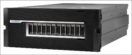
Figure 4-1 IBM FlashSystem V9000 base building block
IBM FlashSystem V9000 can be grown in two directions depending on the needs of the environment. This is known as the scale-up, scale-out capability:
•It can have all its capabilities increased by adding up to four total building blocks to the solution. This increases both the capacity and the performance alike.
•If just capacity is needed, it can be increased by adding up to four total AE2 storage enclosures beyond the single AE2 contained within each building block.
A fully configured IBM FlashSystem V9000 consists of eight AC2 or AC3 control enclosures and eight AE2 storage enclosures, sometimes referred to as an eight by eight configuration.
This chapter covers planning for the installation of a single IBM FlashSystem V9000 solution, consisting of a single building block (two AC2 or AC3 control enclosures and one AE2 storage enclosure). When you plan for larger IBM FlashSystem V9000 configurations, consider the required SAN and networking connections for the appropriate number of building blocks and scale-up expansion AE2 storage controllers.
For details about scalability and multiple building blocks, see Chapter 5, “Scalability” on page 179.
|
Requirement: A pre-sale Technical Delivery Assessment (TDA) must be conducted to ensure that the configuration is correct and the solution being planned for is valid. A pre-install TDA must be conducted shortly after the order is placed and before the equipment arrives at the customer’s location to ensure that the site is ready for the delivery and that roles and responsibilities are documented regarding all the parties who will be engaged during the installation and implementation. Before the system is installed and configured, you must complete all the planning worksheets. When the planning worksheets are completed, you submit them to the IBM service support representative (SSR).
|
Follow these steps when you plan for an IBM FlashSystem V9000 solution:
1. Collect and document the number of hosts (application servers) to attach to the IBM FlashSystem V9000, the traffic profile activity (read or write, sequential, or random), and the performance expectations for each user group (input/output (I/O) operations per second (IOPS) and throughput in megabytes per second (MBps)).
2. Collect and document the storage requirements and capacities:
– Total internal expansion capacity that will exist in the environment.
– Total external storage that will be attached to the IBM FlashSystem V9000.
– Required storage capacity for local mirror copy (Volume mirroring).
– Required storage capacity for point-in-time copy (IBM FlashCopy).
– Required storage capacity for remote copy (Metro Mirror and Global Mirror).
– Required storage capacity for use of the IBM HyperSwap function.
– Required storage capacity for compressed volumes.
– Per host for storage capacity, the host logical unit number (LUN) quantity, and sizes.
– Required virtual storage capacity that is used as a fully managed volume and used as a thin-provisioned volume.
3. Define the local and remote IBM FlashSystem V9000 SAN fabrics to be used for both the internal connections and the host and external storage. Also plan for the remote copy or the secondary disaster recovery site as needed.
4. Define the number of building blocks and additional expansion AE2 storage controllers required for the site solution. Each building block that makes up an I/O Group is the container for the volume. The number of necessary I/O Groups depends on the overall performance requirements.
5. Design the host side of the SAN according to the requirements for high availability and best performance. Consider the total number of ports and the bandwidth that is needed between the host and the IBM FlashSystem V9000, and the IBM FlashSystem V9000 and the external storage subsystems.
6. Design the internal side of the SAN according to the requirements as outlined in the cabling specifications for the building blocks being installed. This SAN network is used for IBM FlashSystem V9000 control nodes, and the expansion storage data transfers. Connecting this network across inter-switch links (ISL) is not supported.
|
Important: Check and carefully count the required ports for the wanted configuration. Equally important, consider future expansion when planning an initial installation to ensure ease of growth.
|
7. If your solution uses Internet Small Computer System Interface (iSCSI), design the iSCSI network according to the requirements for high availability (HA) and best performance. Consider the total number of ports and bandwidth that is needed between the host and the IBM FlashSystem V9000.
8. Determine the IBM FlashSystem V9000 cluster management and AC2 or AC3 service Internet Protocol (IP) addresses needed. The system requires an IP address for the cluster and each of the AC2 or AC3 control enclosures.
9. Determine the IP addresses for the IBM FlashSystem V9000 system and for the hosts that connect through the iSCSI network.
10. Define a naming convention for the IBM FlashSystem V9000 AC2 or AC3 control enclosures, host, and any external storage subsystem planned. For example, ITSO_V9000-1 shows that the IBM FlashSystem V9000 is mainly used by the International Technical Support Organization (ITSO) Redbooks team, and is the first IBM FlashSystem V9000 in the department.
11. Define the managed disks (MDisks) from external storage subsystems.
12. If needed, define storage pools. The use of storage pools depend on the workload, any external storage subsystem connected, more expansions or building blocks being added, and the focus for their use. There might also be a need for defining pools for use by data migration requirements or easy tier.
13. Plan the logical configuration of the volumes within the I/O Groups and the storage pools to optimize the I/O load between the hosts and the IBM FlashSystem V9000.
14. Plan for the physical location of the equipment in the rack. IBM FlashSystem V9000 planning can be categorized into two types:
– Physical planning
– Logical planning
The following sections describe these planning types in more detail.
|
Note: IBM FlashSystem V9000 V7.7.1 and later provides GUI management of the HyperSwap function. HyperSwap enables each volume to be presented by two I/O groups. If you plan to use this function, you must consider the I/O Group assignments in the planning for the IBM FlashSystem V9000.
|
For more details about the HyperSwap function, see Chapter 2, “FlashSystem V9000 architecture” on page 25, and Chapter 11, “IBM HyperSwap” on page 485.
4.2 Physical planning
Use the information in this section as guidance when you are planning the physical layout and connections to use for installing your IBM FlashSystem V9000 in a rack and connecting to your environment.
Industry standard racks are defined by the Electronic Industries Alliance (EIA) as 19-inch wide by 1.75-inch tall rack spaces or units, each of which is commonly referred to as 1U of the rack. Each IBM FlashSystem V9000 building block requires 6U of contiguous space in a standard rack. Additionally, each add-on expansion enclosure requires another 2U of space.
When growing the IBM FlashSystem V9000 solution by adding building blocks and expansions, the best approach is to plan for all of the members to be installed in the same cabinet for ease of cabling the internal dedicated SAN fabric connections. One 42U rack cabinet can house an entire maximum configuration of an IBM FlashSystem V9000 solution, and also its SAN switches and an Ethernet switch for management connections.
Figure 4-2 shows a fully configured solution of four building blocks in a 42U rack.
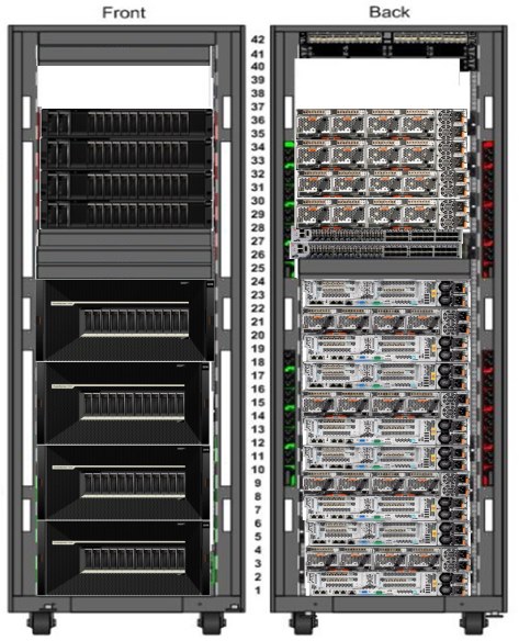
Figure 4-2 Maximum future configuration of IBM FlashSystemV9000 fully scaled-out and scaled-up
The AC2 control enclosures
Each AC2 control enclosure can support up to six PCIe expansion I/O cards, as identified in Table 4-1, to provide a range of connectivity and capacity expansion options.
Table 4-1 Layout of expansion card options for AC2 control enclosures
|
Top of control enclosure cards supported
|
|
|
PCIe Slot 1: I/O Card (8 gigabit (Gb) or 16 Gb Fibre Channel (FC))
|
PCIe Slot 4: Compression Acceleration Card
|
|
PCIe Slot 2: I/O Card (8 Gb,16 Gb FC, or
10 gigabyte Ethernet (GbE)) |
PCIe Slot 5: I/O Card (8 Gb,16 Gb FC, or
10 GbE) |
|
PCIe Slot 3: I/O (16 Gb FC only)
|
PCIe Slot 6: Compression Acceleration Card
|
The AC3 control enclosures
Each AC3 control enclosure can support up to eight PCIe expansion I/O cards, as identified in Table 4-2, to provide a range of connectivity and capacity expansion options.
Table 4-2 Layout of expansion card options for AC3 control enclosures
|
PCIe slot
|
Adapter Type
|
|
1
|
Not supported for use
|
|
2
|
SAS
|
|
3
|
Fibre Channel or Ethernet
|
|
4
|
Fibre Channel or Ethernet
|
|
5
|
SAS or Compression accelerator
|
|
6
|
Fibre Channel or Ethernet
|
|
7
|
Fibre Channel or Ethernet
|
|
8
|
Compression Accelerator
|
Five I/O adapter options can be ordered:
•Feature code AH10: Four-port 8 gigabits per second (Gbps) FC Card:
– Includes one four-port 8 Gbps FC Card with four Shortwave Transceivers.
– Maximum feature quantity is three.
•Feature code AH11: Two-port 16 Gbps FC Card:
– Includes one two-port 16 Gbps FC Card with two Shortwave Transceivers.
– Maximum feature quantity is four.
•Feature code AH12: 4-port 10 Gbps Ethernet (iSCSI/FCoE):
– Includes one four-port 10 GbE Card with four small form-factor pluggable plus (SFP+) transceivers.
– Maximum feature quantity is one.
•Feature code AH13: 4-port 12 Gbps SAS
•Feature code AF44: 4-port 16 Gbps Fibre Channel
There is also an option for ordering the compression accelerator feature, which is included by default with IBM Real-time Compression software:
•Feature code AH1A: Compression Acceleration Card:
– Includes one Compression Acceleration Card.
– Maximum feature quantity is two.
Note the following information about the AC3 control enclosure PCIe adapters and slots:
•A maximum of four 4-port 16 Gbps Fibre Channel adapters can be installed in each control enclosure.
•A maximum of one 4-port 10 Gbs Ethernet (iSCSI/FCoE) adapter can be installed in each control enclosure.
•The 4-port SAS adapter can connect to V9000 standard or high-density expansion enclosures only. Only ports 1 and 3 can be used to provide the connections to each of the expansion enclosures.
•The compression accelerator adapter has no external ports. Compression adapters can be installed in PCIe slots 5 and 8 only. Two adapters can be installed offering improved I/O performance when using compressed volumes.
For more IBM FlashSystem product details, see IBM FlashSystem V9000 Version 7.7 Product Guide, REDP-5409.
Figure 4-3 shows the rear view of an AC2 control enclosure with the six available Peripheral Component Interconnect Express (PCIe) adapter slots locations identified.
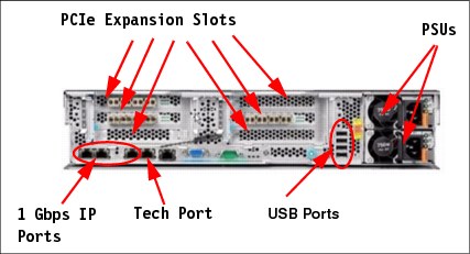
Figure 4-3 AC2 rear view
Figure 4-4 shows the rear view of an AC3 control enclosure with the eight available PCIe adapter slots locations identified.
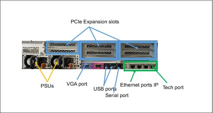
Figure 4-4 AC3 control enclosure rear view
The AE2 storage enclosure is a flash memory enclosure that can house up to 12 modules of 1.2 TB, 2.9 TB, and 5.7 TB capacities. The enclosure is equipped with either four FC adapters configured with four 8 Gbps ports, or configured with two 16 Gbps ports. There are two adapters per canister for a total of sixteen or eight ports. The AE2 storage enclosure also has two redundant 1300 W power supplies.
Figure 4-5 shows locations of these components. In normal circumstances, the 1 Gbps Ethernet ports and Universal Serial Bus (USB) ports are not used in this enclosure.
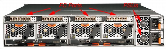
Figure 4-5 AE2 view
4.2.1 Racking considerations
IBM FlashSystem V9000 must be installed in a minimum of a one building block configuration. Each building block is designed with the two AC2 or AC3 control enclosures and the AE2 enclosure in the middle. These enclosures must be installed contiguously and in the proper order for the system bezel to be attached to the front of the system. A total of 6U is needed for a single building block. Ensure that the space for the entire system is available.
Location of IBM FlashSystem V9000 in the rack
Because the IBM FlashSystem V9000 AC2 or AC3 control enclosures and AE2 storage enclosure must be racked together behind their front bezel, all the members of the IBM FlashSystem V9000 must be interconnected together; the location where you rack the AC2 or AC3 and the AE2 enclosures is important.
Use Table 4-3 to help plan the rack locations that you use for up to a 42U rack. Complete the table for the hardware locations of the IBM FlashSystem V9000 system and other devices.
Table 4-3 Hardware location planning of the IBM FlashSystem V9000 in the rack
|
Rack unit
|
Component
|
|
EIA 42
|
|
|
EIA 41
|
|
|
EIA 40
|
|
|
EIA 39
|
|
|
EIA 38
|
|
|
EIA 37
|
|
|
EIA 36
|
|
|
EIA 35
|
|
|
EIA 34
|
|
|
EIA 33
|
|
|
EIA 32
|
|
|
EIA 31
|
|
|
EIA 30
|
|
|
EIA 29
|
|
|
EIA 28
|
|
|
EIA 27
|
|
|
EIA 26
|
|
|
EIA 25
|
|
|
EIA 24
|
|
|
EIA 23
|
|
|
EIA 22
|
|
|
EIA 21
|
|
|
EIA 20
|
|
|
EIA 19
|
|
|
EIA 18
|
|
|
EIA 17
|
|
|
EIA 16
|
|
|
EIA 15
|
|
|
EIA 14
|
|
|
EIA 13
|
|
|
EIA 12
|
|
|
EIA 11
|
|
|
EIA 10
|
|
|
EIA 9
|
|
|
EIA 8
|
|
|
EIA 7
|
|
|
EIA 6
|
|
|
EIA 5
|
|
|
EIA 4
|
|
|
EIA 3
|
|
|
EIA 2
|
|
|
EIA 1
|
|
Figure 4-6 shows a single base building block IBM FlashSystem V9000 rack installation with space for future growth.
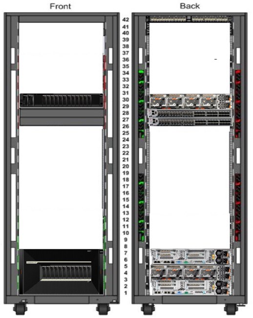
Figure 4-6 Sample racking of an IBM FlashSystemV9000 single building block with an add-on expansion for capacity
4.2.2 Power requirements
Each AC2 or AC3 and AE2 enclosures requires two IEC-C13 power cable connections to connect to their 750 W and 1300 W power supplies. Country specifics power cables are available for ordering to ensure that proper cabling is provided for the specific region. A total of six power cords are required to connect the IBM FlashSystem V9000 building block to power.
Figure 4-7 shows an example of a base building block with the two AC2s, with two 750-W power supplies in each, and the AE2 with two 1300-W power supplies. There are six connections that require power for the IBM FlashSystem V9000 system.
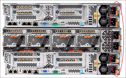
Figure 4-7 IBM FlashSystemV9000 fixed building block power cable connections
Figure 4-8 shows the rear view of the AC3 control enclosure with two redundant power supplies.
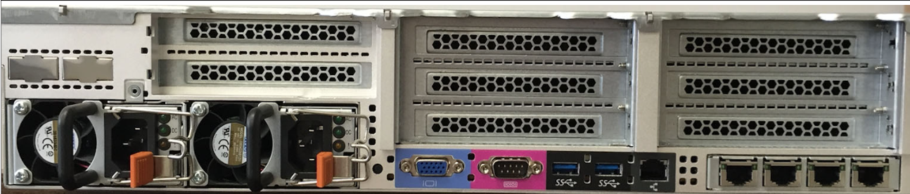
Figure 4-8 AC3 control enclosure rear view.
Upstream redundancy of the power to your cabinet (power circuit panels and on-floor Power Distribution Units (PDUs)) and within cabinet power redundancy (dual power strips or in-cabinet PDUs) and also upstream high availability structures (uninterruptible power supply (UPS), generators, and so on) influences your power cabling decisions.
If you are designing an initial layout that will have future growth plans to follow, you should plan to allow for the additional building blocks to be co-located in the same rack with your initial system for ease of planning for the additional interconnects required. A maximum configuration of the IBM FlashSystem V9000 with dedicated internal switches for SAN and local area network (LAN) can almost fill a 42U 19-inch rack.
Figure 4-6 on page 144 shows a single 42U rack cabinet implementation of a base building block IBM FlashSystem V9000 and also one optional IBM FlashSystem V9000 AE2 expansion add-on, all racked with SAN and LAN switches capable of handling additional future scaled out, scaled up additions with the 16 Gb switches for the SAN.
|
Tip: When cabling the power, connect one power cable from each AC2 or AC3 control enclosures and AE2 storage enclosure to the left side internal PDU and the other power supply power cable to the right side internal PDU. This enables the cabinet to be split between two independent power sources for greater availability. When adding more IBM FlashSystem V9000 building blocks to the solution, continue the same power cabling scheme for each additional enclosure.
|
You must consider the maximum power rating of the rack: do not exceed it. For more power requirement information, see IBM FlashSystem V9000 at IBM Knowledge Center:
4.2.3 Network cable connections
As shown in Figure 4-9, the FC ports for this example (an 8 Gbps fixed building block) are identified for all the connections of the internal (back-end) fiber connections.
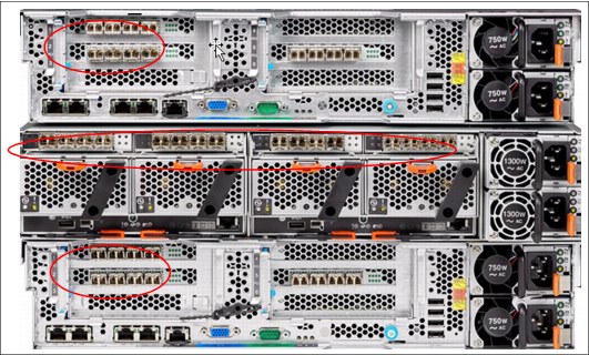
Figure 4-9 IBM FlashSystemV9000 fixed building block 8 Gbps FC cable connections
Create a cable connection table or similar documentation to track all of the connections that are required for the setup of these items:
•AC2 or AC3 controller enclosures
•AE2 storage enclosures
•Ethernet
•FC ports: Host and internal
•iSCSI and Fibre Channel over Ethernet (FCoE) connections
Figure 4-10 shows the back of the AC3 control enclosure with PCIe slots information.
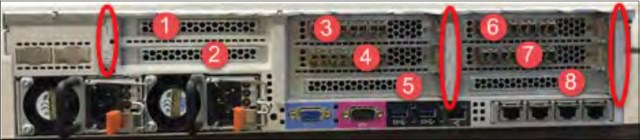
Figure 4-10 AC3 control enclosure rear view with PCIe slots information
Slot numbers and adapter types are listed in Table 4-4.
Table 4-4 AC3 control enclosure PCIe slot numbers and adapter type
|
PCIe slot
|
Adapter types
|
|
1
|
Not supported for use
|
|
2
|
SAS
|
|
3
|
Fibre Channel or Ethernet
|
|
4
|
Fibre Channel or Ethernet
|
|
5
|
SAS or Compression accelerator
|
|
6
|
Fibre Channel or Ethernet
|
|
7
|
Fibre Channel or Ethernet
|
|
8
|
Compression accelerator
|
You can download a sample cable connection table from the IBM FlashSystem V9000 page of IBM Knowledge Center by using the following steps:
1. Go to the following web page:
2. Click Search and click IBM FlashSystem V9000 and then search for Planning.
3. In the list of results, select Planning for the hardware installation (customer task).
4. Here you can select either option for download:
– Planning worksheets for fixed building blocks
– Planning worksheets for scalable building blocks
Use Table 4-5 to document the management and service IP address settings for the storage enclosure in your environment.
Table 4-5 Management IP addresses for the IBM FlashSystem V9000 building block cluster
|
Cluster name:
|
|
|
IBM FlashSystem V9000 Cluster IP address:
|
|
|
IP:
|
|
|
Subnet mask:
|
|
|
Gateway:
|
|
|
AC2 / AC3#1 Service IP address 1:
|
|
|
IP:
|
|
|
Subnet mask:
|
|
|
Gateway:
|
|
|
AC2 / AC3#2 Service IP address 2:
|
|
|
IP:
|
|
|
Subnet mask:
|
|
|
Gateway:
|
|
Use Table 4-6 to document FC port connections for a single building block in your environment.
Table 4-6 Fibre Channel (FC) port connections
|
Location
|
Item
|
Fibre Channel port 1
|
Fibre Channel port 2
|
Fibre Channel port 3
(8 Gb FC only)
|
Fibre Channel port 4
(8 Gb FC only)
|
|
AC2 / AC3 - Node1
Fibre Channel card 1
|
AE2, Switch host:
|
|
|
|
|
|
Port:
|
|
|
|
|
|
|
Speed:
|
|
|
|
|
|
|
AC2 / AC3 - Node 1
Fibre Channel card 2
|
AE2, Switch host:
|
|
|
|
|
|
Port:
|
|
|
|
|
|
|
Speed:
|
|
|
|
|
|
|
AC2 / AC3 - Node 1
Fibre Channel card 3
|
AE2, Switch host:
|
|
|
|
|
|
Port:
|
|
|
|
|
|
|
Speed:
|
|
|
|
|
|
|
AC2 / AC3 - Node 1
Fibre Channel card 4 (16 Gbps only)
|
AE2, Switch host:
|
|
|
|
|
|
Port:
|
|
|
|
|
|
|
Speed:
|
|
|
|
|
|
|
|
|||||
|
AE2 - Canister 1
Fibre Channel card 1 (left)
|
AC2 / AC3, Switch host:
|
|
|
|
|
|
Port:
|
|
|
|
|
|
|
Speed:
|
|
|
|
|
|
|
AE2 - Canister 1
Fibre Channel card 2 (right)
|
AC2 / AC3, Switch host:
|
|
|
|
|
|
Port:
|
|
|
|
|
|
|
Speed:
|
|
|
|
|
|
|
|
|||||
|
AE2 - Canister 2
Fibre Channel card 1 (left)
|
AC2 / AC3, Switch host:
|
|
|
|
|
|
Port:
|
|
|
|
|
|
|
Speed:
|
|
|
|
|
|
|
AE2 - Canister 2
Fibre Channel card 2 (right)
|
AC2 / AC3, Switch host:
|
|
|
|
|
|
Port:
|
|
|
|
|
|
|
Speed:
|
|
|
|
|
|
|
|
|||||
|
AC2 / AC3 - Node 2
Fibre Channel card 1
|
AE2, Switch host:
|
|
|
|
|
|
Port:
|
|
|
|
|
|
|
Speed:
|
|
|
|
|
|
|
AC2 / AC3 - Node 2
Fibre Channel card 2
|
AE2, Switch host:
|
|
|
|
|
|
Port:
|
|
|
|
|
|
|
Speed:
|
|
|
|
|
|
|
AC2 / AC3 - Node 2
Fibre Channel card 3
|
AE2, Switch host:
|
|
|
|
|
|
Port:
|
|
|
|
|
|
|
Speed:
|
|
|
|
|
|
|
AC2 /AC3 - Node 2
Fibre Channel card 4 (16 Gbps only)
|
AE2, Switch host:
|
|
|
|
|
|
Port:
|
|
|
|
|
|
|
Speed:
|
|
|
|
|
|
A complete suggested cabling guide is in the installation section of the IBM FlashSystem V9000 in IBM Knowledge Center:
https://ibm.biz/BdsZCM
4.2.4 SAS expansion enclosures
Three models of SAS expansion enclosures are offered:
•9846/9848-12F
•9846/9848-24F
•9846/9848-92F
Expansion enclosure models 12F and 24F
To support a flash-optimized tiered storage configuration for mixed workloads, up to 20 9846/9848-12F or 9846/9848-24F SAS expansion enclosures can be connected to each building block in the system.
Maximum expansion enclosure capacity:
•A 9846/9848-12F SAS expansion enclosure contains up to 12 3.5 inch nearline SAS drives, and up to 9.6 PB raw capacity using 3.5 inch nearline SAS drives.
•A 9846/9848-24F SAS expansion enclosure contains up to 24 2.5 inch high capacity SSDs, and up to 29.4 PB raw capacity.
•Each building block supports up to 480 drives with expansion enclosure Model 24F (SFF) and up to 240 drives with expansion enclosure Model 12F (LFF).
Expansion enclosure model 92F
IBM FlashSystem V9000 High-Density (HD) Expansion Enclosure Model 92F delivers increased storage density and capacity for IBM FlashSystem V9000 with cost-efficiency while maintaining its highly flexible and intuitive characteristics:
•A 9846/9848-92F IBM FlashSystem HD expansion
•Expansion enclosure Model 92F offers the following features:
– 5U, 19-inch rack mount enclosure with slide rail and cable management assembly.
– Support for up to ninety-two 3.5-inch large-form factor (LFF) 12 Gbps SAS top-loading drives.
– High-performance disk drives, high-capacity nearline disk drives, and flash drive support.
– High-capacity, archival-class nearline disk drives in 8 TB and 10 TB 7,200 rpm.
– High capacity SSDs in 1.92 TB, 3.84 TB, 7.68 TB, and 15.36 TB.
– Redundant 200 - 240VA power supplies (new PDU power cord required).
– Up to 8 HD expansion enclosures are supported per IBM FlashSystem V9000 building block, providing up to 368 drives with expansion Model 92F for up to 7.36 PB of raw SAS HDD or 11.3 PB SSD capacity in each building block (up to a maximum of 32PB total).
– With four building blocks, a maximum of 32 HD expansion enclosures can be attached giving a maximum 29.4 PB of raw SAS capacity and 32PB of raw SSD capacity is supported.
All drives within an enclosure must be the same model, but, a variety of drive models are supported for use in the IBM FlashSystem expansion enclosures, including SAS flash drives or SAS hard disk drives. These drives are hot swappable and have a modular design for easy replacement.
|
Note: To support SAS expansion enclosures, an AH13 - SAS Enclosure Attach adapter card must be installed in expansion slot 2 of each AC3 control enclosure in the building block only for version 7.7.1 or higher.
|
Expansion enclosure worksheet
If the system includes optional SAS expansion enclosures, you must record the configuration values that will be used by the IBM SSR during the installation process.
Complete Table 4-7 based on your particular system and provide this worksheet to the IBM SSR prior to system installation.
Table 4-7 Configuration values: SAS enclosure x, building block x, and SAS enclosure n, building block n
|
Configuration setting
|
Value
|
Usage in CLI
|
|
MDisk group name
|
xxxx
|
mkmdiskgrp -name mdisk_group_name -ext extent_size
|
|
MDisk extent size in MB
|
xxxx
|
|
|
RAID level (RAID5 or RAID6)
|
xxxx
|
mkdistributedarray -level raid_level -driveclass driveclass_id -drivecount x -stripewidth x -rebuildareas x mdiskgrp_id | mdiskgrp_name
|
|
driveclass_id:
The class that is being used to create the array, which must be a numeric value. |
xxxx
|
|
|
drivecount:
The number of drives to use for the array. The minimum drive count for RAID5 is 4; the minimum drive count for RAID6 is 6. |
xxxx
|
|
|
stripewidth:
The width of a single unit of redundancy within a distributed set of drives. For RAID5, it is 3 - 16; for RAID6, it is 5 - 16. |
xxxx
|
|
|
rebuildareas:
The reserved capacity that is distributed across all drives available to an array. Valid values for RAID5 and RAID6 are 1, 2, 3, and 4. |
xxxx
|
If a mix of SFF, LFF, and HD enclosures is required, see 2.6.1, “SAS expansion enclosures intermix” on page 82.
4.3 Logical planning
Each IBM FlashSystem V9000 building block creates an I/O Group for the IBM FlashSystem V9000 system. IBM FlashSystem V9000 can contain up to four I/O Groups, with a total of eight AC2 or AC3 control enclosures in four building blocks.
This section includes the following topics:
4.3.1 Management IP addressing plan
To manage the IBM FlashSystem V9000 system, you access the management GUI of the system by directing a web browser to the cluster’s management IP address.
IBM FlashSystem V9000 uses a technician port feature. This is defined on Ethernet port 4 of any AC2 or AC3 control enclosures and is allocated as the technician service port (and marked with the letter “T”). All initial configuration for the IBM FlashSystem V9000 is performed through a technician port. The port broadcasts a Dynamic Host Configuration Protocol (DHCP) service so that any notebook or computer with DHCP enabled can be automatically assigned an IP address on connection to the port.
After the initial cluster configuration has been completed, the technician port automatically routes the connected user directly to the service GUI for the specific AC2 or AC3 control enclosure if attached.
|
Note: The default IP address for the technician port on a 2145-DH8 node is 192.168.0.1. If the technician port is connected to a switch, it is disabled and an error is logged.
|
Each IBM FlashSystem V9000 AC2 or AC3 control enclosure requires one Ethernet cable connection to an Ethernet switch or hub. The cable must be connected to port 1. For each cable, a 10/100/1000 Mb Ethernet connection is required. Both Internet Protocol Version 4 (IPv4) and Internet Protocol Version 6 (IPv6) are supported.
|
Note: For increased redundancy, an optional second Ethernet connection is supported for each AC2 or AC3 control enclosure. This cable can be connected to Ethernet port 2.
|
To ensure system failover operations, Ethernet port 1 on all AC2 or AC3 control enclosures must be connected to the common set of subnets. If used for increased redundancy, Ethernet port 2 on all AC2 or AC3 enclosures must also be connected to a common set of subnets. However, the subnet for Ethernet port 1 does not have to be the same as the subnet for Ethernet port 2.
Each IBM FlashSystem V9000 cluster must have a cluster management IP address and also a service IP address for each of the AC2 or AC3 control enclosures in the cluster. Example 4-1 shows details.
Example 4-1 Management IP address example
management IP add. 10.11.12.120
node 1 service IP add. 10.11.12.121
node 2 service IP add. 10.11.12.122
node 3 service IP add. 10.11.12.123
node 4 service IP add. 10.11.12.124
|
Requirement: Each control enclosure in an IBM FlashSystem V9000 clustered system must have at least one Ethernet connection.
|
Support for iSCSI on the IBM FlashSystem V9000 is available from only the optional 10 GbE adapters and would require extra IPv4 or extra IPv6 addresses for each of those 10 GbE ports used on each of the nodes. These IP addresses are independent of the IBM FlashSystem V9000 clustered system configuration IP addresses on the 1 GbE port 1 and port 2 for AC2 control enclosures and 10 GbE for AC3 control enclosures.
When accessing the IBM FlashSystem V9000 through the GUI or Secure Shell (SSH), choose one of the available management or service IP addresses to connect to. In this case, no automatic failover capability is available. If one network is down, use an IP address on the alternative network.
4.3.2 SAN zoning and SAN connections
IBM FlashSystem V9000 can connect to 8 Gbps or 16 Gbps Fibre Channel (FC) switches for SAN attachments. From a performance perspective, connecting the IBM FlashSystem V9000 to 16 GBps switches is better. For the internal SAN attachments, 16 Gbps switches are both better-performing and more cost-effective, because the 8 Gbps solution requires four switch fabrics, compared to the 16 Gbps needing only two.
|
Note: In the internal (back-end) fabric, ISLs are not allowed in the data path.
|
Both 8 Gbps and 16 Gbps SAN connections require correct zoning or VSAN configurations on the SAN switch or directors to bring security and performance together. Implement a dual-host bus adapter (HBA) approach at the host to access the IBM FlashSystem V9000. This example shows the 16 Gbps connections; details about the 8 Gbps connections are at IBM Knowledge Center:
|
Note: The IBM FlashSystem V9000 V7.5 or later supports 16 Gbps direct host connections without a switch.
|
Port configuration
With the IBM FlashSystem V9000 there are up to sixteen 16 Gbps Fibre Channel (FC) ports per building block used for the AE2 (eight ports) and internal AC2 or AC3 communications (four per AC2, back-end) traffic. There are also two adapters, which if FC type, can be divided between the Advanced Mirroring features, host, and external virtualized storage (front-end) traffic.
If you want to achieve the lowest latency storage environment, the “scaled building block” solution provides the most ports per node to intercluster and inter-I/O group traffic with all the back-end ports zoned together. When creating a scaled out solution, the same port usage model is repeated with all building blocks. When creating a scaled up solution, you will add the new AE2 ports to the zone configurations equally so that the traffic load and redundancy are kept equally balanced.
For cabling and port utilization tables and suggestions, see Appendix A, “Guidelines: Port utilization in an IBM FlashSystem V9000 scalable environment” on page 657:
|
Note: Connecting the AC2 or AC3 control enclosures FC ports and the AE2 FC ports in an IBM FlashSystem V9000 scalable environment is an IBM lab-based services task. For details, see the IBM FlashSystem V9000 web page at IBM Knowledge Center:
|
Customer provided switches and zoning
This topic applies to anyone using customer-provided switches or directors.
External virtualized storage systems are attached along with the host on the front-end FC ports for access by the AC2 or AC3 control enclosures of the IBM FlashSystem V9000. Carefully create zoning plans for each additional storage system so that these systems will be properly configured for use and best performance between storage systems and the IBM FlashSystem V9000. Configure all external storage systems with all IBM FlashSystem V9000 AC2 or AC3 control enclosures; arrange them for a balanced spread across the system.
All IBM FlashSystem V9000 AC2 or AC3 control enclosures in the IBM FlashSystem V9000 system must be connected to the same SANs, so that they all can present volumes to the hosts. These volumes are created from storage pools that are composed of the internal AE2 MDisks and if licensed, the external storage systems MDisks that are managed by the IBM FlashSystem V9000.
For suggested fabric zoning see Appendix A, “Guidelines: Port utilization in an IBM FlashSystem V9000 scalable environment” on page 657 (and specifically A.5, “Guidelines: Zoning and pathing” on page 663).
4.3.3 iSCSI IP addressing plan
IBM FlashSystem V9000 supports host access through iSCSI (as an alternative to FC). The following considerations apply:
•For iSCSI traffic, IBM FlashSystem V9000 supports only the optional 10 Gbps Ethernet adapter feature.
•IBM FlashSystem V9000 supports the Challenge Handshake Authentication Protocol (CHAP) authentication methods for iSCSI.
•iSCSI IP addresses can fail over to the partner node in an I/O Group if a node fails. This design reduces the need for multipathing support in the iSCSI host.
•iSCSI IP addresses can be configured for one or more nodes.
•iSCSI Simple Name Server (iSNS) addresses can be configured in the IBM FlashSystem V9000. The iSCSI qualified name (IQN) for an IBM FlashSystem V9000 node is as follows:
iqn.1986-03.com.ibm:2145.<cluster_name>.<node_name>
Because the IQN contains the clustered system name and the node name, do not change these names after iSCSI is deployed.
•Each node can be given an iSCSI alias, as an alternative to the IQN.
•The IQN of the host to an IBM FlashSystem V9000 host object is added in the same way that you add FC worldwide port names (WWPNs).
•Host objects can have both WWPNs and IQNs.
•Standard iSCSI host connection procedures can be used to discover and configure an IBM FlashSystem V9000 as an iSCSI target.
Consider the following additional points in your planning:
•Networks can set up with either IPv4 or IPv6 addresses.
•Networks can use iSCSI addresses in two separate subnets.
•IP addresses can be used from redundant networks.
•It is valid to use IPv4 addresses on one port and IPv6 addresses on the other port.
•It is valid to have separate subnet configurations for IPv4 and IPv6 addresses.
4.3.4 Call home option
IBM FlashSystem V9000 supports setting up a Simple Mail Transfer Protocol (SMTP) mail server for alerting the IBM Support Center of system incidents that might require a service event. This is the call home option. You can enable this option during the setup.
|
Tip: Setting up call home involves providing a contact that is available 24 x 7 if a serious call home issue occurs. IBM support strives to report any issues to clients in a timely manner; having a valid contact is important to achieving service level agreements (SLAs). For more detail about properly configuring call home, see 9.2, “Notifications menu” on page 406.
|
Table 4-8 lists the necessary items.
Table 4-8 Call home option
|
Configuration item
|
Value
|
|
Primary Domain Name System (DNS) server
|
|
|
SMTP gateway address
|
|
|
SMTP gateway name
|
|
|
SMTP “From” address
|
Example: V9000_name@customer_domain.com
|
|
Optional: Customer email alert group name
|
Example: group_name@customer_domain.com
|
|
Network Time Protocol (NTP) manager
|
|
|
Time zone
|
|
4.3.5 IBM FlashSystem V9000 system configuration
To ensure proper performance and high availability in the IBM FlashSystem V9000 installations, consider the following guidelines when you design a SAN to support the IBM FlashSystem V9000:
•All nodes in a clustered system must be on the same LAN segment, because any node in the clustered system must be able to assume the clustered system management IP address. Make sure that the network configuration allows any of the nodes to use these IP addresses. If you plan to use the second Ethernet port on each node, it is possible to have two LAN segments. However, port 1 of every node must be in one LAN segment, and port 2 of every node must be in the other LAN segment.
•To maintain application uptime in the unlikely event of an individual AC2 or AC3 control enclosure failing, IBM FlashSystem V9000 control enclosures are always deployed in pairs (I/O Groups). If a control enclosure fails or is removed from the configuration, the remaining control enclosures operates in a degraded mode, but the configuration is still valid for the I/O Group.
|
Important: The IBM FlashSystem V9000 V7.5 release or later enables the HyperSwap function, which allows each volume to be presented by two I/O groups. If you plan to use this function, you must consider the I/O Group assignments in the planning for the IBM FlashSystem V9000.
|
For more details about the HyperSwap function, see Chapter 2, “FlashSystem V9000 architecture” on page 25 and also Chapter 11, “IBM HyperSwap” on page 485.
•The FC SAN connections between the AC2 or AC3 control enclosures and the switches are optical fiber. These connections can run at either 8 or 16 Gbps depending on your switch hardware.
•The AC2 or AC3 control enclosures ports can be configured to connect either by 8 Gbps direct connect, known as the fixed building block configuration, or by 16 Gbps to an FC switch fabric.
•Direct connections between the AC2 or AC3 control enclosures and hosts are supported with some exceptions. Direct connection of AC2 or AC3 control enclosures and external storage subsystems are not supported.
•Two IBM FlashSystem V9000 clustered systems cannot have access to the same external virtualized storage LUNs within a disk subsystem.
|
Attention: Configuring zoning so that two IBM FlashSystem V9000 clustered systems have access to the same external LUNs (MDisks) can result in data corruption.
|
•The IBM FlashSystem V9000 enclosures within a building block must be co-located (within the same set of racks) and in a contiguous 6U section.
•The IBM FlashSystem V9000 uses three MDisks as quorum disks for the clustered system. A preferred practice for redundancy is to have each quorum disk in a separate storage subsystem, where possible. The current locations of the quorum disks can be displayed using the lsquorum command and relocated using the chquorum command.
The storage pool and MDisk
The storage pool is at the center of the relationship between the MDisks and the volumes (VDisk). It acts as a container from which MDisks contribute chunks of physical capacity known as extents, and from which VDisks are created. The internal MDisks in the IBM FlashSystem V9000 are created on a basis of one MDisk per internal expansion enclosure (AE2) attached to the IBM FlashSystem V9000 clustered system. These AE2 storage enclosures can be part of a building block, or an add-on expansion in a scale-up configuration.
Additionally, MDisks are also created for each external storage attached LUN assigned to the IBM FlashSystem V9000 as a managed or as unmanaged MDisk for migrating data. A managed MDisk is an MDisk that is assigned as a member of a storage pool:
•A storage pool is a collection of MDisks. An MDisk can only be contained within a single storage pool.
•IBM FlashSystem V9000 can support up to 128 storage pools.
•The number of volumes that can be allocated from a storage pool is limited by the I/O Group limit of 2048, and the clustered system limit is 8192.
•Volumes are associated with a single storage pool, except in cases where a volume is being migrated or mirrored between storage pools.
|
Information: For more information about the MDisk assignments and explanation of one MDisk per array is used, see “MDisks” on page 46.
|
Extent size
Each MDisk is divided into chunks of equal size called extents. Extents are a unit of mapping that provides the logical connection between MDisks and volume copies.
The extent size is a property of the storage pool and is set when the storage pool is created. All MDisks in the storage pool have the same extent size, and all volumes that are allocated from the storage pool have the same extent size. The extent size of a storage pool cannot be changed. If you want another extent size, the storage pool must be deleted and a new storage pool configured.
The IBM FlashSystem V9000 supports extent sizes of 16, 32, 64, 128, 256, 512, 1024, 2048, 4096, and 8192 MB. By default, the MDisk created for the internal expansions of flash memory in the IBM FlashSystem V9000 building block are created with an extent size of 1024 MB. To use a value that differs from the default requires the use of CLI commands to delete and re-create with different value settings. For information about the use of the CLI commands, search for CLI commands in IBM Knowledge Center:
Table 4-9 lists all of the extent sizes that are available in an IBM FlashSystem V9000.
Table 4-9 Extent size and maximum clustered system capacities
|
Extent size
|
Maximum clustered system capacity
|
|
16 MB
|
64 TB
|
|
32 MB
|
128 TB
|
|
64 MB
|
256 TB
|
|
128 MB
|
512 TB
|
|
256 MB
|
1 petabyte (PB)
|
|
512 MB
|
2 PB
|
|
1,024 MB
|
4 PB
|
|
2,048 MB
|
8 PB
|
|
4,096 MB
|
16 PB
|
|
8,192 MB
|
32 PB
|
Consider the following information about storage pools:
•Maximum clustered system capacity is related to the extent size:
– 16 MB extent = 64 TB and doubles for each increment in extent size; for example,
32 MB = 128 TB. For the internal expansion enclosure MDisk, the default extent size is 1024 MB.
32 MB = 128 TB. For the internal expansion enclosure MDisk, the default extent size is 1024 MB.
– You cannot migrate volumes between storage pools with separate extent sizes. However, you can use volume mirroring to create copies between storage pools with separate extent sizes.
•Storage pools for performance and capacity:
– Before deciding whether to create a single or multiple storage pools, carefully evaluate which option best fits the solution needs, considering data availability and recovery management. Storage pool design affects the extents that make up a volume. The extents are the mapping to the disk storage that affects performance of the volume.
•Reliability, availability, and serviceability (RAS):
– With external storage license, it might make sense to create multiple storage pools in circumstances where a host only gets its volumes built from one of the storage pools. If the storage pool goes offline, it affects only a subset of all the hosts using the IBM FlashSystem V9000.
– If you do not isolate hosts to storage pools, create one large storage pool. Creating one large storage pool assumes that the MDisk members are all of the same type, size, speed, and RAID level.
– The storage pool goes offline if any of its MDisks are not available, even if the MDisk has no data on it. Therefore, do not put MDisks into a storage pool until they are needed.
– If needed, create at least one separate storage pool for all the image mode volumes.
– Make sure that the LUNs that are given to the IBM FlashSystem V9000 have all host-persistent reserves removed.
4.3.6 Easy Tier
IBM Easy Tier is a function that automatically and nondisruptively moves frequently accessed data from HDD MDisks to flash drive MDisks, thus placing such data in a faster tier of storage. With version 7.8, Easy Tier supports 4 tiers of storage.
For more information about Easy Tier, see 3.2.1, “IBM Easy Tier” on page 99.
Storage pools have an Easy Tier setting that controls how Easy Tier operates. The setting can be viewed through the management GUI but can only be changed by the CLI.
By default the storage pool setting for Easy Tier is set to Auto (Active). In this state, storage pools with all managed disks of a single tier have easy tier status of Balanced.
If a storage pool has managed disks of multiple tiers, the easy tier status is changed to Active. The chmdiskgrp -easytier off 1 command sets the easy tier status for storage pool 1 to Inactive. The chmdiskgrp -easytier measure 2 command sets the easy tier status for storage pool 2 to Measured.
Figure 4-11 shows four possible Easy Tier states.
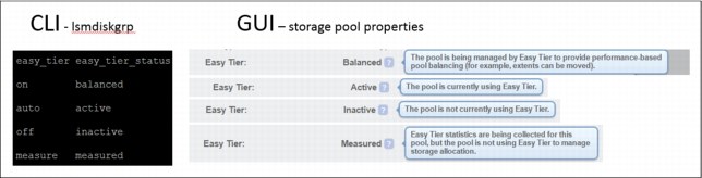
Figure 4-11 Easy Tier status for CLI and GUI
Easy Tier evaluation mode
Easy Tier evaluation mode is enabled for a storage pool with a single tier of storage when the status is changed with the command line to Measured. In this state, Easy Tier collects usage statistics for all the volumes in the pool. These statistics are collected over a 24-hour operational cycle, so you will have to wait several days to have multiple files to analyze. The statistics are copied from the control enclosures and viewed with the IBM Storage Tier Advisor Tool. Instructions for downloading and using the tool are available in the “Extracting and viewing performance data with the IBM Storage Tier Advisor Tool” topic at IBM Knowledge Center:
This tool is intended to supplement and support, but not replace, detailed preinstallation sizing and planning analysis.
Easy Tier considerations
When a volume is created in a pool that has Easy Tier active, the volume extents are initially be allocated only from the Enterprise tier. If that tier is not present or all the extents have been used, the volume will be assigned extents from other tiers.
To ensure optimal performance, all MDisks in a storage pool tier must have the same technology and performance characteristics.
Easy Tier functions best for workloads that have hot spots or data. Synthetic random workloads across an entire tier are not a good fit for this function. Also, you should not allocate all the space in the storage pool to volumes. You should leave some capacity free on the fastest tier for Easy Tier to use for migration.
4.3.7 Volume configuration
An individual volume is a member of one storage pool and one I/O Group:
•The storage pool defines which MDisks provided by the disk subsystem make up the volume.
•The I/O Group (two nodes make an I/O Group) defines which IBM FlashSystem V9000 nodes provide I/O access to the volume.
|
Important: No fixed relationship exists between I/O Groups and storage pools.
|
Perform volume allocation based on the following considerations:
•Optimize performance between the hosts and the IBM FlashSystem V9000 by attempting to distribute volumes evenly across available I/O Groups and nodes in the clustered system.
•Reach the level of performance, reliability, and capacity that you require by using the storage pool that corresponds to your needs (you can access any storage pool from any node). Choose the storage pool that fulfills the demands for your volumes regarding performance, reliability, and capacity.
•I/O Group considerations:
– With the IBM FlashSystem V9000, each building block that is connected into the cluster is an additional I/O Group for that clustered V9000 system.
– When you create a volume, it is associated with one node of an I/O Group. By default, every time that you create a new volume, it is associated with the next node using a round-robin algorithm. You can specify a preferred access node, which is the node through which you send I/O to the volume rather than using the round-robin algorithm. A volume is defined for an I/O Group.
– Even if you have eight paths for each volume, all I/O traffic flows toward only one node (the preferred node). Therefore, only four paths are used by the IBM Subsystem Device Driver (SDD). The other four paths are used only in the case of a failure of the preferred node or when concurrent code upgrade is running.
•Thin-provisioned volume considerations:
– When creating the thin-provisioned volume, be sure to understand the utilization patterns by the applications or group users accessing this volume. You must consider items such as the actual size of the data, the rate of creation of new data, and modifying or deleting existing data.
– Two operating modes for thin-provisioned volumes are available:
• Autoexpand volumes allocate storage from a storage pool on demand with minimal required user intervention. However, a misbehaving application can cause a volume to expand until it has consumed all of the storage in a storage pool.
• Non-autoexpand volumes have a fixed amount of assigned storage. In this case, the user must monitor the volume and assign additional capacity when required. A misbehaving application can only cause the volume that it uses to fill up.
– Depending on the initial size for the real capacity, the grain size and a warning level can be set. If a volume goes offline, either through a lack of available physical storage for autoexpand, or because a volume that is marked as non-expand had not been expanded in time, a danger exists of data being left in the cache until storage is made available. This situation is not a data integrity or data loss issue, but you must not rely on the IBM FlashSystem V9000 cache as a backup storage mechanism.
|
Important:
•Keep a warning level on the used capacity so that it provides adequate time to respond and provision more physical capacity.
•Warnings must not be ignored by an administrator.
•Use the autoexpand feature of the thin-provisioned volumes.
|
– When you create a thin-provisioned volume, you can choose the grain size for allocating space in 32 kilobytes (KB), 64 KB, 128 KB, or 256 KB chunks. The grain size that you select affects the maximum virtual capacity for the thin-provisioned volume. The default grain size is 256 KB, and is the preferred option. If you select 32 KB for the grain size, the volume size cannot exceed 260,000 GB. The grain size cannot be changed after the thin-provisioned volume is created.
Generally, smaller grain sizes save space but require more metadata access, which could adversely affect performance. If you will not be using the thin-provisioned volume as a FlashCopy source or target volume, use 256 KB to maximize performance. If you will be using the thin-provisioned volume as a FlashCopy
source or target volume, specify the same grain size for the volume and for the FlashCopy function.
source or target volume, specify the same grain size for the volume and for the FlashCopy function.
– Thin-provisioned volumes require more I/Os because of directory accesses. For truly random workloads with 70% read and 30% write, a thin-provisioned volume requires approximately one directory I/O for every user I/O.
– The directory is two-way write-back-cached (just like the IBM FlashSystem V9000 fast write cache), so certain applications perform better.
– Thin-provisioned volumes require more processor processing, so the performance per I/O Group can also be reduced.
– A thin-provisioned volume feature called zero detect provides clients with the ability to reclaim unused allocated disk space (zeros) when converting a fully allocated volume to a thin-provisioned volume using volume mirroring.
•Volume mirroring guidelines:
– With the IBM FlashSystem V9000 system in a high performance environment, this capability is only possible with a scale up or scale out solution as the single expansion of the first building block only provides one MDisk in one storage pool. If you are considering volume mirroring for data redundancy, a second expansion with its own storage pool would be needed for the mirror to be on.
– Create or identify two separate storage pools to allocate space for your mirrored volume.
– If performance is of concern, use a storage pool with MDisks that share the same characteristics. Otherwise, the mirrored pair can be on external virtualized storage with lesser-performing MDisks.
4.3.8 Host mapping (LUN masking)
Host mapping is the process of controlling which hosts have access to specific volumes within the system. Host mappings are only available if the system has open access disabled. Open access allows any host to access any volume on the system.
Host mapping is similar in concept to logical unit number (LUN) mapping or masking. LUN mapping is the process of controlling which hosts have access to specific logical units (LUs) within the disk controllers. LUN mapping is typically done at the storage system level. Host mapping is done at the software level.
For the host and application servers, the following guidelines apply:
•Each IBM FlashSystem V9000 control enclosure presents a volume to the SAN through host ports. Because two control enclosures are used in normal operations to provide redundant paths to the same storage, a host with two HBAs can see multiple paths to each LUN that is presented by the IBM FlashSystem V9000. Use zoning to limit the pathing from a minimum of two paths to the maximum that is available of eight paths, depending on the kind of high availability and performance that you want to have in your configuration.
The best approach is to use zoning to limit the pathing to four paths. The hosts must run a multipathing device driver to limit the pathing back to a single device. Native Multipath I/O (MPIO) drivers on selected hosts are supported. Details about which multipath driver to use for a specific host environment are in the IBM System Storage Interoperation Center:
|
Multipathing: These are examples of how to create multiple paths for highest redundancy:
•With two HBA ports, each HBA port zoned to the IBM FlashSystem V9000 ports 1:2 for a total of four paths.
•With four HBA ports, each HBA port zoned to the IBM FlashSystem V9000 ports 1:1 for a total of four paths.
Optional (n+2 redundancy): With four HBA ports, zone the HBA ports to the IBM FlashSystem V9000 ports 1:2 for a total of eight paths. This chapter uses the term HBA port to describe the SCSI initiator. The term V9000 port is used to describe the SCSI target. The maximum number of host paths per volume must not exceed eight.
|
•If a host has multiple HBA ports, each port must be zoned to a separate set of IBM FlashSystem V9000 ports to maximize high availability and performance.
•To configure greater than 256 hosts, you must configure the host to I/O Group mappings on the IBM FlashSystem V9000. Each I/O Group can contain a maximum of 256 hosts, so creating 512 host objects on a four-node IBM FlashSystem V9000 clustered system is possible. Volumes can be mapped only to a host that is associated with the I/O Group to which the volume belongs.
•You can use a port mask to control the node target ports that a host can access, which satisfies two requirements:
– As part of a security policy to limit the set of WWPNs that are able to obtain access to any volumes through a given IBM FlashSystem V9000 port.
– As part of a scheme to limit the number of logins with mapped volumes visible to a host multipathing driver, such as SDD, and therefore limit the number of host objects configured without resorting to switch zoning.
•The port mask is an optional parameter of the mkhost and chhost commands. The port mask is four binary bits. Valid mask values range from 0000 (no ports enabled) to 1111 (all ports enabled). For example, a mask of 0011 enables port 1 and port 2. The default value is 1111 (all ports enabled).
•The IBM FlashSystem V9000 supports connection to the Cisco MDS family and Brocade family. See the SSIC web page for the current support information:
4.3.9 SAN boot support
The IBM FlashSystem V9000 supports SAN boot or startup for IBM AIX, Microsoft Windows Server, and other operating systems. SAN boot support can change, so check the following SSIC web page regularly:
4.4 License features
IBM FlashSystem V9000 is available with many advanced optional features to enable many of the needs for today’s IT solutions. The following options can currently be licensed for the IBM FlashSystem V9000 solution:
•5641-VC7 FC 0663 External Virtualization
The system does not require a license for its own control and expansion enclosures; however, a capacity-based license is required for any external systems that are being virtualized. The system does not require an external virtualization license for external enclosures that are being used only to provide managed disks for a quorum disk and are not providing any capacity for volumes.
•5641-VC7 FC 9671 IBM Spectrum Virtualize FlashCopy for external storage
The FlashCopy function copies the contents of a source volume to a target volume. This license is capacity-based.
•5641-VC7 FC 9679 IBM Spectrum Virtualize Remote Mirroring Software for external storage
The remote-copy function allows the use of Metro Mirror and Global Mirror functions. This function enables you to set up a relationship between volumes on two systems, so that updates that are made by an application to one volume are mirrored on the other volume. The volumes can be in the same system or on two different systems. This license is capacity-based.
•5639-FC7 FC 0708 IBM Spectrum Virtualize Real-time Compression for external storage
With the compression function data is compressed as it is written to the drive, saving additional capacity for the system. This license is capacity-based.
A strong suggestion is to add FC AH1A - Compression Accelerator Adapter. With the AE2 expansion, there is also a licensed feature for encryption:
– Feature code AF14 - Encryption Enablement Pack.
|
Note: When you use the External Virtualization Feature, all IBM FlashSystem V9000 features, except for the encryption option, are able to be extended to include the external capacity.
|
4.4.1 Encryption feature
The IBM FlashSystem V9000 Encryption feature is offered with the IBM FlashSystem V9000 under the following feature:
•Feature code AF14 - Encryption Enablement Pack:
– Includes three USB keys on which to store the encryption key.
– Maximum feature quantity is eight (for a full scale up and scale out solution).
– Enables data encryption at rest on the internal flash memory MDisks.
This feature requires the use of three USB keys to store the encryption key when the feature is enabled and installed. If necessary, there is a rekey feature that can also be performed.
When the encryption feature is being installed and IBM FlashSystem V9000 cluster GUI is used, the USB keys must be installed in the USB ports that are available on the AC2 enclosure. Figure 4-12 shows the location of USB ports on the AC2 control enclosure. Any AC2 control enclosure can be used for inserting the USB keys.
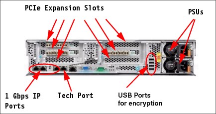
Figure 4-12 AC2 rear view
When the encryption feature is being installed and IBM FlashSystem V9000 cluster GUI is used, the USB keys must be installed in the USB ports that are available on the AC3 enclosure. Figure 4-13 (rear view) shows the location of USB ports on the AC3 control enclosures. Any AC3 control enclosure can be used for inserting the USB keys.
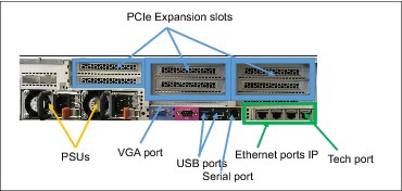
Figure 4-13 AC3 control enclosure rear view
IBM Security Key Lifecycle Manager (V7.8 and later)
IBM FlashSystem V9000 Software V7.8 adds improved security with support for encryption key management software that complies with the Key Management Interoperability Protocol (KMIP) standards, such as IBM Security Key Lifecycle Manager (SKLM) to help centralize, simplify, and automate the encryption key management process.
Prior to IBM FlashSystem V9000 Software V7.8, you can enable encryption by using USB flash drives to copy the encryption key to the system.
|
Note: If you are creating a new cluster with V 7.8, you have the option to either use USB encryption or key server encryption but not both. The USB flash drive method and key server method cannot be used in parallel on the same system. Existing clients that are currently using USB encryption will have to wait for a future release before being able to move to key server encryption. The migration of a local (USB) key to a centrally managed key (SKLM key server) is not yet available at the time of this writing.
|
For more information about encryption technologies supported by other IBM storage devices, see the IBM DS8880 Data-at-rest Encryption, REDP-4500.
4.4.2 External virtualized storage configuration
The IBM FlashSystem V9000 system provides symmetric virtualization.
When using the external virtualization feature, all the IBM FlashSystem V9000 features except the encryption option are able to be extended to include the external capacity.
External virtualized storage is a licensed feature for the IBM FlashSystem V9000 and requires configuration planning to be applied for all storage systems that are to be attached to the IBM FlashSystem V9000.
See the IBM System Storage Interoperation Center (SSIC) for a list of currently supported storage subsystems:
Apply the following general guidelines for external storage subsystem configuration planning:
•In the SAN, storage controllers that are used by the IBM FlashSystem V9000 clustered system must be connected through SAN switches. Direct connection between the IBM FlashSystem V9000 and external storage controllers is not supported.
•Multiple connections are allowed from the redundant controllers in the disk subsystem to improve data bandwidth performance. Having a connection from each redundant controller in the disk subsystem to each counterpart SAN is not mandatory but it is a preferred practice.
•All AC2 or AC3 control enclosures in an IBM FlashSystem V9000 clustered system must be able to see the same set of ports from each storage subsystem controller. Violating this guideline causes the paths to become degraded. This degradation can occur as a result of applying inappropriate zoning and LUN masking.
If you do not have an external storage subsystem that supports a round-robin algorithm, make the number of MDisks per storage pool a multiple of the number of storage ports that are available. This approach ensures sufficient bandwidth to the storage controller and an even balance across storage controller ports. In general, configure disk subsystems as though no IBM FlashSystem V9000 is involved.
The following guidelines are suggested:
•Disk drives:
– Exercise caution with large disk drives so that you do not have too few spindles to handle the load.
– RAID 5 is suggested for most workloads.
•Array sizes:
– An array size of 8+P or 4+P is suggested for the IBM DS4000® and DS5000™ families, if possible.
– Use the DS4000 segment size of 128 KB or larger to help the sequential performance.
– Upgrade to EXP810 drawers, if possible.
– Create LUN sizes that are equal to the RAID array and rank size. If the array size is greater than 2 TB and the disk subsystem does not support MDisks larger than 2 TB, create the minimum number of LUNs of equal size.
– An array size of 7+P is suggested for the V3700, V5000, and V7000 Storwize families.
– When adding more disks to a subsystem, consider adding the new MDisks to existing storage pools versus creating additional small storage pools.
•Maximum of 1024 worldwide node names (WWNNs) per cluster:
– EMC DMX/SYMM, all HDS, and Oracle/HP HDS clones use one WWNN per port. Each WWNN appears as a separate controller to the IBM FlashSystem V9000.
– IBM, EMC CLARiiON, and HP use one WWNN per subsystem. Each WWNN appears as a single controller with multiple ports/WWPNs, for a maximum of 16 ports/WWPNs per WWNN.
•IBM DS8000® using four of, or eight of, the 4-port HA cards:
– Use ports 1 and 3 or ports 2 and 4 on each card (it does not matter for 8 Gb cards).
– This setup provides 8 or 16 ports for IBM FlashSystem V9000 use.
– Use 8 ports minimum, for up to 40 ranks.
– Use 16 ports for 40 or more ranks; 16 is the maximum number of ports.
– Both systems have the preferred controller architecture, and IBM FlashSystem V9000 supports this configuration.
– Use a minimum of 4 ports, and preferably 8 or more ports, up to a maximum of 16 ports, so that more ports equate to more concurrent I/O that is driven by the IBM FlashSystem V9000.
– Support is available for mapping controller A ports to fabric A and controller B ports to fabric B or cross-connecting ports to both fabrics from both controllers. The cross-connecting approach is preferred to avoid auto-volume transfer (AVT) and resulting trespass issues from occurring if a fabric or all paths to a fabric fail.
•IBM System Storage DS3500, DCS3700, and DCS3860, and EMC CLARiiON CX series:
– All of these systems have the preferred controller architecture, and IBM FlashSystem V9000 supports this configuration.
– Use a minimum of four ports, and preferably eight or more ports, up to a maximum of 16 ports, so that more ports equate to more concurrent I/O that is driven by the IBM FlashSystem V9000.
– Support is available for mapping controller A ports to Fabric A and controller B ports to Fabric B or cross-connecting ports to both fabrics from both controllers. The cross-connecting approach is preferred to avoid AVT/Trespass occurring if a fabric or all paths to a fabric fail.
•Storwize family:
– Use a minimum of four ports, and preferably eight ports.
•IBM XIV requirements:
– The use of XIV extended functions, including snaps, thin provisioning, synchronous replication (native copy services), and LUN expansion of LUNs presented to the IBM FlashSystem V9000 is not supported.
– A maximum of 511 LUNs from one XIV system can be mapped to an IBM FlashSystem V9000 clustered system.
•Full 15-module XIV recommendations (161 TB usable):
– Use two interface host ports from each of the six interface modules.
– Use ports 1 and 3 from each interface module and zone these 12 ports with all forward facing IBM FlashSystem V9000 node ports.
– Create 48 LUNs of equal size, each of which is a multiple of 17 GB. This creates approximately 1632 GB if you are using the entire full frame XIV with the IBM FlashSystem V9000.
– Map LUNs to the IBM FlashSystem V9000 as 48 MDisks, and add all of them to the single XIV storage pool so that the IBM FlashSystem V9000 drives the I/O to four MDisks and LUNs for each of the 12 XIV FC ports. This design provides a good queue depth on the IBM FlashSystem V9000 to drive XIV adequately.
•Six-module XIV recommendations (55 TB usable):
– Use two interface host ports from each of the two active interface modules.
– Use ports 1 and 3 from interface modules 4 and 5. (Interface module 6 is inactive). Also, zone these four ports with all forward facing IBM FlashSystem V9000 node ports.
– Create 16 LUNs of equal size, each of which is a multiple of 17 GB. This creates approximately 1632 GB if you are using the entire XIV with the IBM FlashSystem V9000.
– Map the LUNs to the IBM FlashSystem V9000 as 16 MDisks, and add all of them to the single XIV storage pool, so that the IBM FlashSystem V9000 drives I/O to four MDisks and LUNs per each of the four XIV FC ports. This design provides a good queue depth on the IBM FlashSystem V9000 to drive the XIV adequately.
•Nine-module XIV recommendations (87 TB usable):
– Use two interface host ports from each of the four active interface modules.
– Use ports 1 and 3 from interface modules 4, 5, 7, and 8 (interface modules 6 and 9 are inactive). Zone the port with all of the forward-facing IBM FlashSystem V9000 node ports.
– Create 26 LUNs of equal size, each of which is a multiple of 17 GB. This creates approximately 1632 GB approximately if you are using the entire XIV with the IBM FlashSystem V9000.
– Map the LUNs to the IBM FlashSystem V9000 as 26 MDisks, and map them all to the single XIV storage pool so that the IBM FlashSystem V9000 drives I/O to three MDisks and LUNs on each of the six ports and four MDisks and LUNs on the other two XIV FC ports. This design provides a useful queue depth on IBM FlashSystem V9000 to drive XIV adequately.
•Configure XIV host connectivity for the IBM FlashSystem V9000 clustered system:
– Create one host definition on XIV, and include all forward-facing IBM FlashSystem V9000 node WWPNs.
– You can create clustered system host definitions (one per I/O Group), but the preceding method is easier.
– Map all LUNs to all forward-facing IBM FlashSystem V9000 node WWPNs.
4.4.3 Advanced copy services
IBM FlashSystem V9000 offers these advanced copy services:
•FlashCopy
•Metro Mirror
•Global Mirror
FlashCopy guidelines
The FlashCopy function copies the contents of a source volume to a target volume. The FlashCopy function is also used to create cloud snapshots of volumes in systems that have transparent cloud tiering enabled. The used capacity for FlashCopy mappings is the sum of all of the volumes that are the source volumes of a FlashCopy mapping and volumes with cloud snapshots. This license is capacity-based.
Consider these FlashCopy guidelines:
•Identify each application that must have a FlashCopy function implemented for its volume.
•FlashCopy is a relationship between volumes. Those volumes can belong to separate storage pools and separate storage subsystems.
•You can use FlashCopy for backup purposes by interacting with the IBM Spectrum Protect Agent or for cloning a particular environment.
•Define which FlashCopy best fits your requirements: no copy, full copy, thin-provisioned, or incremental.
•Define which FlashCopy rate best fits your requirement in terms of the performance and the time to complete the FlashCopy. Table 4-10 on page 170 shows the relationship of the background copy rate value to the attempted number of grains to be split per second.
•Define the grain size that you want to use. A grain is the unit of data that is represented by a single bit in the FlashCopy bitmap table. Larger grain sizes can cause a longer FlashCopy elapsed time and a higher space usage in the FlashCopy target volume. Smaller grain sizes can have the opposite effect. Remember that the data structure and the source data location can modify those effects.
In an actual environment, check the results of your FlashCopy procedure in terms of the data that is copied at every run and in terms of elapsed time, comparing them to the new IBM FlashSystem V9000 FlashCopy results. Eventually, adapt the grain/second and the copy rate parameter to fit your environment’s requirements.
Table 4-10 shows the relationship of the copy rate value to grains split per second.
Table 4-10 Grain splits per second
|
User percentage
|
Data copied per second
|
256 KB grain per second
|
64 KB grain per second
|
|
1 - 10
|
128 KB
|
0.5
|
2
|
|
11 - 20
|
256 KB
|
1
|
4
|
|
21 - 30
|
512 KB
|
2
|
8
|
|
31 - 40
|
1 MB
|
4
|
16
|
|
41 - 50
|
2 MB
|
8
|
32
|
|
51 - 60
|
4 MB
|
16
|
64
|
|
61 - 70
|
8 MB
|
32
|
128
|
|
71 - 80
|
16 MB
|
64
|
256
|
|
81 - 90
|
32 MB
|
128
|
512
|
|
91 - 100
|
64 MB
|
256
|
1024
|
Metro Mirror and Global Mirror guidelines
The remote-copy function allows the use of Metro Mirror and Global Mirror functions. This function enables you to set up a relationship between volumes on two systems, so that updates that are made by an application to one volume are mirrored on the other volume. The volumes can be in the same system or on two different systems. This license is capacity-based.
IBM FlashSystem V9000 supports both intracluster and intercluster Metro Mirror and Global Mirror. From the intracluster point of view, any single clustered system is a reasonable candidate for a Metro Mirror or Global Mirror operation. Intercluster operation, however, needs at least two clustered systems that are separated by several moderately high-bandwidth links.
Figure 4-14 shows a schematic of Metro Mirror connections and zones.
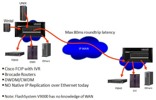
Figure 4-14 Replication connections and zones
Figure 4-14 contains two redundant fabrics. Only Fibre Channel switched links can be used to connect to the long-distance wide area networks (WANs) technologies to be used for extending the distance between the two IBM FlashSystem V9000 clustered systems. Two broadband categories are currently available:
•FC extenders
•SAN multiprotocol routers
Because of the more complex interactions involved, IBM explicitly tests products of this class for interoperability with the IBM FlashSystem V9000. You can obtain the current list of supported SAN routers on the IBM SSIC web page:
IBM has tested several FC extenders and SAN router technologies with the IBM FlashSystem V9000. You must plan, install, and test FC extenders and SAN router technologies with the IBM FlashSystem V9000 so that the following requirements are met:
•The round-trip latency between sites must not exceed 80 ms (40 ms one way). For Global Mirror, this limit supports a distance between the primary and secondary sites of up to 8000 km (4970.96 miles) using a planning assumption of 100 km (62.13 miles) per 1 ms of round-trip link latency.
•The latency of long-distance links depends on the technology that is used to implement them. A point-to-point dark fibre-based link typically provides a round-trip latency of 1 ms per 100 km (62.13 miles) or better. Other technologies provide longer round-trip latencies, which affect the maximum supported distance.
•The configuration must be tested with the expected peak workloads.
•When Metro Mirror or Global Mirror is used, a certain amount of bandwidth is required for IBM FlashSystem V9000 intercluster heartbeat traffic. The amount of traffic depends on how many nodes are in each of the two clustered systems.
Table 4-11 shows the amount of heartbeat traffic, in megabits per second (Mbps), that is generated by various sizes of clustered systems that can be involved in a mirroring partnership.
Table 4-11 Inter-cluster heartbeat traffic (megabits per second)
|
Cluster 1
|
Cluster 2 (in Mbps)
|
|||
|
|
2 control enclosures
|
4 control enclosures
|
6 control enclosures
|
8 control enclosures
|
|
2 control enclosures
|
2.6
|
4.0
|
5.4
|
6.7
|
|
4 control enclosures
|
4.0
|
5.5
|
7.1
|
8.6
|
|
6 control enclosures
|
5.4
|
7.1
|
8.8
|
10.5
|
|
8 control enclosures
|
6.7
|
8.6
|
10.5
|
12.4
|
•These numbers represent the total traffic between the two clustered systems when no I/O is taking place to mirrored volumes. Half of the data is sent by one clustered system and half of the data is sent by the other clustered system. The traffic is divided evenly over all available intercluster links. Therefore, if you have two redundant links, half of this traffic is sent over each link during fault-free operation.
•The bandwidth between sites must, at the least, be sized to meet the peak workload requirements, in addition to maintaining the maximum latency that has been specified previously. You must evaluate the peak workload requirement by considering the average write workload over a period of one minute or less, plus the required synchronization copy bandwidth.
With no active synchronization copies and no write I/O disks in Metro Mirror or Global Mirror relationships, the IBM FlashSystem V9000 protocols operate with the bandwidth that is indicated in Figure 4-14 on page 171. However, you can only determine the true bandwidth that is required for the link by considering the peak write bandwidth to volumes participating in Metro Mirror or Global Mirror relationships and adding it to the peak synchronization copy bandwidth.
•If the link between the sites is configured with redundancy so that it can tolerate single failures, you must size the link so that the bandwidth and latency statements continue to be true even during single failure conditions.
•The configuration is tested to simulate failure of the primary site (to test the recovery capabilities and procedures), including eventual fail back to the primary site from the secondary.
•The configuration must be tested to confirm that any failover mechanisms in the intercluster links interoperate satisfactorily with the IBM FlashSystem V9000.
•The FC extender must be treated as a normal link.
•The bandwidth and latency measurements must be made by, or on behalf of, the client. They are not part of the standard installation of the IBM FlashSystem V9000 by IBM. Make these measurements during installation, and record the measurements. Testing must be repeated after any significant changes to the equipment that provides the intercluster link.
Global Mirror guidelines
Consider these guidelines:
•When using IBM FlashSystem V9000 Global Mirror, all components in the SAN must be capable of sustaining the workload that is generated by application hosts and the Global Mirror background copy workload. Otherwise, Global Mirror can automatically stop your relationships to protect your application hosts from increased response times. Therefore, it is important to configure each component correctly.
•Use a SAN performance monitoring tool, such as IBM Spectrum Control (formerly IBM Tivoli Storage Productivity Center), which enables you to continuously monitor the SAN components for error conditions and performance problems. This tool helps you detect potential issues before they affect your disaster recovery solution.
•The long-distance link between the two clustered systems must be provisioned to allow for the peak application write workload to the Global Mirror source volumes, plus the client-defined level of background copy.
•The peak application write workload ideally must be determined by analyzing the IBM FlashSystem V9000 performance statistics.
•Statistics must be gathered over a typical application I/O workload cycle, which might be days, weeks, or months, depending on the environment in which the IBM FlashSystem V9000 is used. These statistics must be used to find the peak write workload that the link must be able to support.
•Characteristics of the link can change with use; for example, latency can increase as the link is used to carry an increased bandwidth. The user must be aware of the link’s behavior in such situations and ensure that the link remains within the specified limits. If the characteristics are not known, testing must be performed to gain confidence of the link’s suitability.
•Users of Global Mirror must consider how to optimize the performance of the long-distance link, which depends on the technology that is used to implement the link. For example, when transmitting FC traffic over an IP link, an approach you might want to take is to enable jumbo frames to improve efficiency.
•Using Global Mirror and Metro Mirror between the same two clustered systems is supported.
•Using Global Mirror and Metro Mirror between the IBM FlashSystem V9000 clustered system and IBM Storwize systems with a minimum code level of 7.3 is supported.
|
Note: Metro to Global Mirror to IBM FlashSystem V9000 target system is not supported, because the risk of overwhelming receive buffers is too great.
|
•Support exists for cache-disabled volumes to participate in a Global Mirror relationship; however, doing so is not a preferred practice.
•The gmlinktolerance parameter of the remote copy partnership must be set to an appropriate value. The default value is 300 seconds (5 minutes), which is appropriate for most clients.
•During SAN maintenance, you must choose to reduce the application I/O workload during the maintenance (so that the degraded SAN components are capable of the new workload); disable the gmlinktolerance feature; increase the gmlinktolerance value (meaning that application hosts might see extended response times from Global Mirror volumes); or stop the Global Mirror relationships.
If the gmlinktolerance value is increased for maintenance lasting x minutes, it must only be reset to the normal value x minutes after the end of the maintenance activity.
If gmlinktolerance is disabled during maintenance, it must be re-enabled after the maintenance is complete.
Global Mirror volumes must have their preferred nodes evenly distributed between the nodes of the clustered systems. Each volume within an I/O Group has a preferred node property that can be used to balance the I/O load between nodes in that group.
Figure 4-15 shows the correct relationship between volumes in a Metro Mirror or Global Mirror solution.
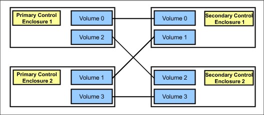
Figure 4-15 Correct volume relationship
•The capabilities of the storage controllers at the secondary clustered system must be provisioned to allow for the peak application workload to the Global Mirror volumes, plus the client-defined level of background copy, plus any other I/O being performed at the secondary site. The performance of applications at the primary clustered system can be limited by the performance of the back-end storage controllers at the secondary clustered system to maximize the amount of I/O that applications can perform to Global Mirror volumes.
•Be sure to perform a complete review before using Serial Advanced Technology Attachment (SATA) for Metro Mirror or Global Mirror secondary volumes. Using a slower disk subsystem for the secondary volumes for high-performance primary volumes can mean that the IBM FlashSystem V9000 cache might not be able to buffer all the writes, and flushing cache writes to SATA might slow I/O at the production site.
•Storage controllers must be configured to support the Global Mirror workload that is required of them. You can dedicate storage controllers to only Global Mirror volumes, configure the controller to ensure sufficient quality of service (QoS) for the disks that are being used by Global Mirror, or ensure that physical disks are not shared between Global Mirror volumes and other I/O (for example, by not splitting an individual RAID array).
•MDisks within a Global Mirror storage pool must be similar in their characteristics, for example, RAID level, physical disk count, and disk speed. This requirement is true of all storage pools, but it is particularly important to maintain performance when using Global Mirror.
•When a consistent relationship is stopped, for example, by a persistent I/O error on the intercluster link, the relationship enters the consistent_stopped state. I/O at the primary site continues, but the updates are not mirrored to the secondary site. Restarting the relationship begins the process of synchronizing new data to the secondary disk. While this synchronization is in progress, the relationship is in the inconsistent_copying state.
Therefore, the Global Mirror secondary volume is not in a usable state until the copy has completed and the relationship has returned to a Consistent state. For this reason, the suggestion is to create a FlashCopy of the secondary volume before restarting the relationship.
When started, the FlashCopy provides a consistent copy of the data, even while the Global Mirror relationship is copying. If the Global Mirror relationship does not reach the Synchronized state (if, for example, the intercluster link experiences further persistent I/O errors), the FlashCopy target can be used at the secondary site for disaster recovery purposes.
•If you plan to use a Fibre Channel over IP (FCIP) intercluster link, an important step is to design and size the pipe correctly.
Example 4-2 shows a best-guess bandwidth sizing formula.
Example 4-2 WAN link calculation example
Amount of write data within 24 hours times 4 to allow for peaks
Translate into MB/s to determine WAN link needed
Example:
250 GB a day
250 GB * 4 = 1 TB
24 hours * 3600 secs/hr. = 86400 secs
1,000,000,000,000/ 86400 = approximately 12 MB/s,
Which means OC3 or higher is needed (155 Mbps or higher)
•If compression is available on routers or WAN communication devices, smaller pipelines might be adequate.
|
Note: Workload is probably not evenly spread across 24 hours. If extended periods of high-data change rates occur, consider suspending Global Mirror during that time frame.
|
•If the network bandwidth is too small to handle the traffic, the application write I/O response times might be elongated. For the IBM FlashSystem V9000, Global Mirror must support short-term “Peak Write” bandwidth requirements.
•You must also consider the initial sync and resync workload. The Global Mirror partnership’s background copy rate must be set to a value that is appropriate to the link and secondary back-end storage. The more bandwidth that you give to the sync and resync operation, the less workload can be delivered by the IBM FlashSystem V9000 for the regular data traffic.
•Do not propose Global Mirror if the data change rate will exceed the communication bandwidth, or if the round-trip latency exceeds 80 - 120 ms. A round-trip latency that is greater than 80 microseconds, requires submission of either Solution for Compliance in a Regulated Environment (SCORE) or request for price quotation (RPQ).
4.4.4 Real-time Compression
The IBM FlashSystem V9000 Real-time Compression feature uses additional hardware that is dedicated to the improvement of the Real-time Compression functionality. When ordered, the feature includes two Compression Acceleration Cards per control enclosure for the I/O Group to support compressed volumes.
The compression accelerator feature is ordered, by default, with Real-time Compression software:
•Feature code AH1A - Compression Acceleration Card:
– Includes one Compression Acceleration Card.
– Maximum feature quantity is two.
When you size the number of Compression Acceleration cards per node, be attentive to several considerations. If your active data workload is greater than 8 TB per I/O Group, consider deploying both Compression Acceleration cards per node. With a single Compression Acceleration Card in each node, the existing recommendation on the number of compressed volumes able to be managed per I/O group remains the same at 200 volumes. However, with the addition of the second Compression Acceleration card in each node (a total of four cards per I/O group), the total number of managed compressed volumes increases to 512.
|
Note: Active Data Workload is typically 5 - 8% of the total managed capacity. In a single I/O Group, 8 TB of active data equates to approximately 160 TB managed. In a 4 by 4 IBM FlashSystem V9000 configuration, this equates to 32 TB of active data (8 TB per I/O Group).
|
4.5 Data migration
Data migration is an extremely important part of an IBM FlashSystem V9000 implementation. Therefore, you must accurately prepare a data migration plan. You might need to migrate your data for one of these reasons:
•To redistribute workload within a clustered system across the disk subsystem
•To move workload onto newly installed storage
•To move workload off old or failing storage, ahead of decommissioning it
•To move workload to rebalance a changed workload
•To migrate data from an older disk subsystem to FlashSystem V9000 managed storage
•To migrate data from one disk subsystem to another disk subsystem
Because multiple data migration methods are available, choose the method that best fits your environment, your operating system platform, your kind of data, and your application’s service level agreement (SLA).
Data migration has the following characteristics and applications:
•Changes the MDisks to which the volume is allocated
•Does not disrupt access to the volume data
•Can be used when removing MDisks from a clustered system
•Can move data to an MDisk that has appropriate performance for host requirements
•Can move data from image mode volumes to MDisks when adding a system to an existing SAN infrastructure.
•Can migrate striped and sequential volumes to an image mode volume
Data migration can be based on these items:
•Operating system Logical Volume Manager (LVM) or commands
•Special data migration software
•The IBM FlashSystem V9000 data migration feature
With data migration, apply the following guidelines:
•Choose which data migration method best fits your operating system platform, your kind of data, and your SLA.
•Check IBM System Storage Interoperation Center (SSIC) for the storage system to which your data is being migrated:
•Choose where you want to place your data after migration in terms of the storage pools that relate to a specific storage subsystem tier.
•Check whether enough free space or extents are available in the target storage pool.
•Decide if your data is critical and must be protected by a volume mirroring option or if it must be replicated in a remote site for disaster recovery.
•To minimize downtime during the migration, prepare offline all of the zone and LUN masking and host mappings that you might need.
•Prepare a detailed operation plan so that you do not overlook anything at data migration time.
•Run a data backup before you start any data migration. Data backup must be part of the regular data management process.
4.6 IBM FlashSystem V9000 configuration backup procedure
Configuration backup is the process of extracting configuration settings from a clustered system and writing it to disk. The configuration restore process uses backup configuration data files for the system to restore a specific system configuration. Restoring the system configuration is an important part of a complete backup and disaster recovery solution.
Only the data that describes the system configuration is backed up. You must back up your application data by using the appropriate backup methods.
To enable routine maintenance, the configuration settings for each system are stored on each node. If power fails on a system or if a node in a system is replaced, the system configuration settings are automatically restored when the repaired node is added to the system. To restore the system configuration in a disaster (if all nodes in a system are lost simultaneously), plan to back up the system configuration settings to tertiary storage. You can use the configuration backup functions to back up the system configuration. The preferred practice is to implement an automatic configuration backup by applying the configuration backup command.
The virtualization map is stored on the quorum disks of external MDisks, and is accessible to every IBM FlashSystem V9000 control enclosure.
For complete disaster recovery, regularly back up the business data that is stored on volumes at the application server level or the host level.
For detailed procedural steps see 13.3.7, “Backup IBM FlashSystem V9000 configuration” on page 636.
..................Content has been hidden....................
You can't read the all page of ebook, please click here login for view all page.