
6
IP-Based WPAN and WLAN
WPAN networks have adopted protocols that are typically not Transmission Control Protocol/Internet Protocol (TCP/IP), at least from the outset. The protocol stacks for Bluetooth, Zigbee, and Z-Wave have similarities to a true TCP/IP protocol but don't inherently communicate over TCP/IP. There are adaptations of IP on Zigbee (using Zigbee-IP) and IP over Bluetooth (using IPSP to support 6LoWPAN) that do exist. Later in this chapter, we will cover an example of a WPAN using the 802.15.4 protocol with a true IPv6 (Thread) compatible layer capable of joining any IPv6 network.
This chapter will also cover the standards around Wi-FiTM using the IEEE 802.11 protocols. While typically thought of as a wireless LAN (WLAN), 802.11 protocols are pervasive and of use in IoT deployments, especially in smart sensors and gateway hubs. This chapter will provide a formal treatment of the 802.11 Wi-Fi catalog of standards including the new IEEE802.11ac high-speed protocol. 802.11 also extends into the world of IoT for the vehicle-to-vehicle and transportation market using the 802.11p protocol, which will also be covered. Finally, this chapter will explore the IEEE 802.11ah specification, which is a wireless LAN solution built on the 802.11 protocol but targeted explicitly for power and cost-constrained IoT sensor devices.
The following topics will be covered in the chapter:
- TCP/IP
- WPAN with IP – 6LoWPAN
- WPAN with IP – Thread
- IEEE 802.11 protocols and WLAN
TCP/IP
Supporting an IP layer in a protocol stack does consume resources that could be applied elsewhere. However, there are key benefits in building an IoT system that allows devices to communicate over TCP/IP. We will begin by enumerating these benefits; however, it is the role of the architect to balance the cost of these services and features against the impact on a system.
From an ecosystem point of view, regardless of the protocol used at a sensor level, the sensor data will ultimately be fed into a public, private, or hybrid cloud for analysis, control, or monitoring. Outside of the WPAN, the world is TCP/IP-based, as we see in WLAN and WAN configurations.
IP is the standard form of global communication for various reasons:
- Ubiquity: IP stacks are provided by nearly every operating system and every medium. IP communication protocols are capable of running on various WPAN systems, cellular, copper wire, fiber-optic, PCI Express, and satellite systems. IP specifies the exact format for all data communications and the rules used to communicate, acknowledge, and manage connectivity.
- Longevity: TCP was established in 1974, and the IPv4 standard still in use today was designed in 1978. It has withstood the test of time for 40 years. Longevity is paramount for many industrial and field IoT solutions that must support devices and systems for decades. Various other proprietary protocols have been designed by various manufacturers in those 40 years, such as AppleTalk, SNA, DECnet, and Novell IPX, but none have gained the market traction that IP has.
- Standards-based: TCP/IP is governed by the Internet Engineering Task Force (IETF). The IETF maintains a set of open standards focused on the Internet protocol.
- Scalability: IP has demonstrated scale and adoption. IP networks have demonstrated massive scaling to billions of users and many more devices. IPv6 could provide a unique IP address to every atom comprising Earth and still support 100 more worlds.
- Reliability: IP at its heart is a reliable protocol for data transmission. It accomplishes this through a packet delivery system based on a connectionless network. IP is connectionless because each packet is treated independently from one another. The data delivery is also referred to as best-effort delivery because all attempts will be made to transmit a packet through various routes. The strength of this model allows an architect to replace the delivery mechanism with another—essentially replacing layers one and two of the stack with something else (for example, Wi-Fi with cellular).
- Manageability: Various tools exist to manage IP networks and devices on an IP network. Modeling tools, network sniffers, diagnostic tools, and various appliances exist to assist in building, scaling, and maintaining networks.
The transport layer is also worth considering. While IP addresses the need for a well-supported and robust network layer, TCP and Universal Datagram Protocol (UDP) are needed for the transport layer. The transport layer is responsible for end-to-end communication. The logical communication between different hosts and various network components is governed at this level. TCP is used for connection-oriented transmissions, whereas UDP is used for connectionless transmissions. UDP is naturally much simpler to implement than TCP, but not as resilient. Both services provide segment reordering as packets are not guaranteed to be delivered in order using an IP protocol. TCP also provides the layer of reliability to an unreliable IP network layer through the use of acknowledgment messages and retransmissions of lost messages. Additionally, TCP provides flow control using sliding windows and congestion avoidance algorithms. UDP provides a lightweight, high-speed method to broadcast data to various devices that may or may not be present or reliable.
The following is the standard seven-layer Open Source Interconnection (OSI) model stack:

Figure 1: Full seven-layer OSI model. TCP/IP represent layers 3 and 4.
The OSI stack provides a reference to how many protocols are built layer upon layer. The model starts at layer 1, which is usually a physical entity like a network port or physical interface (PHY). Each layer adds various headers and footers that surround a packet. This process continues up the stack as a larger and larger packet structure grows as headers and footers are appended.
From an IoT perspective, bringing IP close to the source of data bridges two worlds of data management. The information technology (IT) role manages the infrastructure, security, and provisioning of networks and things on the network. The operational technology (OT) role manages the health and throughput of the system that functions to produce something. These two roles have traditionally been separated, as things such as sensors, meters, and programmable controllers have not been connected, at least directly.
Proprietary standards have governed OT systems, at least from an industrial IoT perspective.
WPAN with IP – 6LoWPAN
In an effort to bring IP addressability to the smallest and most resource-constrained devices, the concept of 6LoWPAN was formed in 2005. A working group formalized the design in the IETF under the specification RFC 4944 (request for comment) and later updated with RFC 6282 to address header compression and RFC 6775 for neighbor discovery. The consortium is closed; however, the standard is open for anyone to use and implement.
6LoWPAN is an acronym that stands for IPV6 over Low-Power Wireless Personal Area Networks. The intent is for IP networking over low-power RF communication systems for devices that are power and space constrained and do not need high-bandwidth networking services. The protocol can be used with other WPAN communications such as 802.15.4, as well as Bluetooth, sub-1 GHz RF protocols, and power-line controller (PLC). The principal advantage of 6LoWPAN is that the simplest of sensors can have IP addressability and act as a network citizen over 3G/4G/LTE/Wi-Fi/Ethernet routers. A secondary effect is that IPV6 provides significant theoretical addressability of 2128 or 3.4x1038 unique addresses. This would sufficiently cover an estimated 50 billion Internet-connected devices and continue to cover those devices well beyond that. Therefore, 6LoWPAN is well-suited for IoT growth.
IEEE 802.11 protocols and WLAN
One of the first adopters of the ISM bands that the FCC freed for unlicensed use was the IEEE 802.11 technology. The IEEE 802.11 is a suite of protocols with a rich history and different use cases. 802.11 is the specification defining the Media Access Control (MAC) and physical layer (PHY) of a networking stack. The definition and specifications are governed by the IEEE LAN/MAN Standards Committee. Wi-Fi is the definition of WLAN based on the IEEE802.11 standards but maintained and governed by the nonprofit Wi-Fi Alliance.
802.11 owes its creation to NCR in 1991, which first developed the wireless protocol as a means of networking cash registers. It wasn't until 1999 when the Wi-Fi Alliance was formed that the technology became ubiquitous and pervasive in the burgeoning PC and notebook market. The original protocol is vastly different than modern 802.11 b/g/n/ac protocols. It only supported a 2 Mbps data rate with forward error correction.
The success of IEEE802.11 can be attributed to the layered stack approach of the OSI model. Simply replacing the MAC and PHY layers with IEEE802.11 layers allowed existing TCP/IP infrastructure to be used effortlessly.
Today, nearly every mobile device, notebook, tablet, embedded system, toy, and video game incorporates an IEEE802.11 radio of some kind. That said, 802.11 has had a storied past, particularly in the security model. The original 802.11 security model was based on the UC Berkeley Wired Equivalent Privacy security mechanism, which was later proven to be unreliable and easily compromised. Several notable exploits, including the TJ Maxx data breach through 802.11 WEP in 2007, resulted in 45 million stolen credit cards. Today, Wi-Fi Protected Access (WPA) and WPA2 using AES 256-bit pre-shared keys have certainly tightened up security, and WEP is rarely used.
This section will detail some of the differences in the 802.11 protocols and particular information relevant to the IoT architect. We will detail the current IEEE802.11ac design and then examine 802.11ah HaLow and 802.11p V2V, as all three are relevant to the IoT.
An outstanding comparison of 802.11 standards can be found in R. Shaw, S Sharma, Comparative Study of IEEE 802.11 a, b, g & n Standards, International Journal of Engineering Research and Technology (IJERT), V3 Issue 4, April 2014.
IEEE 802.11 suite of protocols and comparison
The IEEE LAN/MAN Standards Committee maintains and governs the IEEE 802 specification(s). The original 802.11 goal was to provide a link layer protocol for wireless networking. This evolved from the 802.11 base specification to 802.11ac in 2013. Since then, the working group has focused on other areas, as the following chart illustrates. Specific 802.11 variants have been examined for use cases and segments such as low-power/low-bandwidth IoT interconnect (802.11ah), vehicle-to-vehicle communication (802.11p), reuse of television analog RF space (802.11af), extreme bandwidth near meter communication for audio/video (802.11ad), and of course the follow-on to the 802.11ac standard (802.11ax).
The new variants are designed for different areas of the RF spectrum or to reduce latency and improve safety for vehicular emergencies. The following table should reflect the tradeoffs between range, frequency, and power. We will cover aspects in the chart such as modulation, MIMO streams, and frequency usage later in this section.

Figure 2: Various IEEE802.11 standards and specifications from the legacy 802.11 original specifications to the yet to be ratified 802.11ax
IEEE 802.11 architecture
The 802.11 protocol represents a family of wireless radio communications based on different modulation techniques in the 2.4 GHz and 5 GHz ISM bands of the unlicensed spectrum. 802.11b and 802.11g reside in the 2.4 GHz band, while 802.11n and 802.11ac open up the 5 GHz band. The last chapter detailed the 2.4 GHz band and the different protocols that reside in that space. Wi-Fi is susceptible to the same noise and interference as Bluetooth and Zigbee and deploys a variety of techniques to ensure robustness and resiliency.
From a stack perspective, the 802.11 protocols reside in the link layer (one and two) of the OSI model, as shown in the following figure:

Figure 3: IEEE 802.11ac stack
The stack includes various PHYs from older 802.11 specifications such as the 802.11 original PHYs (including infrared), a, b, g, and n. This is to ensure backward compatibility across networks. Most chipsets include the entire PHY collection, and it is difficult to find a part with an older PHY alone.
802.11 systems support three basic topologies:
- Infrastructure: In this form, a Station (STA) refers to an 802.11 endpoint device (like a smartphone) that communicates with a central access point (AP). An AP can be a gateway to other networks (WAN), a router, or a true access point in a larger network. This is also known as an infrastructure basic set service (BSS). This topology is a star topology.
- Ad hoc: 802.11 nodes can form what is called an independent basic set service (IBSS) where each station communicates and manages the interface to other stations. No access point or star topology is used in this configuration. This is a peer-to-peer type of topology.
- Distribution system (DS): The DS combines two or more independent BSS networks through access point interconnects.
Note: IEEE802.11ah and IEEE802.11s support forms of a mesh topology.
The following are examples of the three basic topologies of an IEEE 802.11 architecture:

Figure 4: 802.11 network architectures. BSS, IBSS, and a distribution system combine two independent BSSs.
In total, the 802.11 protocol allows for up to 2,007 STAs to be associated with a single access point. This is relevant when we explore other protocols, such as the IEEE 802.11ah for IoT, later in this chapter.
IEEE 802.11 spectrum allocation
The first 802.11 protocol used a spectrum in the 2 GHz and 5 GHz ISM region and evenly spaced channels roughly 20 MHz apart from each other. The channel bandwidth was 20 MHz, but later amendments from IEEE allowed 5 MHz and 10 MHz to operate as well. In the United States, 802.11b and g allow for 11 channels (other countries may support up to 14).
The following figure depicts channel separation. Three of the channels are non-overlapping (1,6,11):

Figure 5: 802.11 2.4 GHz frequency space and non-interfering channel combinations. Note the 5 MHz channel separation across 14 channels, each 20 MHz wide.
802.11 specifies a spectral mask, which defines the permitted power distribution across each channel. The spectral mask requires the signal be attenuated to certain levels (from its peak amplitude) at specified frequency offsets. That said, signals will tend to radiate into adjacent channels. 802.11b using direct-sequence spread spectrum (DSSS) has a completely different spectral mask than 802.11n using orthogonal frequency-division multiplexing (OFDM). OFDM has a much denser spectral efficiency and therefore also sustains much higher bandwidth. Shown in the following figure are the channel and modulation differences between 802.11 b, g, and n. Channel width limits the number of simultaneous channels from 4 to 3 to 1. The shape of the signal also varies between DSSS and OFDM, the latter being much denser and thus capable of higher bandwidth.

Figure 6: Differences between 802.11b, g, and n using DSSS versus OFDM and carrying channel widths
While there are 14 channels in the 2.4 GHz range, the usage of the channels is governed by region and country. For example, North America allows the usage of channels 1 through 11, Japan allows all 14 channels for 802.11b and 1 through 13 for 802.11g/n, Spain allows only channels 10 and 11, and France allows 10 through 13. The allocations vary and designers should be aware of country restrictions. IEEE uses the nomenclature regdomain to describe country channel, power, and time restrictions that impact the PHY.
IEEE 802.11 modulation and encoding techniques
This section details the techniques of modulation and encoding in the IEEE 802.11 protocol. These techniques are not unique to 802.11; they also apply to 802.15 protocols and, as we will see, to cellular protocols as well. The methods of frequency hopping, modulation, and phase-shift keying are fundamental methods that you should understand, as different techniques balance range, interference, and throughput.
Digital data transmitted by an RF signal must be transformed into analog. This occurs at the PHY no matter what RF signal is being described (Bluetooth, Zigbee, 802.11, and so on). An analog carrier signal will be modulated by a discrete digital signal. This forms what is called a symbol or a modulation alphabet. A simple way to think about symbol modulation is a piano with four keys. Each key represents two bits (00, 01, 10, 11). If you can play 100 keys per second, that implies you can transmit 100 symbols per second. If each symbol (tone from the piano) represents two bits, then it is equivalent to a 200 bps modulator. While there are many forms of symbol encoding to study, the three basic forms include:
- Amplitude-shift keying (ASK): This is a form of amplitude modulation. Binary 0 is represented by one form of modulation amplitude and 1 a different amplitude. A simple form is shown in the following figure, but more advanced forms can represent data in groups using additional amplitude levels.
- Frequency-shift keying (FSK): This modulation technique modulates a carrier frequency to represent 0 or 1. The simplest form shown in the following figure is binary frequency-shift keying (BPSK), which is the form used in 802.11 and other protocols. In the last chapter, we talked about Bluetooth and Z-Wave. Those protocols use a form of FSK called Gaussian frequency-shift keying (GFSK), which filters the data through a Gaussian filter, which smooths the digital pulse (-1 or +1) and shapes it to limit spectral width.
- Phase-shift keying (PSK): This modulates the phase of a reference signal (carrier signal). Used primarily in 802.11b, Bluetooth, and RFID tags, PSK uses a finite number of symbols represented as different phase changes. Each phase encodes an equal number of bits. A pattern of bits will form a symbol. The receiver will need a contrasting reference signal and will calculate the difference to extract the symbols and then demodulate the data. An alternative method requires no reference signal for the receiver. The receiver will inspect the signal and determine if there is a phase change without referencing a secondary signal. This is called differential phase-shift keying (DPSK) and is used in 802.11b.
The following figure pictographically depicts the various encoding methods:

Figure 7: Different forms of symbol encoding using keying techniques: amplitude keying, frequency keying, and phase keying. Note how phase keying changes phase for every "1" encountered.
The next form of modulation technique is hierarchical modulation, specifically quadrature amplitude modulation (QAM). The following constellation diagram represents the encoding in a 2D Cartesian system. The length of any one vector represents the amplitude, and the angle to a constellation point represents the phase. Generally speaking, there are more phases that can be encoded than amplitudes, as shown in the following 16-QAM constellation diagram. The 16-QAM has three amplitude levels and 12 total phase angles. This allows for 16 bits to be encoded. 802.11a and 802.11g can use 16-QAM and even higher density 64-QAM. Obviously, the denser the constellation, the more encoding can be represented and the higher the throughput.
The figure shown illustrates a QAM encoding process pictographically. On the left is a representation of a 16-point (16-QAM) constellation diagram. There are three amplitude levels indicated by the length of the vectors and three phases per quadrant indicated by the angle of the vector. This allows for 16 symbols to be generated. These symbols are reflected in varying the phase and amplitude of the signal generated. On the right is an 8-QAM example waveform diagram showing the varying phases and amplitudes that represent a 3-bit (8-value) modulation alphabet:

Figure 8: Quadrature amplitude modulation (QAM). Left: 16-QAM constellation. Right: 8-QAM waveform encoding.
QAM has practical limits. Later, we will see very dense constellations that radically increase throughput. You can add only a certain number of phase angles and amplitudes before noise generated by analog-to-digital converters (ADC) and digital-to-analog converters (DAC) will introduce quantization errors. Noise will eventually become prevalent, and the system will need to sample signals at very high speeds to compensate. Additionally, the signal-to-noise ratio (SNR) must exceed a certain value to achieve a good bit error rate (BER).
The 802.11 standards employ different interference mitigation techniques that essentially spread a signal across a band:
- Frequency-hopping spread spectrum (FHSS): Spreads a signal over 79 non-overlapping channels that are 1 MHz wide in the 2.4 GHz ISM band. It uses a pseudorandom number generator to start the hopping process. Dwell time refers to the minimum time a channel is used before hopping (400 ms). Frequency hopping was also described in the last chapter and is a typical scheme for spreading signals.
- Direct-sequence spread spectrum (DSSS): First used in 802.11b protocols and has 22 MHz-wide channels. Each bit is represented by multiple bits in the signal transmitted. The data being transmitted is multiplied by a noise generator. This will effectively spread the signal over the entire spectrum evenly using a pseudorandom number sequence, called the pseudo-noise (PN) code. Each bit is transmitted with an 11-bit chipping sequence (phase-shift keying). The resulting signal is an XOR of the bit and the 11-bit random sequence. DSSS delivers about 11 million symbols per second when we consider the chipping rate.
- OFDM: Used in IEEE 802.11a and newer protocols. This technique divides a single 20 MHz channel into 52 sub-channels (48 for data and four for synchronization and monitoring) to encode data using QAM and PSM. A fast Fourier transform (FFT) is used to generate each OFDM symbol. A set of redundant data surrounds each subchannel. This redundant band of data is called the guard interval (GI) and is used to prevent intersymbol interference (ISI) between neighbor subcarriers. Notice the subcarriers are very narrow and have no guard bands for signal protection. This was intentional because each subcarrier is spaced equally to the reciprocal of the symbol time. That is, all the subcarriers transport a complete number of sine-wave cycles that, when demodulated, will sum to zero. Because of this, the design is simple and doesn't need the extra cost of bandpass filters. IEEE 802.11a uses 250,000 symbols per second. OFDM is generally more efficient and denser (hence more bandwidth) than DSSS and is used in the newer protocols.
Using fewer symbols per second has an advantage in situations where there are reflections of signals on walls and windows. Since the reflections will cause what is called multipath distortion (copies of the symbol hit the receiver at different times), a slower symbol rate allows more time to transmit a symbol and there is more resilience to delay spread. However, if a device is moving, there can be Doppler effects that affect OFDM more than DSSS. Other protocols, such as Bluetooth, use one million symbols per second.
The following figure depicts an OFDM system with 52 subcarriers in two 20-MHz channels:
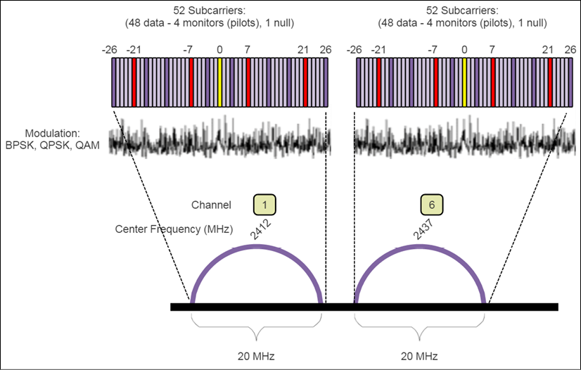
Figure 9: An example of OFDM. Here a channel is subdivided into 52 smaller slots or subcarriers (each carrying a symbol).
The set of different modulations available for each standard is called the Modulation and Coding Scheme (MCS). The MCS is a table of available modulation types, guard intervals, and coding rates. You reference this table with an index.
802.11b devices entered the market before 802.11a came to market. 802.11b uses a different encoding scheme than 802.11a. The encoding schemes are not compatible. Thus, there is some confusion in the market regarding the difference, as the protocols were released nearly simultaneously.
IEEE 802.11 MIMO
MIMO is the acronym that for multiple-input multiple-output. MIMO exploits a previously mentioned RF phenomenon called multipath. Multipath transmission implies that signals will reflect off walls, doors, windows, and other obstructions. A receiver will see many signals, all arriving at different times via different paths.
Multipath tends to distort signals and cause interference, which eventually degrades signal quality. (This effect is called multipath fading.) With the addition of multiple antennas, a MIMO system can linearly increase the capacity of a given channel by simply adding more antennas. There are two forms of MIMO:
- Spatial diversity: This refers to transmit-and-receive diversity. A single stream of data is transmitted on multiple antennas simultaneously using space-time coding. These provide improvements in the signal-to-noise ratio, and they are characterized by their improvement of link reliability and coverage of the system.
In the previous chapter, we introduced frequency-hopping techniques in PAN networks such as Bluetooth. Frequency hopping is one method to overcome the multipath fading problem by constantly changing the angles of the multipath. This has the effect of distorting the RF signal size. Bluetooth systems typically have one antenna, thereby making MIMO difficult. As far as Wi-Fi is concerned, only the original 802.11 standard supported a form of FHSS. OFDM systems maintain a channel lock and thus can be subject to the multipath fading problem.
Using multiple streams does impact overall power usage. IEEE 802.11n includes a mode to enable MIMO only when the effect will have a performance benefit, thus saving power at all other times. The Wi-Fi Alliance requires all products to support at least two spatial streams to receive 802.11n compliance.
- Spatial multiplexing: This is used to provide additional data capacity by utilizing the multiple paths to carry additional traffic—that is, increasing the data throughput capability. Essentially, a single high-rate data stream will be split into multiple separate transmissions on different antennas.
A WLAN will split data into multiple streams called spatial streams. Each transmitted spatial stream will use a different antenna on the transmitter. IEEE 802.11n allows for four antennas and four spatial streams. By using multiple streams sent separately for antennas spaced apart from each other, spatial diversity in 802.11n gives some confidence that at least one signal will be strong enough to reach the receiver. At least two antennas are needed to support MIMO functionality. Streaming is also modulation agnostic. BPSK, QAM, and other forms of modulation work with spatial streaming.
A digital signal processor on the transmitter and receiver will adjust for the multipath effects and delay the line-of-sight transmission by just enough time to have it line up perfectly with the non-line-of-sight paths. This will cause the signals to reinforce.
The IEEE 802.11n protocol supports a four-stream single user MIMO (SU-MIMO) implementation, meaning that the transmitters would work in unison to communicate to a single receiver. Here, four transmit and four receive antennas deliver multiple streams of data to a single client. The following is an illustration of SU-MIMO and multipath use in 802.11n:

Figure 10: Left: Illustration of SU-MIMO in IEEE 802.11n. Right: The effect of spatial diversity MIMO in 802.11n.
In the figure, four transmit and four receive antennas deliver multiple streams of data to a single client (SU-MIMO). On the right, two transmitters spaced a fixed distance apart communicate to two receivers. Multiple paths exist as reflections from the two transmitters. One line-of-sight path is stronger and will be favored. DSPs on the transmitters and receiver side also mitigate multipath fading by combining signals so the resulting signal exhibits little fading.
The IEEE 802.11 protocol identifies MIMO streams by the notation M × N : Z, where M is the maximum number of transmit antennas and N is the maximum number of receiver antennas. Z is the maximum number of data streams that can be used simultaneously. So, a MIMO of 3 × 2 : 2 implies there are three transmit stream antennas and two receive stream antennas, but can only send or receive two simultaneous streams.
802.11n also introduced the optional feature of beamforming. 80211.n defines two types of beamforming methods: implicit feedback and explicit feedback:
- Implicit feedback beamforming: This mode assumes that the channel between the beamformer (AP) and the beamformee (client) are reciprocal (the same quality in both directions). If that is true, the beamformer transmits a training request frame and receives a sounding packet. With the sounding packet, the beamformer can estimate the receiver's channel and build a steering matrix.
- Explicit feedback beamforming: In this mode, the beamformee responds to a training request by computing its own steering matrix and sends back the matrix to the beamformer. This is a more reliable method.
The following diagram illustrates the effects of beamforming in a situation with no line-of-sight communication. In the worst case, the signals arrive 180 degrees out of phase and nullify each other. With beamforming, the signals can be adjusted in phases to strengthen each other at the receiver.
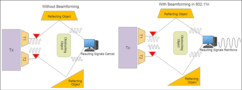
Figure 11: Examples of a system with and without beamforming. In this case, the system has no direct line of sight and relies on reflections to propagate a signal.
Beamforming relies on multiple spaced antennas to focus a signal at a particular location. The signals can be adjusted in phases and magnitudes to arrive at the same location and reinforce each other, providing better signal strength and range. Unfortunately, 802.11n did not standardize on a single method for beamforming and left that up to the implementor. Different manufacturers used different processes and could only guarantee it would work with identical hardware. Thus, beamforming was not adopted heavily in the 802.11n timeframe.
We will cover MIMO technologies in many other areas, such as 802.11ac, and in the next chapter, on long-range communication using cellular 4G LTE radios.
IEEE 802.11 packet structure
802.11 uses the typical packet structure we have seen before with headers, payload data, frame identifiers, and so on. Starting with the PHY frame organization, we have three fields: a preamble, which assists in the synchronization phase; a PLCP header, which describes the packet configuration and characteristics such as data rates; and the MPDC MAC data.
Each IEEE 802.11 specification has a unique preamble and is structured by the number of symbols (described later) and not by the number of bits for each field. Examples of the preamble structures are as follows:
- 802.11 a/g: Preamble includes a short training field (two symbols) and a long training field (two symbols). These are used by the subcarriers for timing sync and frequency estimation. Additionally, the preamble includes a signal field that describes the data rate, length, and parity. The signal determines how much data is being transmitted in that particular frame.
- 802.11 b: Preamble will use either a long sequence of 144 bits or a short sequence of 72 bits. The header will include signal rate, service modes, length of data in microseconds, and a CRC.
- 802.11n: Has two operating modes: Greenfield (HT) and mixed (non-HT). Greenfield can only be used where no legacy systems exist. Non-HT mode is a compatibility mode with 802.11a/g systems and delivers no better performance than a/g. Greenfield mode allows for higher speed transport.
The following illustration is the 802.11 PHY and link layer packet frame structure:
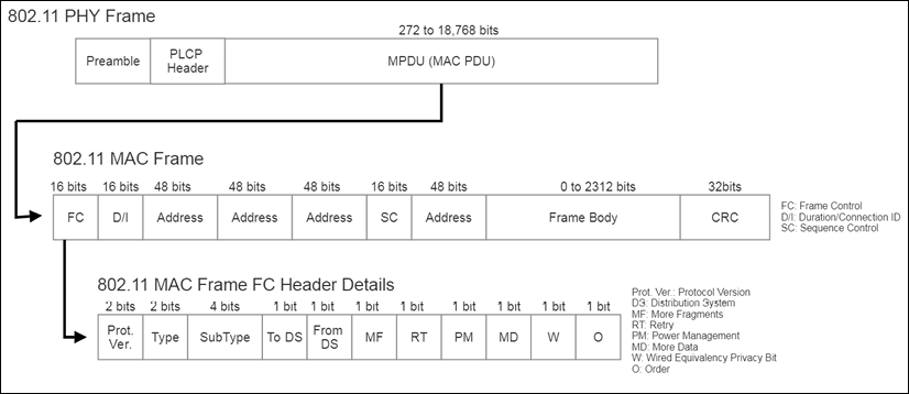
Figure 12: 802.11 generalized PHY and MAC frame structure
The MAC frame structure is shown in the preceding figure. The MAC frame contains the plurality of representative fields. The frame control (FC field) subfields are detailed as follows:
- Protocol version: This indicates the version of the protocol used.
- Type: This identifies the WLAN frame as control, data, or management frame type.
- Subtype: This provides further delineation of the frame type.
- ToDS and FromDS: Data frames will set one of these bits to 1 to indicate if the frame is headed to a distribution system. This is an IBSS ad hoc network.
- More fragments: If a packet is divided into many frames, then every frame except the last will have this bit-set.
- Retry: This indicates a frame was resent and assists in resolving duplicate frames being transmitted.
- Power management: This indicates the power state of the sender. APs cannot set this bit.
- More data: An AP will use this bit to assist when STAs are in a power-saving mode. This bit is used to buffer frames in a distribution system.
- Wired equivalent privacy: This is set to 1 when a frame is decrypted.
- Order: If a strict order mode is used in the network, this bit will be set. Frames may not be sent in order, and strict order mode forces in-order transmission.
Moving up the MAC frame from the frame control field, we first examine the duration/connection ID bit:
- Duration/connection ID: This indicates duration, contention-free period, and association ID. The association ID is registered during the Wi-Fi initial handshaking.
- Address fields: 802.11 can manage four addresses, which may include the following information:
- Destination address (DA)
- Source address (SA)
- Transmitting station address (TA)
- Receiving station address (RA)
- SC: Sequence control is a 16-bit field for message order.
The 802.11 protocol has several types of frames represented by the type and subtype fields. There are three fundamental types: management frames, control frames, and data frames.
Management frames provide network administration, security, and maintenance. The following table defines the types of management frames:
The next major frame type is the control frame. Control frames help exchange data between STAs:
The final frame type is the data frame. This is the bulk of the data-carrying function of the protocol.
IEEE 802.11 operation
As mentioned previously, an STA is considered a device equipped with a wireless network interface controller. An STA will always be listening for active communication in a specific channel. The first phase of connecting to Wi-Fi is the scanning phase. There are two types of scan mechanisms employed:
- Passive scanning: This form of scanning uses beacons and probe requests. After a channel is selected, the device performing the scan will receive beacons and probe requests from nearby STAs. An access point may transmit a beacon, and if the STA receives the transmission, it may progress to join the network.
- Active scanning: In this mode, the STA will attempt to locate an access point by instantiating probe requests. This mode of scanning uses more power but allows for faster network joins. The AP may respond to a probe request with a probe request response, which is similar to a beacon message.
Beacons are always broadcast at the lowest basic rates to ensure every STA in the range has the ability to receive the beacon even if it can't connect to that particular network. After a beacon is processed, the next phase of Wi-Fi connectivity is the synchronization phase. This phase is necessary to keep clients attuned to the access point. The beacon packet contains information needed by the STA:
- Service Set ID (SSID): A 1- to 32-character network name. This field can optionally be hidden by setting the SSID length to zero. Even if it is hidden,the other portions of the beacon frame are transmitted as usual. Generally speaking, using a hidden SSID offers no additional network security.
- Basic Service Set ID (BSSID): A unique 48-bit following layer-2 MAC address conventions. It is formed by the combination of the 24-bit organization unique identifier and the manufacturer's assigned 24-bit identifier for the radio chipset.
- Channel width: 20 MHz, 40 MHz, and so on.
- Country: List of supported channels (country-specific).
- Beacon interval: TBTT time mentioned previously.
- TIM/DTIM: Wake-up times and intervals to retrieve broadcast messages—allows for advanced power management.
- Security services: WEP, WPA, and WPA2 abilities.
Beacons are an interesting concept with a likeness to Bluetooth beacons. Bluetooth wireless offers much greater message capabilities and flexibility in beacon broadcasts, but there is a range of products and services that make use of Wi-Fi beaconing as well.
If the STA does find an AP or another STA to make a connection with, it then enters an authentication phase. More will be discussed on the variety of security standards used in 802.11 later in this chapter.
If the security and authentication process succeeds, the next phase is association. The device will send an association request frame to the AP. The AP will subsequently reply with an association response frame that will allow the STA to join the network or be excluded. If the STA is included, the AP will release an association ID to the client and add it to the list of connected clients.
At this point, data can be exchanged with the AP and vice versa. All data frames will be followed by an acknowledgment.
IEEE 802.11 security
In the previous section, we described the association process for a Wi-Fi device to join a network. One of the phases involved was authentication. This section will cover the various types of authentication used on Wi-Fi WLANs and various strengths and weaknesses:
- Wired equivalent privacy (WEP): The WEP mode sends a key in plain text from the client. The key is then encrypted and sent back to the client. WEP uses different size keys, but they are typically 128-bit or 256-bit. WEP uses a shared key, which means that the same key is available to all clients. It can be easily compromised by simply listening and sniffing for all the authentication frames coming back to clients joining a network to determine the key used for everyone. Due to a weakness in the key generation, the first few bytes of the pseudorandom string may reveal (5% probability) a portion of the key. By intercepting 5-10 million packets, an attacker could with reasonable confidence get enough information to reveal the key.
- Wi-Fi protected access (WPA): Wi-Fi protected access (or WPA-Enterprise) was developed as the IEEE 802.11i security standard to replace WEP and is a software/firmware solution requiring no new hardware. One significant difference is WPA uses a Temporal Key Integrity Protocol (TKIP), which performs per-packet key mixing and rekeying. This means that each packet will use a different key to encrypt itself, unlike in the case of WEP. WPA starts by generating a session key based on the MAC address, temporal session key, and the initialization vector. This is fairly processor-intensive but only performed once per session. The next step is to extract the lowest 16 bits of a received packet with the result of the bits generated in phase one. This is the 104-bit per-packet key. Data can now be encrypted.
- WPA pre-shared key (WPA-PSK): The WPA-PSK, or WPA-Personal, mode exists where there is no 802.11 authentication infrastructure. Here, one uses a passphrase as a pre-shared key. Each STA can have its own pre-shared key associated with its MAC address. This is similar to WEP, and weaknesses have already been found if the pre-shared key uses a weak passphrase.
- WPA2: This replaces the original WPA design. WPA2 uses AES for encryption, which is much stronger than TKIP in WPA. This encryption is also called CTR mode with CBC-MAC Protocol, or CCMP for short.
To achieve high bandwidth rates in 802.11n, CCMP mode must be used, or the data rate will not exceed 54 Mbps. Additionally, WPA2 certification is needed to use the Wi-Fi Alliance trademark logo.
IEEE 802.11ac
IEEE802.11ac is the next-generation WLAN and the follow-on to the family of 802.11 standards. IEEE802.11ac was approved as a standard in December 2013 after five years of work. The goal is to deliver multistation throughput of at least 1 GBps and a single link throughput of 500 Mbps. The technology accomplishes this through wider channel bandwidth (160 MHz), more MIMO spatial streams, and extreme density modulation (256-QAM). 802.11ac exists only in the 5 GHz band, yet will coexist with previous standards (IEEE802.11a/n).
The specifics of and differences between IEEE802.11ac and IEEE802.11n are:
- 80 MHz channel width minimum with 160 MHz maximum channel width
- Eight MIMO spatial streams:
- Introduced downlink MU-MIMO with up to four downlink clients
- Multiple STAs with multiple antennas can now transmit and receive independently on multiple streams
- 256-QAM optional modulation with the ability to use 1024-WAM standardized beamforming
Multiuser MIMO is worth further details. 802.11ac extends 802.11n from four spatial streams to eight. One of the largest contributing factors to 802.11ac speed is spatial division multiplexing (SDM), referred to earlier. When combined with multiuser or multiple client aspects of 802.11ac, this technique goes by the name space-division multiple access (SDMA). Essentially, MU-MIMO in 802.11ac is a wireless analog of a network switch. The following illustration depicts an 802.11ac 4 × 4: 4 MU-MIMO system with three clients:
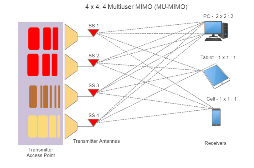
Figure 13: 802.11ac MU-MIMO usage
802.11.ac also extends the modulation constellation from 64-QAM to 256-WAM. This implies there are 16 amplitude levels and 16 phase angles, requiring very precise hardware to implement. 802.11n represented six bits per symbol, while 802.11ac represents a full eight bits per symbol.
Beamforming methods have been formally standardized by the IEEE committee. For example, the committee has agreed that explicit feedback is the standard approach to beamforming association. This will allow beamforming and the performance benefits to be available from multiple vendors.
The increased bandwidth per channel (up to 80 MHz with the option of 160 MHz or two 80 MHz blocks) provides a substantial increase in throughput in the 5 GHz space.
Theoretically, using an 8 × 8: 8 device, 160 MHz wide channels, and 256-QAM modulation, one could sustain 6.933 GBps throughput in aggregate.
IEEE 802.11p vehicle-to-vehicle
Vehicular networks (sometimes called vehicular ad hoc networks or VANET) are spontaneous and unstructured, operating like a car moves around a city while interacting with other vehicles and infrastructure. This model of network makes use of vehicle-to-vehicle (V2V) and vehicle-to-infrastructure (V2I) models.
In 2004, the 802.11p task group formed and developed the first draft by April 2010. 802.11p is considered a dedicated short-range communication (DSRC) channel within the US Department of Transportation. The goal of this network is to provide a standard and secure V2V and V2I system used for vehicular safety, toll collection, traffic status/warnings, roadside assistance, and e-commerce within a vehicle.
The topology and general use case for an IEEE 802.11p network is shown in the following figure. There are two types of nodes in the network. First is the road-side unit (RSU), which is a fixed location device much like an access point. It serves to bridge vehicles and moving devices to the Internet for application service usage and access to trust authorities. The other node type is the on-board unit (OBU), which resides in the vehicle. It is able to communicate with other OBUs and the fixed RSUs when needed.
OBUs can communicate with RSUs and each other to relay vehicle and safety data. RSUs are used to bridge to application services and trust authorities for authentication. The following is an example 802.11p usage and topology:

Figure 14: IEEE 802.11p use case: OBUs within vehicles and fixed infrastructure RSUs
For transportation systems, several challenges exist in wireless communication. There is a heightened level of safety necessary in vehicular communication and control. Physical effects such as Doppler shifts, latency effects, and robust ad hoc networking are a few issues to consider.
Many of the differences from the 802.11 standards are to ensure quality and range over the speed of transmission. Other factors are changes to reduce the latency in starting up a connection. The following is a summary of the features of IEEE 802.11p and differences from the IEEE 802.11a standards:
- Channel width is 10 MHz instead of the 20 MHz used in 802.11a.
- IEEE 802.11p operates in the 75 MHz bandwidth of the 5.9 GHz space. This implies there is a total of seven channels available (one control, two critical, and four service channels).
- It supports half as many bit rates as 802.11a—that is, 3/4.5/6/9/12/18/24/27 Mbps.
- It has the same modulation schemes, such as BPSK/QPSK/16QAM/64QAM and 52 subcarriers.
- The symbol duration has become double that of 802.11a: IEEE 802.11p supports 8 µs, while 11a supports 4µs.
- Guard time interval is 1.6µs in 802.11p, while 11a has 0.8µs.
- Techniques such as MIMO and beamforming are not necessary or part of the specification.
The 75 MHz channels are categorized as follows:
| Channel |
172 |
174 |
176 |
178 |
180 |
182 |
184 |
| Center frequency (GHz) |
5.860 |
5.870 |
5.880 |
5.890 |
5.900 |
5.910 |
5.920 |
| Purpose |
Critical life safety |
Service |
Service |
Control |
Service |
Service |
High power public safety |
The fundamental usage model of 802.11p is to create and associate to ad hoc networks rapidly. This link will come and go as vehicles move away from each other and other vehicles eventually reconstitute the fabric. In the standard 802.11 model, a BSS would be the network topology to use, which requires the synchronization, association, and authentication for a wireless network to form. 802.11p provides a wildcard BSSID in the header of all frames exchanged and allows links to start exchanging data frames immediately after arriving on a communication channel.
The IEEE 802.11p protocol stack is derived from 802.11a but makes important changes to address vehicular safety and security. The following figure depicts the protocol stack. A significant departure from other IEEE 802.11 stacks is the use of the IEEE 1609.x standards to address application and security models. The full stack is called wireless access in vehicular environments (WAVE) and combines 802.11p PHY and MAC layers with IEEE 1609.x layers:

Figure 15: The 802.11p Automotive Protocol Stack
Specific differences to highlight in the stack include:
- 1609.1: WAVE resource manager. It allocates and provisions resources as needed.
- 1609.2: Defines security services for application and management messages. This layer also provides two modes of encryption. A public-key algorithm using the signing algorithm ECDSA can be used. Alternatively, a symmetric algorithm based on AES-128 in CCM mode is available.
- 1609.3: Assists with connection setup and management of WAVE-compliant devices.
- 1609.4: Provides multichannel operation above the 802.11p MAC layer.
Security is critical in a VANET. There are potential threats that can directly affect public safety. Attacks can occur where bogus information is broadcast, affecting how other vehicles react or perform. An attack of this nature could be a rogue device broadcasting a hazard in a road and causing vehicles to hard stop. Security also needs to account for private vehicular data, masquerading as other vehicles and causing a denial of services attack. All these can lead to catastrophic events and need standards such as the IEEE 1609.2.
IEEE 802.11ah
Based on 802.11ac architecture and PHY, 802.11ah is a variant of the wireless protocols targeted for the IoT. The design attempts to optimize for constrained sensor devices that require long battery life and can optimize range and bandwidth. 802.11ah is also referred to as HaLow, which is essentially a play on words with "ha" referring to "ah" backward and "low" implying low power and lower frequency. Put together, it forms a derivative of "hello."
The intent of the IEEE 802.11ah task group was to create a protocol with extended range for rural communications and offloading cell traffic. The secondary purpose was to use the protocol for low-throughput wireless communications in the sub-gigahertz range. The specification was published on December 31, 2016. The architecture is most different from other forms of 802.11 standards in the following ways in particular:
- Operates in the 900 MHz spectrum. This allows for good propagation and penetration of materials and atmospheric conditions.
- Channel width varies and can be set to 2, 4, 8, or 16 MHz-wide channels. The available modulation methods are diverse and include BPSK, QPSK, 16-QAM, 64-WAM, and 256-QAM modulation techniques.
- Modulation based on the 802.11ac standard with specific changes. A total of 56 OFDM subcarriers with 52 dedicated to data and 4 dedicated to pilot tones. Total symbol duration is 36 or 40 microseconds.
- Supports SU-MIMO beamforming.
- Fast association for networks of thousands of STAs using two different authentication methods to limit contention.
- Provides connectivity to thousands of devices under a single access point. It includes the ability to relay to reduce power on STAs and allow for a crude form of mesh networking using a one-hop reach method.
- Allows for advanced power management on each 802.11ah node.
- Allows for non-star topology communication through the use of restricted access windows (RAW).
- Allows for sectorization, which enables antennas to be grouped to cover different regions of a BSS (called sectors). This is accomplished using beamforming adopted from other 802.11 protocols.
The minimum throughput will be 150 Kbps, based on BPSK modulation on a single MIMO stream at 1 MHz channel bandwidth. The maximum theoretical throughput will be 347 Mbps based on a 256-WAM modulation using 4 MIMO streams and 16 MHz channels.
The IEEE 802.11ah specification requires that STAs support 1 MHz and 2 GHz channel bandwidths. The access points must support 1, 2, and 4 MHz channels. 8 MHz and 16 MHz channels are optional. The narrower the channel bandwidth is, the longer the range but the slower the throughput.
The wider the channel bandwidth is, the shorter the range but the faster the throughput.
Channel width will vary depending on the region in which 802.11ah is deployed. Some combinations will not work due to regulations in specific regions, as shown:

Figure 16: Left: Different channelization options depending on regional regulations. Right: Varying bandwidth options and channel bonding within the US region from 1 MHz to 16 MHz channels.
Every attempt in the architecture of the IEEE 802.11ah standard is aimed at optimizing overall range and efficiency. This reaches down as far as the length of the MAC headers.
The goal to connect several thousand devices to a single AP is also accomplished using a unique association identifier (AID) assignment of 13 bits. This allows the grouping of STAs based on criteria (hallway lights, light switch, and so on). This allows an AP to connect to over 8191 STAs. (802.11 could support only 2007 STAs.) That many nodes, however, has the potential to induce a massive number of channel collisions. Even though the number of connected STAs increased, the goal was to reduce the amount of data in transit to address these stations.
The IEEE task group accomplished this by removing a number of fields that were not particularly relevant for the IoT use cases, such as the QoS and DS fields. The following figure illustrates the 802.11ah MAC downlink and uplink frames as compared to standard 802.11.

Figure 17: A comparison of the standard 802.11 MAC frame and 802.11ah condensed frames
Another improvement for power management and channel efficiency is attributed to removing acknowledgment frames. ACKs are implicit for bidirectional data. That is, both devices are sending and receiving data from each other. Normally, an ACK would be used after the successful reception of a packet. In this bidirectional transport (BDT) mode, reception of the next frame implies that the previous data was successfully received and no ACK packet needs to be exchanged.
To avoid a sea of collisions, which would prevent a functional network, 802.11ah uses a RAW. As the STAs are divided into various groups using the AID, channels will be split into time slots. Each group will be assigned a specific time slot and no others. There are exceptions, but for the general case, the grouping forms an arbitrary isolation. The additional benefit of RAW is that devices can enter a hibernation state to conserve power whenever it isn't their time slot for transmission.
Topology-wise, there are three types of stations in an 802.11ah network:
- Root access point: The principal root. Typically, it serves as a gateway to other networks (WAN).
- STA: The typical 802.11 station or endpoint client.
- Relay node: A special node that combines an AP interface to STAs residing on a lower BSS and an STA interface to other relay nodes or a root AP on the upper BSS.
The following figure is the IEEE802.11ah topology. This architecture differs substantially from other 802.11 protocols in the use of single-hop relay nodes that act to create an identifiable BSS. The hierarchy of relays forms a larger network. Each relay acts as an AP and STA:

Figure 18: IEEE802.11ah network topology
In addition to the basic node types, there are three power-saving states an STA can reside in:
- Traffic indication map (TIM): Listens to AP for data transfer. Nodes will periodically receive information about data buffered for them from its access point. The message sent is called the TIM information element.
- Non-TIM stations: Negotiates with AP directly during association to obtain transmission time on Periodic Restricted Access Windows (PRAW).
- Unscheduled stations: Does not listen to any beacons and uses polling to access channels.
Power is critical in IoT sensor and edge devices based on coin cell batteries or energy harvesting. 802.11 protocols are notorious for high power demands. To remediate the power of this wireless protocol, 802.11ah uses a Max Idle Period value, which is part of the regular 802.11 specifications. In a general 802.11 network, the Max Idle Period is roughly 16 hours based on a time of 16-bit resolution. In 802.11ah, the first two bits of the 16-bit timer are a scaling factor that allows the sleep duration to exceed five years.
Additional power is mitigated through changes to the beacon. As previously covered, beacons relay information on the availability of buffered frames. Beacons will carry a TIM bitmap, which inflates their size since 8191 STAs will cause the bitmap to grow substantially. 802.11ah uses a concept called TIM segmentation where some beacons carry portions of the overall bitmap. Each STA calculates when their respective beacon with bitmap information will arrive and allows the device to enter a power-saving mode until the moment it needs to wake and receive beacon information.
Another power-saving feature is called the Target Wake Time (TWT), which is intended for STAs that rarely transmit or receive data. This is very common in IoT deployments such as temperature sensor data. An STA and its associated AP will negotiate to arrive at an agreed upon TWT, and the STA will enter a sleep state until that timer is signaled.
The process of implicit ACKs is called a Speed Frame Exchange, and it is shown in the following figure:

Figure 19: IEEE 802.11ah Speed Frame Exchange: An example of Target Wake Time (TWT) used to start an STA communicating. SIFS represents the gap between the AP and STA communicating. No ACKs are used between data pairs. Only a single ACK at the end of transmission is sent before the STA returns to a sleep mode.
6LoWPAN topologies
6LoWPAN networks are mesh networks residing on the periphery of larger networks. The topologies are flexible, allowing for ad hoc and disjointed networks without any binding to the Internet or other systems, or they can be connected to the backbone or the Internet using edge routers. 6LoWPAN networks can be conjoined with multiple edge routers; this is called multihoming. Additionally, ad hoc networks can form without requiring the Internet connectivity of an edge router.
These topologies are shown in the following figure:

Figure 20: 6LoWPAN topologies
An edge router (also known as a border router) is necessary for a 6LoWPAN architecture as it has four functions:
- Handles the communication to the 6LoWPAN devices and relays data to the Internet.
- Performs compression of IPv6 headers by reducing a 40-byte IPv6 header and 8-byte UDP headers for efficiency in a sensor network. A typical 40-byte IPv6 header can compress to 2 to 20 bytes depending on usage.
- Initiates the 6LoWPAN network.
- Exchanges data between devices on the 6LoWPAN network.
Edge routers form 6LoWPAN mesh networks on larger traditional network perimeters. They can also broker exchanges between IPV6 and IPV4 if necessary. Datagrams are handled in a similar manner as in an IP network, which has some advantages over proprietary protocols. All nodes within a 6LoWPAN network share the same IPv6 prefix that the edge router establishes. Nodes will register with the edge routers as part of the Network Discovery (ND) phase.
ND controls how hosts and routers in the local 6LoWPAN mesh will interact with each other. Multihoming allows for multiple 6LoWPAN edge routers to manage a network—for example, when there is a need for multiple media (4G and Wi-Fi) for failover or fault tolerance.
There are three types of nodes within the 6LoWPAN mesh:
- Router nodes: These nodes marshal data from one 6LoWPAN mesh node to another. Routers can also communicate outward to the WAN and Internet.
- Host nodes: Hosts in the mesh network cannot route data in the mesh and are simply endpoints consuming or producing data. Hosts are allowed to be in sleep states, occasionally waking to produce data or receive data cached by their parent routers.
- Edge routers: As stated, these are the gateways and mesh controllers usually at a WAN edge. A 6LoWPAN mesh would be administered under the edge router.
Nodes are free to move and reorganize/reassemble in a mesh. For that matter, a node can move and associate with a different edge router in a multihome scenario or even move between different 6LoWPAN meshes. These changes to the topology can be caused for various reasons, such as changes in signal strength or the physical movement of nodes. When a topology change occurs, the IPv6 address of the associated nodes will also naturally change.
In an ad hoc mesh without an edge router, a 6LoWPAN router node could manage a 6LoWPAN mesh. This would be the case when WAN connectivity to the Internet is not necessary. Typically, this is seldom seen as IPv6 addressability for a small ad hoc network isn't necessary.
The router node would be configured to support two mandatory functions:
- Unique local unicast address generation
- Performing neighbor discovery ND registration
The ad hoc mesh IPv6 prefix would be a local prefix rather than the larger global WAN IPv6 prefix.
6LoWPAN protocol stack
To enable 6LoWPAN on a form of communication media such as 802.15.4, there is a set of recommended features necessary to support an IP protocol. These features include framing, unicast transmission, and addressing. As shown in the following figure, the physical layer is responsible for receiving and converting data bits over the air. For this example, the link layer we speak to is IEEE 802.15.4. On top of the physical layer is the data link layer, responsible for detecting and correcting errors on the physical link. Detailed information on the physical and data link layer of 802.15.4 are covered earlier in this chapter. Here is the comparison between the 6LoWPAN stack and the OSI model:

Figure 21: 6LoWPAN protocol stack compared with the simplified OSI model. 6LoWPAN resides on top of other protocols like 802.15.4 or Bluetooth to provide the physical and MAC address.
By enabling IP traffic at a sensor level, the relationship between the device and the gateway would use some form of application layer to convert data from the non-IP protocol to an IP protocol. Bluetooth, Zigbee, and Z-Wave all have some form of conversion from their base protocol to something that can communicate over IP (if the intent is to route the data). The edge routers forward datagrams at a network layer. Because of this, the router does not need to maintain an application state. If an application protocol changes, a 6LoWPAN gateway doesn't care.
If an application protocol changes for one of the non-IP protocols, the gateway will need to change its application logic as well. 6LoWPAN provides an adaptation layer within layer three (the network layer) and on top of layer two (the data link layer). This adaptation layer is defined by the IETF.
Mesh addressing and routing
Mesh routing operates in the physical and data link layers to allow packets to flow through a dynamic mesh using multiple hops. We previously talked about mesh-under and route-over routing, but we will go somewhat deeper in this section into that form of routing.
6LoWPAN mesh networks utilize two schemes for routing:
- Mesh-under network: In a mesh-under topology, routing is transparent and assumes a single IP subnet representing the entirety of the mesh. A message is broadcast in a single domain and sent to all devices in the mesh. As previously mentioned, this generates considerable traffic. Mesh-under routing will move from hop to hop in the mesh but only forward packets up to layer two (the data link layer) of the stack. 802.15.4 handles all the routing for each hop in layer two.
- Route-over network: In a route-over topology, networks will incur the charge of forwarding packets up to layer three (the network layer) of the stack. Route-over schemes manage routes at an IP level. Each hop represents one IP router.
The following graphic depicts the difference between mesh-under and route-over routing:

Figure 22: The difference between mesh-under and route-over networking. The intermediary hops reveal how far up each stack the packet is delivered before moving to the next node in the mesh.
A route-over network implies that every router node is equally capable and can perform the larger set of functions as a normal IP router, such as duplicate address detection. RFC6550 formally defines the route-over protocol RPL (ripple). The advantage of the route-over architecture is the similarity with traditional TCP/IP communication. RPL provides multipoint-to-point communication (where traffic from devices in a mesh communicate to a central server on the Internet) and point-to-multipoint communication (central service to the devices in the mesh).
The RPL protocol has two modes for managing the route tables:
- Storing mode: All devices configured as routers in a 6LoWPAN mesh maintain routing and neighbor tables.
- Non-storing mode: Only a single device, such as the edge router, maintains the routing and neighbor tables. To transmit data from one host to another in a 6LoWPAN mesh, the data is sent up to the router where its route is calculated then transmitted to the receiver.
The routing table, as the name implies, contains the mesh routing paths, while the neighbor table maintains each node's directly connected neighbors. This implies that the edge router will always be referenced to deliver packets in the mesh. This allows the router nodes the freedom of not managing large routing tables, but it will add latency in moving packets since the edge router must be referenced. Storing mode systems will have higher processing and memory requirements to manage routing tables stored on each node, but will have a more efficient path to establishing a route.
Note in the following figure the hop count, source address, and destination address fields. These fields are used during the address resolution and routing phase. The hop count is set to an initial high value and then decremented each time the packet propagates from node to node in the mesh. The intent is when the hop limit reaches zero, the packet is dropped and lost from the mesh. This provides a way to prevent runaway networks if a host node removes itself from the mesh and is no longer reachable. The source and destination address are 802.15.4 addresses and may be in short or extended format, as 802.15.4 allows. The header is constructed as follows:

Figure 23: 6LoWPAN mesh addressing header
Header compression and fragmentation
While the advantage of having virtually unlimited IP addresses for things is a significant milestone, placing IPv6 on an 802.15.4 link poses some challenges that must be overcome to make 6LoWPAN usable. First is the fact that IPv6 has a maximum transmission unit (MTU) size of 1,280 bytes, while 802.15.4 has a limit of 127 bytes. The second issue is that IPv6 in general adds significant girth to an already bloated protocol. For example, in IPv6 headers are 40 bytes long.
Note that IEEE 802.15.4g does not have a limitation of 127 bytes for a frame length.
Similar to IPv4, MTU path discovery in IPv6 allows a host to dynamically discover and adjust to differences in the MTU size of every link along a given data path. In IPv6, however, fragmentation is handled by the source of a packet when the path MTU of one link along a given data path is not large enough to accommodate the size of the packets. Having IPv6 hosts handle packet fragmentation saves IPv6 device processing resources and helps IPv6 networks run more efficiently. However, IPv6 requires that every link on the Internet has an MTU of 1,280 octets or greater. (This is what is known indeed as the IPv6 minimum link MTU.) On any link that cannot convey a 1,280-octet packet in one piece, link-specific fragmentation and reassembly must be provided at a layer below IPv6.
Header compression is a means to compress and remove redundancy in the IPv6 standard header for efficiency reasons. Normally, header compression is status-based, meaning in a network with static links and stable connections, it works reasonably well. In a mesh network such as 6LoWPAN, this will not work. Packets hop between nodes and require compression/decompression on each traverse. Additionally, the routes are dynamic and allowed to change, and transmissions may not be present for long durations. Therefore, 6LoWPAN adopted stateless and shared-context compression.
The type of compression can be affected by whether certain specifications are met, such as using RFC4944 over RFC6922, as well as where the source and destination of a packet reside, shown as follows:

Figure 24: Header compression in 6LoWPAN
The three cases of header compression for 6LoWPAN are based on whether the route is within the local mesh, outside of the mesh but to a known address, or outside of the mesh to an unknown address. Compared to standard IPv6 with a 40-byte header, 6 LoWPAN can compress to between 2 and 20 bytes.
Case one (in the preceding figure) is the best-case communication between nodes in a local mesh. No data is sent outward to the WAN with this compressed header format. The second case implies data is sent outward to the WAN to a known address, and the last case is similar but to an address that is unknown. Even in the third case, which is the worst case, compression still accounts for a 50 percent reduction in traffic. 6LoWPAN also allows for UDP compression, which is beyond the scope of this book.
Fragmentation is a secondary issue because MTU sizes are incompatible between 802.15.4 (127 bytes) and IPv6 at 1,280 bytes. The fragmentation system will divide each IPv6 frame into smaller segments. On the receiving side, the fragments will be reassembled. Fragmentation will differ depending on the type of routing elected during mesh configuration (we will discuss mesh-under and route–over routing later). The types of fragmentation and constraints are given as:
- Mesh-under routing fragmentation: Fragments will be reassembled only at the final destination. All fragments need to be accounted for during reassembly. If any are missing, the entire packet needs retransmission. As a side note, mesh-under systems require all fragments to be transmitted immediately. This will generate a burst of traffic.
- Route-over routing fragmentation: Fragments will be reassembled at every hop in the mesh. Each node along the route carries enough resources and information to rebuild all fragments.
The fragmentation header includes a Datagram Size field, which specifies the total size of the unfragmented data. The Datagram Tag field identifies the set of fragments belonging to a payload, and the Datagram Offset indicates where the fragment belongs in a payload sequence. Note the datagram offset is not used for the first fragment sent, as the offset of a new fragment sequence should start at zero.

Figure 25: 6LoWPAN fragmentation header
Fragmentation is a resource-heavy task that demands processing and energy ability that can tax a battery-based sensor node. It is advisable to limit the data sizes (at an application level) and use header compression to reduce the power and resource constraints in a large mesh.
Neighbor discovery
Neighbor discovery (ND) is defined by RFC4861 as a one-hop routing protocol. This is a formal contract between neighbor nodes in the mesh and allows nodes to communicate with each other. ND is the process of discovering new neighbors, as a mesh can grow, shrink, and transform, resulting in new and changing neighbor relations. There are two basic processes and four basic message types in ND:
- Finding neighbors: This includes Neighbor Registration (NR) and Neighbor Confirmation (NC) phases.
- Finding routers: This includes Router Solicitation (RS) and Router Advertisement (RA) phases.
During ND, there can be conflicts that arise. For example, if a host node disassociates from a router and establishes a link with a different router in the same mesh. ND is required to find duplicate addresses and unreachable neighbors as part of the specification. DHCPv6 can be used in conjunction with ND.
After an 802.15.4-capable device has bootstrapped through the physical and data link layers, 6LoWPAN can perform neighbor discovery and grow the mesh. This process will proceed as follows and as shown in the subsequent figure:
- Finding an appropriate link and subnet for low-power wireless.
- Minimizing node-initiated control traffic.
- The host sending out an RS message to request the mesh network prefix.
- The router responding with a prefix.
- The host assigning itself a link-local unicast address (FE80::IID).
- The host transmitting this link-local unicast address in an NR message to the mesh.
- Performing duplicate address detection (DAD) by waiting for an NC for a set time. If the timeout expires, it assumes the address is unused.

Figure 26: A simplified neighbor discovery sequence from a 6LoWPAN mesh node through a mesh router to the edge router and then off to the wide area network
After the host is configured, it can begin communicating over the Internet with a unique IPv6 address.
If mesh-under routing is used, the link-local address retrieved in step five can be used to communicate to any other node in the 6LoWPAN mesh. In a route-over scheme, the link-local address can be used to communicate only with nodes that are a single hop away. Anything greater than one hop will require a full routable address.
6LoWPAN security
Since, in a WPAN system, it is easy to sniff and overhear communication, 6LoWPAN provides security at multiple levels. At the 802.15.4 level two of the protocol, 6LoWPAN relies on AES-128 encryption of data. Additionally, 802.15.4 provides a counter with CBC-MAC mode (CCM) to provide encryption and an integrity check. Most chipsets that provide an 802.15.4 network block also include a hardware encryption engine for performance improvement.
At layer three (the network layer) of the protocol, 6LoWPAN has the option to use IPsec standard security (RFC4301). This includes:
- Authentication Handler (AH): As defined in RFC4302 for integrity protection and authentication
- Encapsulating Security Payload (ESP): In RFC4303, adds encryption to secure confidentiality in packets
ESP is by far the most common layer-three secure packet format. Additionally, a mode of ESP defines reusing AES/CCM used in layer-two hardware for layer-three encryption as well (RFC4309). This makes layer-three security suitable for constrained 6LoWPAN nodes.
In addition to link-layer security, 6LoWPAN also utilizes Transport Layer Security (TLS) for TCP traffic and Datagram Transport Layer Security (DTLS) for UDP traffic.
WPAN with IP – Thread
Thread is a relatively new networking protocol for IoT and is based on IPV6 (6LoWPAN). Its principal target is home connectivity and home automation. Thread was launched in July of 2014 with the formation of the Thread Group Alliance, which includes companies such as Alphabet (Google's holding company), Qualcomm, Samsung, ARM, Silicon Labs, Yale (locks), and Tyco.
Based on the IEEE 802.15.4 protocol and 6LoWPAN, it has commonality with Zigbee and other 802.15.4 variants, but with a significant difference being Thread is IP addressable. This IP protocol builds on the data and physical layers provided by 802.15.4 and features such as security and routing from 6LoWPAN. Thread is also mesh-based, making it attractive for home lighting systems with up to 250 devices in a single mesh. The philosophy with Thread is that by enabling IP addressability in the smallest of sensors and home automation systems, one can reduce power consumption and cost because the Thread-enabled sensor doesn't need to persist the application state in storage. Thread is based on datagrams at the network layer which, by its very nature, eliminates the need to process application layer information – saving system power.
Finally, being IPV6 compliant provides security options through encryption using the Advanced Encryption Standard (AES). Up to 250 nodes can exist on a Thread mesh all with fully encrypted transport and authentication. A software upgrade allows a preexisting 802.15.4 device to be Thread compatible.
Thread architecture and topology
Based on the IEEE 802.15.4-2006 standard, Thread uses the specification to define the Medium Access Control (MAC) and physical (PHY) layers. It operates at 250 Kbps in the GHz band.
From a topology point of view, Thread establishes communications with other devices through a border router (usually a Wi-Fi signal in a household). The rest of the communication is based on 802.15.4 and forms a self-healing mesh. An example of such a topology is shown as follows:

Figure 27: Example Thread network topology containing border routers, Thread routers, lead devices, and eligible IoT devices that can combine in the mesh. Interconnections are variable and self-healing.
The following are the roles of various devices in a Thread architecture:
- Border router: A border router is essentially a gateway. In the home network, this would be a communications crossover from Wi-Fi to Thread and would form the entry point to the Internet from a Thread mesh running underneath a border router. Multiple border routers are allowable under the Thread specification.
- Lead device: The lead device manages a registry of assigned router IDs. The lead also controls the requests for Router-Eligible End Devices (REED) to be promoted to routers. A leader can also act as a router and have device-end children. The protocol for the assignment of router addresses is the Constrained Application Protocol (CoAP). The state information a lead device manages can also be stored in the other Thread routers. This allows self-healing and failover if the leader loses connectivity.
- Thread routers: Thread routers manage the routing services of the mesh. Thread routers never enter a sleep state but are allowed by the specification to downgrade themselves to become a REED.
- REEDs: A host device that is a REED can become a router or a leader. REEDs are not responsible for routing in the mesh unless they are promoted to a router or leader. REEDs also cannot relay messages or join devices to the mesh. REEDs essentially are endpoints or leaf nodes in the network.
- End devices: Some endpoints cannot become routers. These types of REEDs have two other categories that they can subscribe to: full end devices (FEDs) and minimal end devices (MEDs).
- Sleepy end devices: Host devices that have entered a sleep state communicate only with their associated Thread router and cannot relay messages.
The Thread protocol stack
Thread makes use of the full benefits of 6LoWPAN and enjoys the benefits of header compression, IPv6 addressing, and security. Thread also uses the fragmentation scheme of 6LoWPAN as described in the previous section, but adds two additional stack components:
- Distance vector routing
- Mesh link establishment

Figure 28: Thread protocol stack
Thread routing
Thread uses route-over routing, as described in the previous section, on 6LoWPAN routing. Up to 32 active routers are allowed in a Thread network. Route traversal is based on next-hop routing. The master route table is maintained by the stack. All routers have an up-to-date copy of the routing for the network.
Mesh link establishment (MLE) is a method to update path traversal costs from one router to another in a network. Additionally, MLE provides a way to identify and configure neighboring nodes in the mesh and secure them. As a mesh network can expand, shrink, and change shape dynamically, MLE provides the mechanism to reconstitute the topology. MLE exchanges the path costs with all other routers in a compressed format. MLE messages will flood the network in a broadcast manner by the Multicast Protocol for Low-Power and Lossy Networks (MPL).
Typical 802.15.4 networks use on-demand route discovery. This can be costly (bandwidth due to route discovery flooding the network), and Thread attempts to avoid that scheme. Periodically, a Thread network router will exchange MLE advertisement packets with link cost information to its neighbors, essentially forcing all routers to have a current path list. If a route terminates (the host leaves the Thread network), then the routers will attempt to find the next best path to a destination.
Thread also measures link quality. Remember that 802.15.4 is a WPAN, and signal strength may change dynamically. Link quality is measured by the link cost of incoming messages for a neighbor with a value of zero (unknown cost) to three (good quality). The following table summarizes the quality to cost relation. Quality and cost are continually monitored and, as mentioned, periodically broadcast to the network for self-healing:
| Link quality | Link cost |
|
0 |
Unknown |
|
1 |
6 |
|
2 |
2 |
|
3 |
1 |
Thread addressing
To determine the route to a child node, a 16-bit short address is used. The low-order bits determine the child address and the high-order bits determine the parent. In the case the node is a router, the low-order bits are set to zero. At this point, the source of transmission knows the cost to reach the child as well as the next-hop information to start the route.
Distance vector routing is used to find paths to routers in the Thread network. The upper 6 bits of the 16-bit address indicate the destination router—this is the prefix. If the lower 10 bits of the destination are set to 0, then the final destination is that router. Alternatively, the destination router will forward the packet based on the lower 10 bits:

Figure 29: 2-byte Thread short address per 802.15.4-2006 specification
If a route extends outside of the Thread network, then a border router will signal to leaders of the particular prefix address information, such as the original prefix data, 6LoWPAN context, border routers, and the DHCPv6 server. This information is communicated via MLE packets through the Thread network.
Within the Thread network, all addressing is UDP-based. If a retry is necessary, then the Thread network will rely on:
- MAC-level retries: Where each device using MAC acknowledgments is an ACK that is not received from the next hop
- Application retries: Where the application layer will provide its own retry mechanism
Neighbor discovery
ND in Thread decides which 802.15.4 network to join. The process is as follows:
- The joining device contacts the router for commissioning.
- The joining device scans all channels and issues a beacon request on each channel. It waits for a beacon response.
- If a beacon containing the payload with the network service set identifier (SSID) and permit-joining message is seen, the device will join the Thread network.
- Once a device is discovered, MLE messages will be broadcast to identify a neighbor router to the device. That router will perform commissioning. There are two commissioning modes:
- Configuring: Uses an out-of-band method to commission a device. Allows a device to attach to the Thread network as soon as it is introduced to the network.
- Establishing: Creates a commissioning session between the device and a commissioned application that is running on a smartphone or tablet or is web-based.
- The device that is joining contacts the parent router and joins the network via MLE exchange.
The device will exist as either a REED or an end device and is allocated a 16-bit short address by the parent.
Summary
This chapter covered a necessary portion of IoT communication. Using IP-based standard communication greatly simplifies design and allows for rapid and easy scaling. Scaling is critical for IoT deployments that reach into thousands or millions of nodes. Using IP-based transport allows for common tools to simply just work. 6LoWPAN and Thread demonstrate standards that can be applied to traditionally non-IP protocols such as 802.15.4. Both protocols allow for IPv6 addressing and mesh networking to massive IoT networks. 802.11 is a significant and extremely successful protocol that forms the basis of the WLAN but can also reach into IoT devices and sensors using 802.11ah or transportation systems using 802.11p. The following table contrasts a non-IP traditional protocol with an IP protocol. Typically, the difference will be in power, speed, and range.
The architect needs to balance these parameters to deploy the correct solution:
| 802.15.4 | 802.11ah | |
|
IP base |
Non-IP based (needs 6LoWPAN or Thread) |
IP-based |
|
Range |
100 m |
Targeted to 1,000 m |
|
Network structure |
Full mesh |
Hierarchical with a single node hop |
|
Channelization |
ISM 2.4 GHz with only DSSS |
Sub 1 GHz ISM with various modulation coding schemes. Channel bandwidth: 1,2, 4, 8, 16 MHz |
|
Channel interference management |
CSMA/CA |
RAW mechanism allowing STAs to associate group-based time slots |
|
Throughput |
250 Kbps |
150 kbps to 347 Mbps |
|
Latency |
Good |
Best (2x better than 802.15.4) |
|
Energy efficiency |
Best (17 mJ/Packet) |
Good (63 mJ/packet) |
|
Power savings |
Sleep-wake mechanisms in frames |
Multiple data structures to control and fine-tune power at various levels |
|
Network size |
Possible to 65,000 |
8192 STAs |
The next chapter will go into very long-range protocols, or wide area networks. This will include traditional cellular (4G LTE) and IoT cellular models such as Cat1. The chapter will also discuss LPWAN protocols such as Sigfox and LoRa. The WAN is the next necessary component for getting data onto the Internet.