
5
Non-IP Based WPAN
Sensors, and other things connected to the Internet, need a method of transmitting and receiving information. This is the topic of personal area networks (PANs) and near-range communication. In an IoT ecosphere, communication to a sensor or actuator can be a copper wire or a wireless personal area network (WPAN). In this chapter, we concentrate on the WPAN as that is the prevalent method for industrial, commercial, and consumer connections to the things of the Internet. Wire-based connectivity is still used, but primarily in legacy industries and areas that are not radio-frequency friendly. There is a wide variety of different communication channels between the endpoint and the Internet; some may be built on a traditional IP stack (6LoWPAN) and others use non-IP (Internet protocol) communication to maximize energy savings (BLE).
We separate IP and non-IP because IP-based communication systems need further details of the resources and requirements for a full TCP/IP stack that non-IP communication doesn't necessarily need. Non-IP communication systems are optimized for cost and energy usage, whereas IP-based solutions usually have fewer constraints (for example, 802.111 Wi-Fi). The next chapter will detail the overlap of IP on the WPAN and WLAN.
This chapter will cover non-IP standards of communication, various topologies of WPANs (mesh, star), and constraints and goals of WPAN communication systems. These types of communication systems operate within the ranges of sub-meter to about 200-meter range (although some can reach much further). We will go deep into the Bluetooth® wireless protocol and the new Bluetooth 5.0 specification, as it sets a foundation to understand other protocols and is a prevalent and powerful part of IoT solutions.
This chapter will include technical details on proprietary and open standards. Each communication protocol has been adopted for certain reasons and use cases; they too will be covered in this chapter. Focus topics of this chapter include:
- RF signal quality and range
- Wireless spectrum allocation
- Bluetooth wireless protocol with special focus on the new Bluetooth 5 specification
- 802.15.4
- Zigbee®
- Z-Wave®
This chapter will explore four relevant wireless personal area networks in the IoT space. A good portion of this section will be dedicated to Bluetooth as it provides a significant number of features and has a very deep presence in the IoT ecosphere. Additionally, Bluetooth 5.0 adds many features and abilities not seen before in the Bluetooth specification and provides range, power, speed, and connectivity that make it the strongest WPAN solution for many use cases. Zigbee, Z-Wave, and IEEE 802.15.4-based networks will also be investigated.
It is also helpful to know that the term WPAN is overloaded. Originally, it was to be a literal body and personal area network on a specific individual connected to wearable devices, but it has now extended its meaning.
802.15 standards
Many of the protocols and network models described in this chapter are based upon or have a foundation in the IEEE 802.15 working groups. The original 802.15 group was formed to focus on wearable devices and coined the phrase personal area network. The group's work has expanded significantly and now focuses on higher data rate protocols, meter to kilometer ranges, and specialty communications. Over one million devices are shipped each day using some form of 802.15.x protocol. The following is a list of the various protocols, standards, and specifications that the IEEE maintains and governs:
- 802.15: WPAN definitions
- 802.15.1: Original foundation of the Bluetooth PAN
- 802.15.2: Coexistence specifications for WPAN and WLAN for Bluetooth
- 802.15.3: High data rate (55 Mbps+) on WPAN for multimedia
- 802.15.3a: High-speed PHY (physical layer) enhancements
- 802.15.3b: High-speed MAC enhancements
- 802.15.3c: High speed (>1 Gbps) using mm-wave (millimeter wave) technology
- 802.15.4: Low data rate, simple, simple design, multiyear battery life specifications (Zigbee)
- 802.15.4-2011: Rollup (specifications a-c) includes UWB, China, and Japan PHYs
- 802.15.4-2015: Rollup (specifications d-p) includes RFID support, medical-band PHY, low energy, TV white spaces, rail communications
- 802.15.4r (on hold): Ranging protocol
- 802.15.4s: Spectrum Resource Utilization (SRU)
- 802.15.t: High-rate PHY of 2 Mbps
- 802.15.5: Mesh networking
- 802.15.6: Body area networking for medical and entertainment
- 802.15.7: Visible light communications using structured lighting
- 802.15.7a: Extends range to UV and near-IR, changed name to optical wireless
- 802.15.8: Peer Aware Communications (PAC) infrastructure-less peer to peer at 10 Kbps to 55 Mbps
- 802.15.9: Key Management Protocol (KMP), management standard for key security
- 802.15.10: Layer 2 mesh routing, recommend mesh routing for 802.15.4, multi PAN
- 802.15.12: Upper layer interface, attempts to make 802.15.4 easier to use than 802.11 or 802.3
The consortium also has interest groups (IGs) investigating dependability (IG DEP) to address wireless reliability and resilience, high data rate communications (HRRC IG), and terahertz communications (THz IG).
Bluetooth
Bluetooth is a low-power wireless connectivity technology used pervasively in technology for cellular phones, sensors, keyboards, and video game systems. The name Bluetooth refers to King Harald Blatand in the region of what is now Norway and Sweden in around 958AD. King Blatand got his name from his liking of blueberries and/or the eating of his frozen enemies. Regardless, Bluetooth is derived from his name because King Blatand brought together warring tribes, and the same could be said for the formation of the initial Bluetooth SIG. Even the Bluetooth logo is a combination of runes from an ancient Germanic alphabet used by the Danes. Today, Bluetooth is prevalent, and this section will focus on the new Bluetooth 5 protocol ratified by the Bluetooth SIG in 2016. Other variants will be called out as well. To learn more about older Bluetooth technologies, refer to the Bluetooth SIG at www.bluetooth.org.
Bluetooth history
Bluetooth technology was first conceived at Ericsson in 1994 with the intent to replace the litany of cables and cords connecting computer peripherals with an RF medium. Intel and Nokia also joined in with the intent to wirelessly link cell phones to computers in a similar manner. The three formed a SIG in 1996 at a conference held at the Ericsson plant in Lund, Sweden. By 1998, there were five members of the Bluetooth SIG: Intel, Nokia, Toshiba, IBM, and Ericsson. That year, version 1.0 of the Bluetooth specification was released. Version 2.0 was later ratified in 2005 when the SIG had over 4000 members. In 2007, the Bluetooth SIG worked with Nordic Semiconductor and Nokia to develop Ultra Low Power Bluetooth, which now goes by the name Bluetooth Low Energy (BLE). BLE brought an entirely new segment to the market in devices that could communicate using a coin cell battery. By 2010, the SIG released the Bluetooth 4.0 specification, which formally included BLE. Currently, there are over 2.5 billion shipping Bluetooth products and 30,000 members in the Bluetooth SIG.
Bluetooth has been used extensively in IoT deployments for some time, being the principal device when used in Low Energy (LE) mode for beacons, wireless sensors, asset-tracking systems, remote controls, health monitors, and alarm systems. The success and pervasiveness of Bluetooth over other protocols can be attributed to timing, licensing ease, and ubiquity in mobile devices. For example, BLE devices now are used in remote field IoT and industry 4.0 use cases such as oil tank monitoring.
Throughout its history, Bluetooth and all the optional components have been under GPL license and are essentially open source.
The revision history of Bluetooth as it has grown in features and abilities is shown in the following table:
Bluetooth 5 communication process and topologies
Bluetooth wireless is comprised of two wireless technology systems: Basic Rate (BR) and Low Energy (LE or BLE). Nodes can be advertisers, scanners, or initiators:
- Advertiser: Devices transmitting advertiser packets
- Scanner: Devices receiving advertiser packets without the intention to connect
- Initiator: Devices attempting to form a connection
There are several Bluetooth events that transpire in a Bluetooth WPAN:
- Advertising: This is initiated by a device to broadcast to scanning devices to alert them of the presence of a device wishing to either pair or simply relay a message in the advertisement packet.
- Connecting: This event is the process of pairing a device and a host.
- Periodic advertising (for Bluetooth 5): This allows an advertising device to periodically advertise over the 37 non-primary channels by channel hopping at an interval of 7.5ms to 81.91875s.
- Extended advertising (for Bluetooth 5): This allows for extended protocol data units (PDUs) to support advertisement chaining and large PDU payloads, possibly as well as new use cases involving audio or other multimedia (covered in the Beaconing section of this chapter).
In LE mode, a device may complete an entire communication by simply using the advertising channel. Alternatively, communication may require pair-wise bidirectional communication and force the devices to formally connect. Devices that must form this type of connection will start the process by listening to advertising packets. The listener is called an initiator in this case. If the advertiser issues a connectable advertising event, the initiator can make a connection request using the same PHY channel it received the connectable advertising packet on.
The advertiser can then determine whether it wants to form a connection. If a connection is formed, the advertising event ends, and the initiator is now called the master and the advertiser is called the slave. This connection is termed a piconet in Bluetooth jargon, and connection events transpire. The connection events all take place on the same starting channel between the master and slave. After data has been exchanged and the connection event ends, a new channel can be chosen for the pair using frequency hopping.
Piconets form in two different fashions depending on Basic Rate / Enhanced Data Rate (BR/EDR) mode or BLE mode. In BR/EDR, the piconet uses 3-bit addressing and can only reference seven slaves on one piconet. Multiple piconets can form a union and then be called a scatternet, but there must be a second master to connect to and manage the secondary network. The slave/master node takes on the responsibility of bridging two piconets together. In BR/EDR mode, the network uses the same frequency hopping schedule, and all the nodes will be guaranteed to be on the same channel at a given time. In BLE mode, that system uses 24-bit addressing so the number of slaves associated with a master is in the millions. Each master-slave relationship is itself a piconet and can be on a unique channel. In a piconet, nodes may be a master (M), slaves (S), standby (SB), or parked (P). Standby mode is the default state for a device. In this state, it has the option to be in a low-power mode. Up to 255 other devices can be in an SB or P mode on a single piconet.
Note that Bluetooth 5.0 has deprecated and removed parked states in piconets; only Bluetooth devices up to version 4.2 will support a parked state. Standby state is still supported by Bluetooth 5.0.
A piconet topology is illustrated in the following diagram:

Figure 1: The difference between classic (BR/EDR) Bluetooth and BLE piconets. In BR/EDR mode up to seven slaves can be associated on a single piconet due to 3-bit addressing. They all share a common channel between the seven slaves. Other piconets can join the network and form a scatternet only if an associated master on the secondary network is present. In BLE mode millions of slaves can join in multiple piconets with a single master due to 24-bit addressing. Each piconet can be on a different channel but only one slave can associate with the master in each piconet. Practically speaking, BLE piconets tend to be much smaller.
Bluetooth 5 stack
Bluetooth has three basic components: a hardware controller, host software, and application profiles. Bluetooth devices come in single and dual-mode versions, which means either they support only the BLE stack or they support classic mode and BLE simultaneously. In the following figure, one can see the separation between the controller and host at the host controller interface (HCI) level. Bluetooth allows for one or more controllers to be associated with a single host.
Bluetooth stack elements
The stack consists of layers, or protocols and profiles:
- Protocols: Horizontal tiers and layers representing functional blocks. The following diagram represents a stack of protocols.
- Profiles: These represent vertical functions that use protocols. Profiles will be detailed later in this chapter.
The following figure represents a comprehensive architectural diagram of the Bluetooth stack, including BR/EDR and BLE modes as well as AMP mode.

Figure 2: Bluetooth Single Mode (BLE only) and Dual Mode (Classic and BLE) versus a simplified OSI stack. The right-side diagram illustrates the AMP mode. Note the separation of responsibilities between the host software platform with the upper stack and the controller hardware for the bottom stack. HCI is the transport channel between the hardware and the host.
There are essentially three Bluetooth modes of operation shown in the preceding figure (each requiring a different PHY):
- LE mode: This uses the 2.4 GHz ISM band and employs frequency-hopping spread spectrum (FHSS) for interference protection. The PHY differs from BR/EDR and AMP radios by modulation, coding, and data rates. LE operates at 1M symbols/s at a bit rate of 1 Mbps. Bluetooth 5 allows for multiple configurable data rates of 125 Kbps, 500 Kbps, 1 Mbps, and 2 Mbps (more on this later).
- BR/EDR mode: This uses a different radio than LE and AMP but operates in the ISM 2.4 GHz band. Basic radio operation is rated at 1 M symbols/s and supports a bit rate of 1 Mbps. EDR sustains a data rate of 2 or 3 Mbps. This radio uses FHSS for interference protection.
- Alternative MAC/PHY (AMP): This is an optional feature that uses 802.11 for high-speed transport up to 24 Mbps. This mode requires both the master and slave device to support AMP. This is a secondary physical controller, yet it requires the system to have a BR/EDR controller to establish initial connection and negotiation.
We will now detail the function of each element of the stack. We start with the common blocks of BR/EDR and LE and then list details for AMP. In all three cases, we will start with the physical layer and move up the stack toward the application layer.
Core architectural blocks—controller level:
- BR/EDR PHY (controller block): Responsible for transmitting and receiving packets through a physical channel on 79 channels.
- LE PHY: Low-energy physical interface responsible for managing 40 channels and frequency hopping.
- Link controller: Encodes and decodes Bluetooth packets from the data payload.
- Baseband resource manager: Responsible for all access to the radio from any source. It manages the scheduling of physical channels and negotiates access contracts with all entities to ensure Quality of service (QoS) parameters are met.
- Link manager: Creates, modifies, and releases logical links and updates parameters related to physical links between devices. It is reused for BR/EDR and LE modes using different protocols.
- Device manager: Block in the controller baseband level that controls the general behavior of Bluetooth. This is responsible for all operations not related to data transmission, including making devices discoverable or connectable, connecting to devices, and scanning for devices.
- HCI: A separation between the host and the silicon controller in layer four of the network stack. It exposes interfaces to allow a host to add, remove, manage, and discover devices on the piconet.
Core architectural blocks—host level:
- L2CAP: The logical link control and adaptation protocol. It is used to multiplex logical connections between two different devices using higher level protocols than the physical layer. It can segment and reassemble packets.
- Channel manager: Responsible for creating, managing, and closing L2CAP channels. A master will use the L2CAP protocol to communicate to a slave channel manager.
- Resource manager: Responsible for managing the ordering of submission of fragments to the baseband level. It helps ensure the quality of service conformance.
- Security Manager Protocol (SMP): This block is responsible for generating keys, qualifying keys, and storing keys.
- Service Discovery Protocol (SDP): Discovers services offered on other devices by UUID.
- Audio: An optional efficient streaming audio playback profile.
- RFCOMM: A block responsible for RS-232 emulation and interfacing. It is used for supporting telephony functionality.
- Attribute protocol (ATT): A wire application protocol used mainly in BLE (but can apply to BR/EDR). ATT is optimized to run on BLE low-power battery-based hardware. It is tightly coupled to GATT.
- Generic Attribute Profile (GATT): A block that represents the functionality of the attribute server and, optionally, the attribute client. The profile describes the services used in the attribute server. Every BLE device must have a GATT profile. It is principally, if not exclusively, used for BLE but could be used on a vanilla BR/EDR device.
- Generic Access Profile (GAP): Controls connections and advertising states. GAP allows a device to be visible to the outside world and forms the basis of all other profiles.
The AMP-specific stack:
- AMP (PHY): Physical layer responsible for transmission and reception of data packets up to 24 Mbps.
- AMP MAC: The media access control layer as defined in the IEEE 802 reference layer model. It provides address methods for the device.
- AMP PAL: Layer interfacing the AMP MAC with the host system (L2CAP and AMP manager). This block translates commands from the host into specific MAC primitives and vice versa.
- AMP manager: Uses L2CAP to communicate with a peer AMP manager on a remote device. It discovers remote AMP devices and determines their availability.
Bluetooth 5 PHY and interference
Bluetooth devices operate in the 2.4000 to 2.4835 GHz industrial, scientific, and medical (ISM) unlicensed frequency band. As mentioned earlier in this chapter, this particular unlicensed area is congested with a number of other wireless media, such as 802.11 Wi-Fi. To alleviate interference, Bluetooth supports frequency-hopping spread spectrum (FHSS).
When having a choice between Bluetooth classic modes of BR/EDR, EDR will have a lower chance of interference and better coexistence with Wi-Fi and other Bluetooth devices since the on-air time is shorter due to its speed.
Adaptive frequency hopping (AFH) was introduced in Bluetooth 1.2. AFH uses two types of channels: used and unused. Used channels are in play as part of the hopping sequence. Unused channels are replaced in the hopping sequence by used channels when needed in a random replacement method. BR/EDR mode has 79 channels and BLE has 40 channels.
With 79 channels, BR/EDR mode has less than a 1.5 percent chance of interfering with another channel. This is what allows an office setting to have hundreds of headphones, peripherals, and devices all in the same range contending for frequency space (for example, fixed and continuous use sources of interference).
AFH allows a slave device to report channel classification information to a master to assist in configuring the channel hopping. In situations where there is interference with 802.11 Wi-Fi, AFH is used with a combination of proprietary techniques to prioritize traffic between the two networks. For example, if the hopping sequence regularly collides on channel 11, the master and slaves within the piconet will simply negotiate and hop over channel 11 in the future.
In BR/EDR mode, the physical channel is divided into slots. Data is positioned for transmission in precise slots and consecutive slots can be used if needed. By using this technique, Bluetooth achieves the effect of full-duplex communication through time division duplexing (TDD). BR uses Gaussian frequency-shift keying (GFSK) modulation to achieve its 1 Mbps rate, while EDR uses differential quaternary phase shift keying (DQPSK) modulation to 2 Mbps and 8-phase differential phase-shift keying (8DPSK) at 3 Mbps.
LE mode, on the other hand, uses frequency division multiple access (FDMA) and time-division multiple access (TDMA) access schemes. With 40 channels rather than 79 for BR/EDR and each channel separated by 2 MHz, the system will divide the 40 channels into three for advertising and the remaining 37 for secondary advertising and data. Bluetooth channels are chosen pseudorandomly and are switched at a rate of 1600 hops/second. The following figure illustrates BLE frequency distribution and partitioning in the ISM 2.4 GHz space.

Figure 3: BLE frequencies partitioned into 40 unique bands with 2 MHz separation. Three channels are dedicated to advertising, and the remaining 37 to data transmission.
TDMA is used to orchestrate communication by requiring one device to transmit a packet at a predetermined time and the receiving device to respond at another predetermined time.
The physical channels are subdivided into time units for particular LE events such as advertising, periodic advertising, extended advertising, and connecting. In LE, a master can form a link between multiple slaves. Likewise, a slave can have multiple physical links to more than one master, and a device can be both a master and slave simultaneously.
Role changes from master to slave or vice versa are not permitted.
As noted previously, 37 of the 40 channels are for data transmission but three are dedicated to advertising. Channels 37, 38, and 39 are dedicated to advertising GATT profiles. During advertising, a device will transmit the advertising packet on all three channels simultaneously. This helps increase the probability that a scanning host device will see the advertisement and respond.
Other forms of interference occur with mobile wireless standards in the 2.4 GHz space. Here, a technique called train nudging was introduced in Bluetooth 4.1.
Bluetooth 5.0 introduced SAMs. A SAM allows two Bluetooth devices to indicate to each other the time slots that are available for transmission and reception. A map is built, indicating time slot availability. With the mapping, the Bluetooth controllers can refine their BR/EDR time slots and improve overall performance.
For BLE modes, SAMs are not available. However, an overlooked mechanism in Bluetooth called channel selection algorithm 2 (CSA2) can help with frequency hopping in noisy environments susceptible to multipath fading. CSA2 was introduced in Bluetooth 4.1 and is a very complex channel mapping and hopping algorithm. It improves the interference tolerance of the radio and allows the radio to limit the number of RF channels it can use in high interference locations. A side effect of limiting channels with CSA2 is it allows the transmit power to increase to +20dBm. As mentioned, there are limits to transmitting power imposed by governing regulatory bodies since BLE advertising channels and connected channels are so few. CSA2 allows for more channels to be available in Bluetooth 5 than in previous versions, which may open up regulatory restrictions.
Bluetooth packet structure
Every Bluetooth device has a unique 48-bit address called the BD_ADDR. The upper 24 bits of the BD_ADDR refer to the manufacturer specific address and are purchased through the IEEE Registration Authority. This address includes the Organizationally Unique Identifier (OUI), also known as the company ID, and is assigned by the IEEE. The 24 least significant bits are free for the company to modify.
Three other secure and randomized address formats are available but will be discussed in the BLE security portion of this chapter. The following diagram shows the BLE advertising packet structure and various PDU types. This represents some of the most commonly used PDUs.

Figure 4: Common BLE advertising and data packet formats. Several other packet types exist and should be referenced in the Bluetooth 5.0 specification.
BR/EDR operation
Classic Bluetooth (BR/EDR) mode is connection-orientated. If a device is connected, the link is maintained even if no data is being communicated. Before any Bluetooth connection transpires, a device must be discoverable for it to respond to scans of a physical channel and subsequently respond with its device address and other parameters. A device must be in a connectable mode to monitor its page scan.
The connection process proceeds in three steps:
- Inquiry: In this phase, two Bluetooth devices have never associated or bonded; they know nothing of each other. The devices must discover each other through an inquiry request. If the other device is listening, it may respond with its
BD_ADDRaddress. - Paging: Paging or connecting forms a connection between the two devices. Each device knows the other's
BD_ADDRat this point. - Connected: There are four sub-modes of the connection state. This is the normal state when two devices are actively communicating:
- Active mode: This is the normal mode of operation for transmission and receiving of Bluetooth data or waiting for the next transmission slot.
- Sniff mode: This is a power-saving mode. The device is essentially asleep but will listen for transmissions during specific slots that can be changed programmatically (for example, 50 ms).
- Hold mode: This is a temporary low-power mode initiated by the master or slave. It will not listen for transmissions like sniff mode, and the slave temporarily ignores access control list (ACL) packets. While in this mode, switching to the connected state occurs very quickly.
- Park mode: As stated earlier, this mode is deprecated in Bluetooth 5.
A state diagram of these phases is as follows:

Figure 5: Connection process for Bluetooth from the unconnected device in standby mode, device query, and discovery, connected/transmitting mode, and low-power modes
If this process completes successfully, the two devices can be forced to automatically connect when they are in range. The devices are now pairing. The one-time pairing process is most common in connecting smartphones to a vehicle stereo, but it can apply anywhere in IoT as well. Paired devices will share a key that is used in the authentication process. More will be covered on keys and authentication in the section on security with Bluetooth.
Apple recommends using a sniff mode set at a 15 ms interval. This saves significant power over keeping the device in an active mode, but also allows for better sharing of the spectrum with Wi-Fi and other Bluetooth signals in the area. Additionally, Apple recommends a device should first set an advertising interval for initial discovery by a host to 20 ms and broadcast that for 30 seconds. If the device still can't connect to the host, the advertising interval should be increased programmatically to increase the chance of completing the connection process. See Bluetooth Accessory Design Guidelines for Apple Products Release 8, Apple Computer, June 16, 2017.
BLE roles
Since Bluetooth has different nomenclature for the roles of devices and servers, this list helps clarify the differences. Some of the layers will be studied later in this chapter.
- Link layer roles (pre-connection):
- GAP layer roles (pre-connection):
- GATT layer roles (post connection):
- Client: Accesses remote information on a server. Initiates read or write requests to the server. A client is usually a master (but this is not a hard requirement).
- Server: Maintains a local database of resources and characteristics (GATT) of the remote client(s). It responds to read or write requests from clients. A server is usually a slave.
While confusing for many IoT projects, it must be understood that the remote Bluetooth sensor or asset tracking tag is actually the server while the host hub that may be managing many Bluetooth connections is the client.
BLE operation
In BLE mode, there are five link states that are negotiated by the host and device:
- Advertising: Devices that transmit the advertising packets on the advertising channels.
- Scanning: Devices that receive advertising on the advertising channels without an intention to connect. Scanning can be active or passive:
- Active scanning: Link layer listens for advertising PDUs. Depending on the received PDU, it may request an advertiser to send additional information.
- Passive scanning: Link layer will only receive packets; transmission disabled.
- Initiating: Devices that need to form a connection to another device listen for connectable advertising packets and initiate by sending a connect packet.
- Connected: There is a relationship between master and slave in the connected state. The master is the initiator and the slave is the advertiser:
- Central: An initiator transforms the role and title to the central device.
- Peripheral: Advertising device becomes the peripheral device.
- Standby: Device in the unconnected state.
After a link is established the central device may be referred to as the master, while the peripheral will be referred to as the slave.
The advertising state has several functions and properties. Advertisements can be general advertisements where a device broadcasts a general invitation to some other device on the network. A directed advertisement is unique and designed to invite a specific peer to connect as fast as possible. This advertisement mode contains the address of the advertising device and the invited device.
When the receiving device recognizes the packet, it will immediately send a connect request. The directed advertisement is to get fast and immediate attention, and the advertisements are sent at a rate of 3.75 ms, but only for 1.28 seconds. A non-connectable advertisement is essentially a beacon (and may not even need a receiver). We will describe beacons later in this chapter. Finally, the discoverable advertisement can respond to scan requests, but it will not accept connections. Shown in the following state diagram are the five link states of BLE operation.

Figure 6: The BLE link states
A BLE device that has not previously bonded with a host initiates communication by broadcasting advertisements on the three advertising channels. The host can respond with a SCAN_REQ to request more information from the advertising device. The peripheral device responds with a SCAN_RSP and includes the device name or possibly services.
The SCAN_RSP can affect power usage on a peripheral device. If the device supports scan responses, it must keep its radio active in receive mode, consuming power. This occurs even if no host device issues a SCAN_REQ. It is advisable to disable scan responses on IoT peripherals that are under power constraints.
After scanning, the host (scanner) initiates a CONNECT_REQ, at which point the scanner and advertiser will send empty PDU packets to indicate acknowledgment. The scanner is now termed the master, and the advertiser is termed the slave. The master can discover slave profiles and services through the GATT. After discovery is complete, data can be exchanged from the slave to the master and vice versa. Upon termination, the master will return to a scanning mode and the slave will return to an advertiser mode. The following figure illustrates the BLE pairing process from advertising through data transmission.
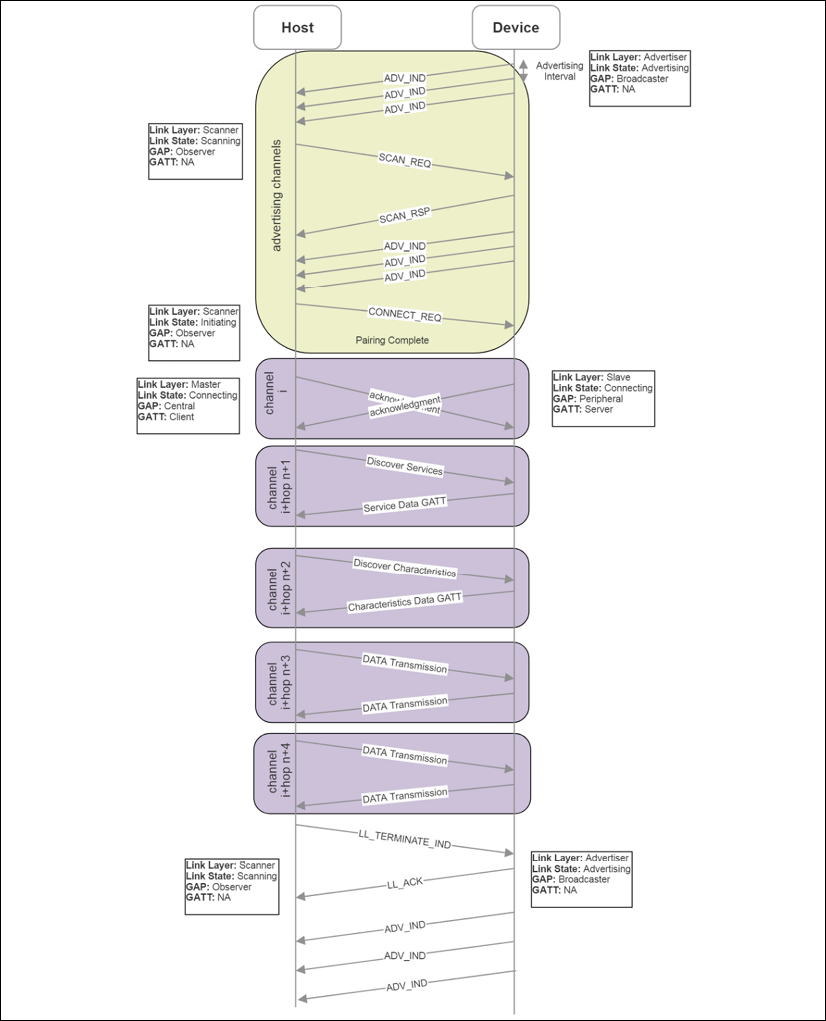
Figure 7: Phases of BLE advertising, connecting, GATT service query, and data transmission
Bluetooth profiles
Applications interface with various Bluetooth devices using profiles. Profiles define the functionality and features for each layer of the Bluetooth stack. Essentially, profiles tie the stack together and define how layers interface with each other. A profile describes the discovery characteristics that the device advertises. They are also used to describe the data formats of services and characteristics that applications use to read and write to devices. A profile doesn't exist on a device; rather, they are predefined constructs maintained and governed by the Bluetooth SIG.
The basic Bluetooth profile must contain a GAP as stated by the specification. The GAP defines the radio, baseband layer, link manager, L2CAP, and service discovery for BR/EDR devices. Likewise, for a BLE device, the GAP will define the radio, link layer, L2CAP, security manager, attribute protocol, and generic attribute profile.
The ATT attribute protocol is a client-server wire protocol optimized for low-power devices (for example, the length is never transmitted over BLE but is implied by the PDU size). ATT is also very generic, and much is left to the GATT to provide assistance. The ATT profile consists of:
- A 16-bit handle
- A UUID to define the attribute type value containing the length
The GATT logically resides on top of ATT and is used primarily, if not exclusively, for BLE devices. The GATT specifies the roles of the server and client. A GATT client is usually a peripheral device, and the GATT server is the host (for example, PC or smartphone). A GATT profile contains two components:
- Services: A service breaks up data into logical entities. There can be multiple services in a profile and each service has a unique UUID to distinguish it from others.
- Characteristics: A characteristic is the lowest level of a GATT profile and contains raw data associated with the device. Data formats are distinguished by 16-bit or 128-bit UUIDs. The designer is free to create their own characteristics that only their application can interpret.
The following image represents an example of a Bluetooth GATT profile with corresponding UUIDs for various services and characteristics.
The Bluetooth specification mandates that there can be only a single GATT server.

Figure 8: GATT profile hierarchy and example GATT used on Texas Instruments CC2650 SensorTag
The Bluetooth SIG maintains a collection of many GATT profiles. At the time of writing, there are 57 GATT profiles supported by the Bluetooth SIG: https://www.bluetooth.com/specifications/gatt. Profiles supported by the SIG include health monitors, cycling and fitness devices, environmental monitors, human interface devices, indoor positioning, object transfer, and location and navigation services, along with many others.
BR/EDR security
In some form, Bluetooth security has existed as part of the protocol since 1.0. We discuss security for BR/EDR mode and BLE separately as the mechanisms are different. Starting with BR/EDR mode, there are multiple modes of authenticating and pairing. For both BR/EDR and BLE security, it is recommended to read and follow the latest security guide provided by the US National Institute of Standards and Technology: Guide to Bluetooth Security, NIST Special Publication (SP) 800-121 Rev. 2, NIST, 5/8/2017.
Pairing requires the generation of a secret symmetric key. In BR/EDR mode, this is called the link key, while in BLE mode it's termed the long-term key. Older Bluetooth devices used a personal identification number (PIN) pairing mode to initiate link keys. Newer devices (4.1+) use SSP.
SSP provides a pairing process with a number of different association models for various use cases. SSP also uses public key cryptography to protect from eavesdropping and man-in-the-middle (MITM) attacks. The models supported by SSP include:
- Numeric comparison: For use cases where both Bluetooth devices can display a six-digit numeric value allowing a user to enter a yes/no response on each device if the numbers match.
- Passkey entry: Used in situations where one device has a numeric display and the other only has a numeric keyboard. In this case, the user enters the value seen on the first device's display on the second device's keyboard.
- Just WorksTM : For situations where one device is headless and has no keyboard or display. It only provides minimal authentication and will not thwart an MITM attack.
- Out-of-band (OOB): Used when the device has a secondary form of communication such as NFC or Wi-Fi. The secondary channel is used for discovery and cryptographic value exchange. It will only protect from eavesdropping and MITM if the OOB channel is secure.
Authentication in BR/EDR mode is a challenge-response action, for example, entering a PIN on a keypad. If the authentication fails, the device will wait for an interval before allowing a new attempt. The interval grows exponentially with each failed attempt. This is simply to frustrate the individual attempting to manually break a key code.
Encryption in BR/EDR mode can be set for the following:
- Disabled for all traffic
- Encrypted for data traffic but broadcast communication will be raw
- All communication is encrypted
The encryption uses AES-CCM cryptography.
BLE security
BLE pairing (explained earlier in this chapter) starts by a device initiating a Pairing_Request and exchanging capabilities, requirements, and so on. Nothing involving security profiles occurs at the initial phase of a pairing process. For that matter, the pairing security is similar to the four BR/EDR methods (also known as association models), but differs slightly in Bluetooth BLE 4.2:
- Numeric comparison: This is the same as Just Works, but at the end, both devices will generate a confirmation value that is displayed on the host and device screens for the user to validate the match.
- Passkey entry: Similar to BR/EDR mode, except that the non-initiating device creates a random 128-bit seed called a nonce to authenticate the connection. Every bit of the passkey is authenticated separately on each device by generating a confirmation value for that bit. The confirmation values are exchanged and should match. The process continues until all bits are processed. This provides a fairly robust solution for MITM attacks.
- Just WorksTM : After devices exchange public keys, the non-initiating device creates a nonce to generate a confirmation value Cb. It transmits the nonce and Cb to the initiating device, which in turn generates its own nonce and transmits it to the first. The initiating device will then confirm the authenticity of the non-initiating nonce by generating its own Ca value, which should match Cb. If it fails to match, the connection is corrupt. This again is different to BR/EDR mode.
- Out-of-band (OOB): This is the same as in BR/EDR mode. It will only protect from eavesdropping and MITM if the OOB channel is secure.
In BLE (as of Bluetooth 4.2), key generation uses LE secure connections. LE secure connection was developed to resolve the security hole in BLE pairing that allowed an eavesdropper to see the pairing exchange. This process uses a long-term key (LTK) to encrypt the connection. The key is based on an elliptical-curve Diffie-Hellman (ECDH) public key cryptography.
Both the master and slave will generate ECDH public-private key pairs. The two devices will exchange their public portion of their respective pairs and process the Diffie-Hellman key. At this point, the connection can be encrypted using AES-CCM cryptography.
BLE also has the ability to randomize its BD_ADDR. Remember, the BD_ADDR is a 48-bit MAC-like address. Rather than a static address for the value, as mentioned earlier in this chapter, there are three other options:
- Random static: These addresses are either burned into the device's silicon during manufacture or generated when the device power cycles. If a device routinely power cycles, a unique address will be generated and this remains secure as long as the frequency of power cycling is high. In an IoT sensor environment, that may not be the case.
- Random private resolvable: This addressing method can only be used if the Identity Resolving Key (IRK) is exchanged between the two devices during the bonding process. The device will use the IRK to encode its address into a random address in the advertisement packet. A second device that also possesses the IRK will convert the random address back into the authentic address. In this method, the device will periodically generate a new random address based off the IRK.
- Random private non-resolvable: The device address is simply a random number and a new device address can be generated at any time. This offers the highest level of security.
Beaconing
Bluetooth beaconing is a secondary effect of BLE; however, it is an important and significant technology for IoT. Because beacons are not necessarily sensors, we didn't cover them explicitly in the Chapter 3, Sensors, Endpoints, and Power Systems (although some do provide sensing information in an advertisement packet). Beaconing simply uses Bluetooth devices in LE mode to advertise on some periodic basis. Beacons never connect or pair with a host. If a beacon were to connect, all advertisements would stop, and no other device could hear that beacon. The three use cases important to retail, healthcare, asset tracking, logistics, and many other markets are:
- Static point of interest (POI)
- Broadcasting telemetry data
- Indoor positioning and geolocation services
Bluetooth advertising uses a message to contain further information in the broadcast UUID. An app on a mobile device can respond to this advertisement and perform some action if the correct advertisement is received. A typical retail use case would make use of a mobile app that would respond to the presence of a beacon advertisement in the vicinity and pop up an ad or sale information on the user's mobile device. The mobile device would communicate over Wi-Fi or cellular to retrieve additional content as well as provide critical market and shopper data to the company.
Beacons can transmit their calibrated RSSI signal strength as an advertisement. The signal strength of beacons is calibrated by manufacturers typically at a one-meter length. Indoor navigation can be performed in three different ways:
- Multiple beacons per room: This is a simple triangulation method to determine a user's location based on the advertised RSSI signal strength collected from numerous beacons in a room. Given the advertised calibrated level from each beacon and the received strength from each beacon, an algorithm could determine the approximate location of a receiver in a room. This assumes all beacons are in a fixed place.
- One beacon per room: In this scheme, one beacon is placed in each room, allowing a user to navigate between rooms and halls with the fidelity of the location being a room. This is useful in museums, airports, concert venues, and so on.
- A few beacons per building: In combination with accelerometers and gyros in a mobile device, multiple beacons in a building can allow for dead reckoning ability in a large open space. This allows a single beacon to set a starting location and the mobile device to reckon its location based on user movement.
There are two fundamental beaconing protocols used: Eddystone by Google and iBeacon by Apple. Legacy Bluetooth devices can only support a beacon message of 31 bytes. This restricts the amount of data a device can convey.
An entire iBeacon message is simply a UUID (16 bytes), a major number (two bytes), and minor number (two bytes). The UUID is specific to the application and use case. The major number further refines the use case and minor extends the use case to an even narrower case.
iBeacons provide two ways to detect devices:
- Monitoring: Monitoring works even if the associated smartphone application is not actively running.
- Ranging: Ranging works only if the application is active.
Eddystone (also known as UriBeacons) can transmit four different types of frames with varying length and frame encoding:
- Eddystone-URL: The uniform resource location. This frame allows a receiving device to display web content based on the location of the beacon. An app does not need to be installed to activate the content. The content is variable in length and applies unique compression schemes to reduce the size of the URL to a limit of 17 bytes.
- Eddystone-UID: 16-byte unique beacon ID with a 10-byte namespace and 6-byte instance. It uses Google Beacon Registry to return attachments.
- Eddystone-EID: A short-lived identifier for beacons requiring higher levels of security. With no fixed namespace and ID, the identifiers constantly rotate and require an authorized app to decode. It uses Google Beacon Registry to return attachments.
- Eddystone-TLM: Broadcasts telemetry data about the beacon itself (battery level, time since power-on, advertisement count). It broadcasts alongside URI or URL packets.
The following diagram illustrates the Bluetooth BLE advertisement packet structure for Eddystones and iBeacons. The iBeacon is simplest with a single type of frame of consistent length. Eddystone consists of four different types of frames and has variable lengths and encoding formats. Note that some fields are hardcoded, such as the length, type, and company ID for iBeacon, as well as the identifier for Eddystone.

Figure 9: Example difference between iBeacon and Eddystone advertising packets (PDU)
The scanning intervals and advertising intervals attempt to minimize the number of advertisements necessary to convey useful data within a period of time. The scanning window usually has a longer duration than the advertisement as scanners essentially have more power than a coin cell battery in a beacon. The following figure shows a process of a beacon advertising every 180ms while the host scans every 400ms.

Figure 10: An example of a host scanning with a scan interval of 400ms and a scan window of 180 ms.
The beacon advertises every 150ms on the dedicated channels 37, 38, and 39. Notice the ordering of the advertising channels isn't consecutive as frequency hopping may have adjusted the order. Some advertisements have failed to reach the host since the scan interval and advertising interval are out of phase. Only a single advertisement in the second burst reaches the host on channel 37, but by design, Bluetooth advertises on all three channels in an attempt to maximize the chance of success.
There are two fundamental challenges with architecting a beacon system. The first is the effect of advertising intervals versus the fidelity of location tracking. The second is the effect of advertising intervals versus the longevity of the battery powering the beacon. Both effects balance each other, and careful architecture is needed to deploy correctly and extend the life of the battery.
The longer the interval between beacon advertisements, the less accuracy a system will have on a moving target. For example, if a retailer is tracking the location of patrons in a store, the patrons move at walking speed of 4.5 feet/second, and a set of beacons advertises every four seconds versus another deployment that advertises every 100 ms, it will reveal different paths of motion to the retailer gathering market data. The following figure illustrates the effects of slow and fast advertising in a retail use case.

Figure 11: The effects of high-frequency advertising versus low-frequency advertising on location fidelity. The integers represent customer time spent at a particular point in the store.
A four-second advertising interval loses accuracy of the customer locations as they move about a store. Additionally, the amount of time spent at a particular point can only be tracked at discrete intervals of four seconds. The time spent at positions B and C (as the customer leaves the store) may be lost. In this case, the retailer may want to understand why the customer spent 7.8 seconds at location B and why they went back to point C on their way out.
The countereffect of frequent advertising is the impact on beacon battery life. Typically, the batteries in beacons are Li-ion CR2032 coin cells. The Hitchhikers Guide to iBeacon Hardware: A Comprehensive Report by Aislelabs. Web 14 March, 2016 (https://www.aislelabs.com/reports/beacon-guide/) has performed an analysis of battery life for some common beacons and altered their advertising interval (100 ms, 645 ms, and 900 ms). They also used different batteries with increasing stored energy. The results show that the average life ranges from 0.6 months to over one year depending on the chipset, but more importantly on the advertising interval. Along with the advertising interval, Tx power certainly affects the overall battery life, but so does the number of frames transmitted.
Setting advertising intervals too long, while beneficial for battery life and bad for location awareness, has a secondary effect. If the beacon is operating in a noisy environment and the interval is set high (>700 ms), the scanner (smartphone) will have to wait another full period to receive the advertisement packet. This can lead to apps timing out.
A fast 100 ms interval is useful to track fast-moving objects (such as asset tracking in fleet logistics or drone-based beacon harvesting). If the architect is designing to track human movement at a typical rate of 4.5 feet/second, then 250 ms to 400 ms is adequate.
A valuable exercise for the IoT architect is to understand the cost of transmission in terms of power. Essentially, the IoT device has a limited number of PDUs it can send out before the battery reaches a point where it can no longer power the device unless refreshed or energy is harvested (see Chapter 4, Communications and Information Theory). Assume an iBeacon is advertised every 500 ms and the packet length is 31 bytes (it may be longer).
Additionally, the device uses a CR2032 coin cell battery rated at 220mAh at 3.7V. The beacon electronics consume 49uA at 3V. We can now predict the life of the beacon and the efficiency of the transmission:
- Power consumption = 49uA x 3V = 0.147mW
- Bytes per second = 31 x (1 second/500 ms) x 3 channels = 186 bytes/second
- Bits per second = 186 bytes/second x 8 = 1488 bits/second
- Energy per bit = 0.147 mW / (1488 bits/second) = 0.098 uJ/bit
- Energy used for each advertisement = 0.098 uJ/bit x 31 bytes x 8 bits/byte = 24.30 uJ/advertisement
- Energy stored in battery: 220mAh x 3.7V x 3.6 seconds = 2930 J
- Life of battery = (2930 J x (1,000,000 uJ/J)) / ((24.30 uJ/advertisement) x (1 advertisement / 0.5 seconds)) x 0.7 = 42,201,646 seconds = 488 days = 1.3 years
The constant 0.7 is used for allowances in the decline of battery life, as described in Chapter 4, Communications and Information Theory. 1.3 years is a theoretical limit and most likely will not be obtained in the field due to factors such as leakage current, as well as other functionalities of the device that may need to run periodically.
As a final note on beacons with respect to Bluetooth 5, the new specification extends the length of beacon advertisements by allowing for advertisement packets to be transmitted in the data channels as well as the advertisement channels. This fundamentally breaks the 31-byte limit of an advertisement.
With Bluetooth 5, the message size can be 255 bytes. The new Bluetooth 5 advertisement channels are called secondary advertisement channels. They ensure backward compatibility with legacy Bluetooth 4 devices by defining a specific Bluetooth 5 extended type in the header. Legacy hosts will throw out the unrecognized header and simply not listen to the device.
If a Bluetooth host receives a beacon advertisement that indicates there is a secondary advertisement channel, it recognizes that more data will need to be found in the data channels. The payload of the primary advertisement packet no longer contains beacon data, but a common extended advertising payload that identifies a data channel number and a time offset. The host will then read from that particular data channel at the indicated time offset to retrieve the actual beacon data. The data could also point to another packet (which is referred to as multiple secondary advertisement chains).
This new method of transmitting very long beacon messages ensures large amounts of data could be sent to customer smartphones. Other use cases and features are now enabled as well, such as the advertisement being used to transmit synchronous data like audio streams. A beacon could send audio lectures to a smartphone as a visitor walks around a museum and looks at various art pieces.
Advertisements can also be anonymized, meaning the advertisement packet does not need to have the transmitter's address bound to it. Thus, when a device produces an anonymous advertisement, it does not transmit its own device address. This can improve privacy and reduce power consumption.
Bluetooth 5 can also transmit multiple individual advertisements (with unique data and different intervals) nearly simultaneously. This will allow Bluetooth 5 beacons to transmit Eddystone and iBeacon signals at nearly the same time without any reconfiguration.
Additionally, the Bluetooth 5 beacon can detect if it is scanned by a host. This is powerful because the beacon can detect whether a user received an advertisement and then stop transmitting to conserve power.
Bluetooth 5 range and speed enhancement
Bluetooth beacon strength is constrained and can be affected by limits placed on the transmitter power to preserve battery life. Usually, a line of sight is needed for optimal beacon range and signal strength. The following figure shows the signal strength to distance curve for typical line-of-sight Bluetooth 4.0 communication.
Bluetooth 5 extends the range only when LE Coded mode is used, as we will examine later.

Figure 12: Beacon strength is limited. Often a manufacturer limits the Tx power of a beacon to preserve battery life. As one moves from the beacon, the signal strength drops as expected. Typically a 30-foot range is a usable beacon distance (Bluetooth 4.0).
Bluetooth also has different power levels, ranges, and transmission power based on a classification for each device:
| Class number | Max output level (dBm) | Max output power (mW) | Max range | Use case |
|
1 |
20 dBm |
100 mW |
100 m |
USB adapters, access points |
|
1.2 |
10 dBm |
10 mW |
30 m (typical 5 m) |
Beacons, wearables |
|
2 |
4 dBm |
2.5 mW |
10 m |
Mobile devices, Bluetooth adapters, smart card readers |
|
3 |
0 dBm |
1 mW |
10 cm |
Bluetooth adapters |
Bluetooth 5 has improved the range as well as data rate beyond legacy Bluetooth limits. A new radio PHY is available with Bluetooth 5 called LE2M. This doubles the raw data rate of Bluetooth from 1M symbol/second to 2M symbols/second. To transfer an equal amount of data on Bluetooth 5 as opposed to Bluetooth 4, less time will be needed for transmission.
This is particularly relevant for IoT devices that operate on coin cells. The new PHY also increases the power from +10 dBm to +20 dBm, allowing for greater range.
With respect to range, Bluetooth 5 has another optional PHY for extended range transmission in BLE. This auxiliary PHY is labeled LE Coded. This PHY still uses the 1M symbol/second rate as in Bluetooth 4.0, but reduces lower packet coding of 125 Kb/s or 500 Kb/s and increases the transmission power by +20 dBm. This has the effect of increasing the range by 4x over Bluetooth 4.0 and having better penetration within buildings. The LE Coded PHY does increase power consumption for the benefit of increased range.
Bluetooth mesh
Bluetooth also provides the adjunct specification for mesh networking using the BLE stacks. This section covers the Bluetooth mesh architecture in detail.
Bluetooth mesh
Before the Bluetooth SIG's official mesh specification with Bluetooth 5, there were proprietary and ad hoc schemes using older Bluetooth versions to build mesh fabrics. After the Bluetooth 5 specification was released, however, the SIG focused on formalizing mesh networking in Bluetooth. The Bluetooth SIG published the mesh profile, device, and model specification 1.0 on July 13, 2017. This came six months after the Bluetooth 5.0 specification was released. The three specifications published by the Bluetooth SIG are as follows:
- Mesh profile specification 1.0: Defines the fundamental requirements to enable an interoperable mesh networking solution
- Mesh model specification 1.0: Basic functionality of nodes on the mesh network
- Mesh device properties 1.0: Defines the device properties required for the mesh model specification
It is not yet known whether there is any limit to the size of the mesh network. There are some limits built into the specification. As of the 1.0 specification, there can be up to 32,767 nodes in a Bluetooth mesh and 16,384 physical groups. The maximum time-to-live(TTL), which is indicative of the depth of the mesh, is 127.
Bluetooth 5 mesh theoretically allows for 2128 virtual groups. Practically, grouping will be much more constrained.
Bluetooth mesh is based on BLE and sits on the BLE physical and link layer described earlier. On top of that layer is a stack of mesh-specific layers:
- Models: Implements behaviors, states, and bindings on one or more model specifications.
- Foundation models: Configuration and management of the mesh network.
- Access layer: Defines the format of application data, encryption process, and data verification.
- Upper transport layer: Manages the authentication, encryption, and decryption of data passing to and from the access layer. Transports control messages such as friendships and heartbeats.
- Lower transport layer: Performs segmentation and reassembly (SAR) of fragmented PDUs if necessary.
- Network layer: Determines which network interface to output messages on. It manages the various address types and supports many bearers.
- Bearer layer: Defines how mesh PDUs are handled. Two types of PDUs are supported: advertising bearer and GATT bearer. The advertising bearer handles the transmission and reception of mesh PDUs, while the GATT bearer provides a proxy for devices that don't support the advertising bearer.
- BLE: The complete BLE specification.
Bluetooth mesh can incorporate mesh networking or BLE functions. A device that is capable of mesh and BLE support can communicate to other devices like smartphones or have beacon functions. Shown in the following figure is the Bluetooth mesh stack. What is important to realize is the replacement of the stack above the link layer.

Figure 13: Bluetooth mesh specification 1.0 stack
Bluetooth mesh topology
Bluetooth mesh uses the concept of a flood network. In a flood network, each incoming packet received by a node in the mesh is sent through every outgoing link, except the link to the parent of the message. Flooding has the advantage that if a packet can be delivered, it will be delivered (albeit probably many times via many routes). It will automatically find the shortest route (which can vary by signal quality and distance in a dynamic mesh). The algorithm is the simplest to implement as far as routing protocols are concerned.
Additionally, it requires no central manager such as a Wi-Fi network based around a central router. For comparison, the alternate types of mesh routing include tree-based algorithms. With tree algorithms (or cluster-tree algorithms), a coordinator is necessary to instantiate the network and becomes the parent node. Trees aren't necessarily true mesh networks, however. Other mesh routing protocols include proactive routing, which keeps up-to-date routing tables on each node, and reactive routing, which only updates routing tables on each node on demand; for example, when data needs to be sent through a node. Zigbee (covered later) is a form of proactive routing called an Ad Hoc On-Demand Distance Vector (AODV). The following figure illustrates a flood broadcast. The time of arrival at each level can vary dynamically from node to node. Additionally, the mesh network must be resilient to duplicate messages arriving at any node as in the case of node 7 and node D.

Figure 14: Flood mesh architecture (S = Source, D = Destination): Source produces data that propagates and flows through every node in the mesh
The main disadvantage with a flood network is bandwidth waste. Depending on the fan out from each node, the congestion on a Bluetooth mesh can be significant. Another issue is a denial-of-service attack. If the mesh simply fans out messages, a facility is needed to know when to stop transmissions. Bluetooth accomplishes this through time-to-live identifiers, which we will cover later in this chapter.
The entities that comprise Bluetooth mesh include the following:
- Nodes: Bluetooth devices that have been previously provisioned and are members of a mesh.
- Unprovisioned devices: Devices with the potential to join a mesh fabric that is not yet part of a mesh and has not been provisioned.
- Elements: If a node contains multiple constituent devices, those sub-devices are called elements. Each part can be independently controlled and addressed. An example could be a Bluetooth node with temperature, humidity, and lumens sensors. This would be a single node (sensor) with three elements.
- Mesh gateway: A node that can translate messages between the mesh and a non-Bluetooth technology.
Once provisioned, a node may support an optional set of features, which include:
- Relay: A node that supports relay is termed a relay node and can retransmit messages received.
- Proxy: This allows BLE devices that do not support Bluetooth mesh natively to interact with nodes on the mesh. It is performed using a proxy node. The proxy exposes a GATT interface with the legacy Bluetooth device, and a proxy protocol based on a connection-oriented bearer is defined. The legacy device reads and writes to the GATT proxy protocol, and the proxy node transforms the messages into true mesh PDUs.
- Low power: Some nodes on the mesh need to obtain extremely low levels of power consumption. They may serve up environmental sensor information (such as temperature) once an hour and be configured by a host or cloud managed tool once a year. That type of device cannot be placed in a listening mode when a message will only arrive once a year. The node enters a role termed the low power node (LPN), which pairs it with a friend node. The LPN enters a deep sleep state and polls the associated friend for any messages that may have arrived while it was sleeping.
- Friend: A friend node is associated with the LPN but is not necessarily power constrained like an LPN. A friend may use a dedicated circuit or wall power. The friend's duty is to store and buffer messages destined for the LPN until the LPN wakes and polls it for messages. Many messages may be stored, and the friend will transmit them in order using a more data (MD) flag.
The following diagram illustrates a Bluetooth mesh topology with the various components as they would be associated with one another in a real mesh.

Figure 15: Bluetooth mesh topology. Note the classes including nodes, LPNs, friends, gateways, relay nodes, and unprovisioned nodes.
A Bluetooth mesh will cache messages on each node; this is crucial in a flood network. As the same message may arrive at different times from different sources, the cache provides a lookup of recent messages received and processed. If the new message is identical to one in the cache, it is discarded. This ensures system idempotence.
Each message carries a TTL field. If a message is received by a node and then retransmitted, the TTL is decremented by one. This is a safety mechanism to prevent endless loops of traversing messages in a mesh. It also prevents networks from creating amplifying denial-of-service attacks.
A heartbeat message is broadcast periodically from each node to the mesh. The heartbeat informs the fabric that the node is still present and healthy. It also allows the mesh to know how far away the node is and if it has changed distance since the last heartbeat. Essentially, it is counting the number of hops to reach the node. This process allows the mesh to reorganize and self-heal.
Bluetooth mesh addressing modes
Bluetooth mesh uses three forms of addressing:
- Unicast addressing: This uniquely identifies a single element in the mesh. The address is assigned during the provisioning process.
- Group addressing: This is a form of multicast addressing that can represent one or more elements. These are either predefined by the Bluetooth SID as SIG fixed group addresses or assigned on the fly.
- Virtual addressing: An address can be assigned to more than one node and more than one element. Virtual addressing uses a 128-bit UUID. The intent is the UUID can be preset by a manufacturer to allow them to address their product globally.
The Bluetooth mesh protocol starts with 384-byte long messages that are segmented into 11-byte parcels. All communication in a Bluetooth mesh is message-orientated. There are two forms of messages that can be transmitted:
- Acknowledged messages: These require a response from node(s) that receive the message. The acknowledgment also includes data that the originator requested in the original message. Therefore, this acknowledged message serves dual purposes.
- Unacknowledged messages: These do not require a response from the receiver.
To send a message from a node is also known as publishing. When nodes are configured to process select messages sent to particular addresses, it is termed subscribing. Each message is encrypted and authenticated using a network key and an application key.
The application key is particular to an app or use case (for example, turning a light on versus configuring the color of an LED light). Nodes will publish events (light switches), and other nodes will subscribe to those events (lamps and lightbulbs). The following figure illustrates a Bluetooth mesh topology. Here, nodes can subscribe to multiple events (lobby lights and hallway lights). The circles represent group addresses. A switch would publish to a group.

Figure 16: Bluetooth mesh publish-subscribe model
Bluetooth mesh introduces the concept of group messaging. In a mesh, you may have a grouping of similar objects such as bath lights or lobby lights. This aids in usability; for example, if a new light is added, only that light needs to be provisioned, and the rest of the mesh doesn't need any change.
The light switches in the preceding example have two states: on and off. Bluetooth mesh defines states, and in this case, they are labeled generic On-Off. Generic states and messages support many types of devices from lights to fans to actuators. They are a quick way to reuse a model for a general (or generic) purpose. As the system moves from one state to another, this is termed a state transition on the mesh. States can also be bound to each other. If a state changes, it can affect the transition to another state. As an example, a mesh controlling a ceiling fan may have a speed control state that, when it gets to a value of zero, changes the generic On-Off state to off.
Properties are similar to states but have more than binary values. For example, a temperature sensor may have a state Temperature 8 to signify and publish an eight-bit temperature value. A property can either be set as manufacturer (read-only) by the supplier of the element or as admin, which allows read-write access. Both states and properties are communicated through messages on the mesh. Messages come in three types:
- Get: Requests a value of a given state from one or more nodes
- Set: Changes a value of a state
- Status: Is a response to a
getthat contains the data
All of these concepts of states and properties ultimately form a model (the highest level of the Bluetooth mesh stack). A model can be a server, in which case it defines states and state transitions. Alternatively, a model can be a client that doesn't define any states; rather, it defines state interaction messages to use with get, set, and status. A control model can support a hybrid of server and client models.
Mesh networking can also make use of Bluetooth 5 standard features such as anonymous advertisements and multiple advertisement sets. Take the case of a mesh that connects to a phone for voice communication, yet simultaneously is relaying packets for other uses. By using multiple advertisement sets, both use cases can be managed simultaneously.
Bluetooth mesh provisioning
A node may join a mesh by the act of provisioning. Provisioning is a secure process that takes an unprovisioned and insecure device and transforms it into a node in the mesh. The node will first secure a NetKey from the mesh.
At least one NetKey must be on each device in the mesh to join. Devices are added to the mesh through a provisioner. The provisioner distributes the network key and a unique address to an unprovisioned device. The provisioning process uses ECDH key exchange to create a temporary key to encrypt the network key. This provides security from an MITM attack during provisioning. The device key derived from the elliptical curve is used to encrypt messages sent from the provisioner to the device.
The provisioning process is as follows:
- An unprovisioned device broadcasts a mesh beacon advertising packet.
- The provisioner sends an invitation to the device. The unprovisioned device responds with a provisioning capabilities PDU.
- The provisioner and device exchange public keys.
- The unprovisioned device outputs a random number to the user. The user enters the digits (or identity) into the provisioner, and a cryptographic exchange starts to complete the authentication phase.
- A session key is derived by each of the two devices from the private key and the exchanged public keys. The session key is used to secure the data needed to complete the provisioning process, including securing the NetKey.
- The device changes state from an unprovisioned device to a node and is now in possession of the NetKey, a unicast address, and a mesh security parameter called the IV index.
Bluetooth 5.1 technology
In January of 2019, the Bluetooth SIG presented the first update to the 5.0 specification: Bluetooth 5.1. Major enhancements included specific features for location tracking, advertising, and faster provisioning. Specific new features in the specification include:
- Three-dimensional direction finding
- GATT caching enhancements
- Randomizing advertising channel indices
- Periodic advertising sync transfers
- A myriad of feature enhancements
Bluetooth 5.1 direction finding
A significant new ability in Bluetooth 5.1 is the ability to locate objects with a high degree of precision. This technology would be used where GPS is unavailable or impractical. For example, a museum could use directional beacons within large exhibit halls to guide patrons and also point them to or have them face exhibits of interest. These uses cases fall under real-time locating systems (RTLSes) and indoor positioning systems (IPSes). In previous Bluetooth designs (as well as other wireless protocols), proximity and positioning solutions were derived simply based on an object's RSSI signal strength. The further a receiver was from a transmitter, the lower the RSSI level. From this a derived form of distance could be generated. However, this had a high degree of inaccuracy and was subject to environmental conditions such as signal changes penetrating various barriers.
Whereas previous Bluetooth versions provided roughly meter-level proximity tracking, Bluetooth 5.1 allows for near centimeter-level accuracy and tracking. In Bluetooth 5.1, two different methods can be used to derive distance and angle with a very high degree of accuracy. The two methods are:
- Angle of arrival (AoA): A device (for example, a smart tag) transmits a specific direction-finding packet via a single antenna while a receiving device will collect the signal through an antenna array. This is primarily useful for RTLSes.
- Angle of departure (AoD): A device (for example, beacon or IPS) uses its antenna array to transmit a specific packet to a receiving device (smartphone) where the signal is processed to determine the transmission coordinates. This is primarily useful for indoor wayfinding.

Figure 17: Bluetooth 5.1 positioning modes of operation: AoA and AoD
In AoA cases, a receiver will utilize a linear array of antennas. If the transmitter broadcasts a signal in the same normal plane as the linear array, each antenna in the receiving system will see the same signal in the same phase. However, if the transmission angle is offset by some degree, the receiving antenna will each see the signal in a different phase. This is how the incident angle can be derived.
The antenna for this Bluetooth application would be a uniform linear array (ULA) or a uniform rectangular array (URA). The difference is that the linear array is a single straight line of antennas along a plane, whereas the rectangular array is a two-dimensional grid. The ULA can only measure a single incident angle (azimuth), while the URA can measure both the elevation and azimuth angles of a signal. URA systems can also be constructed to track and entire three-dimensional space by using an additional array to complete the x, y, and z axes. In general, the maximum distance between two antennas is half a wavelength. In Bluetooth, the carrier frequency is 2.4 GHz, while the speed of light is 300,000 km/s. This implies the wavelength is 0.125 m and that the maximum antenna separation is 0.0625 m.
Note: There are considerable challenges in constructing a multidimensional antenna array. Antennas in close proximity to each other will attempt to affect each other through a process called mutual coupling. This is an electromagnetic effect in that a close antenna will absorb the energy from neighbors. This in turn decreases the amount of energy transmitted to the intended receiver and causes inefficiencies as well as scan blindness. Scan blindness creates nearly complete blind spots at certain angles from the transmitting array. Care must be taken to qualify the antenna source.
In Bluetooth direction tracking, each antenna in the array is sampled in series. The order they are sampled is finely tuned the design of the antenna array. The IQ data captured is then passed up the traditional BLE stack through the HCI. Bluetooth 5.1 has changed the link layer and HCI to support a new field called the constant tone extension (CTE). CTE is a stream of logical "1" presented on the carrier signal. This presents itself as a logical 250 kHz wave upon the Bluetooth carrier signal. Since the CTE exists at the end of normal packets, it can be used simultaneously with normal advertising and BLE messages. The following graphic illustrates how and where CTE information is embedded within the existing Bluetooth advertising packet.
The CTE message can only be used for Bluetooth systems not using an encoded PHY. Thus, long range modes of Bluetooth 5 are not supported for position tracking.

Figure 18: CTE packet structure. Note the CP bit within the header field must be enabled to use CTE structures. Details of the CTE reside in the CTE Info.
The theory of operation is as follows. The phase difference between the two antennas is proportional to the difference between their respective distances from a transmitter. The path lengths are dependent on the direction of travel of the incoming signal. The measurement starts by sending the CTE constant tone signal (with no modulation or phase shifting). This allows enough time for the receiver to synchronize with the transmitter. The receiver samples retrieved from the array are called IQ-samples for "In-phase" and "Quadrature-phase." This pair is considered a complex value of phase and amplitude. It then stores the IQ samples and processes them in the HCI.

Figure 19: The received signal for two antennas will differ by a phase difference (![]() ). This difference is proportional to the respective distances for each receiving antenna to the transmitting source.
). This difference is proportional to the respective distances for each receiving antenna to the transmitting source.
Another way to think about the phase difference is using polar coordinates as shown in the following figure. Because we are measuring the phase 2 signals or more signals (most likely many signals in modern antenna arrays), we must turn off all forms of phase shifting modulation for Bluetooth.

Figure 20: The received signal for two antennas will differ by a phase difference (![]() ). Here d is the distance between antennas. The incoming angle that must be derived is
). Here d is the distance between antennas. The incoming angle that must be derived is ![]() . This difference is proportional to the respective distances for the receiving antennas to the transmitting source.
. This difference is proportional to the respective distances for the receiving antennas to the transmitting source.
The positioning algorithm is executed within the HCI to determine phase angle. Bluetooth 5.1 does not define a specific angle estimation algorithm to use. The most basic algorithm to determine the angle of arrival, ![]() , based on the difference of phase
, based on the difference of phase ![]() is through simple trigonometry. Since we know the distances of antennas in our array, we can derive the AoA by first calculating the phase difference:
is through simple trigonometry. Since we know the distances of antennas in our array, we can derive the AoA by first calculating the phase difference:

And then resolving the angle:

While this method works, it has fundamental limitations. First, it works for only a single incoming signal. Bluetooth can make use of multipath scenarios, and this simple angle formula wouldn't compensate well. Additionally, this algorithm can be easily subject to noise.
Other more advanced proximity and angle estimation algorithms to consider in the HCI layer are:
| Technique | Theory of Operation | Quality |
|
Classical beamforming |
Beamforming algorithms use multiple antennas and adjust their respective signal weights through a steering vector a.
Here x is the collection of IQ samples, s is the signal, and n is the noise. |
Poor accuracy. |
|
Bartlett beamforming |
Magnifies signals from certain directions by adjusting phase shift. |
Low resolution when resolving multiple sources. |
|
Minimum variance distortionless response |
Attempts to maintain the target signal direction while minimizing signals from other directions. |
Resolves better than the Bartlett method. |
|
Spatial smoothing |
Resolves multipath issues and can be used in conjunction with subspace algorithms like MUSIC. |
Has a tendency to reduce the covariance matrix and therefore reduce the accuracy. |
|
Multiple signal classification (MUSIC) |
Subspace estimator that uses eigen decomposition on a covariance matrix. The algorithm will loop through all |
Computationally the most complex but produces significant accuracy in direction tracking. It also requires a number of parameters to be known in advance. This can be problematic indoors or where multipath effects are prevalent. |
|
Estimation of signal parameters via rotational invariant techniques (ESPRIT) |
Adjusts the steering vector based on the fact that one element is in constant phase shift from an earlier element. |
Even great computational load than MUSIC. |
ESPRIT and MUSIC are called subspace algorithms because they attempt to decompose the received signals into a "signal space" and a "noise space." Subspace algorithms are generally more accurate than beamforming algorithms but are also computationally heavy.
These advanced angle resolution algorithms are extremely computationally expensive in terms of CPU resources and memory. From an IoT perspective, you should not expect that these algorithms would run on far edge devices and sensors, especially power-constrained battery-based devices. Rather, substantial edge computing devices with sufficient floating-point processing would be necessary to run these algorithms.
Bluetooth 5.1 GATT caching
A new feature in Bluetooth 5.1 is GATT caching, which attempts to better optimize the BLE service attachment performance. We learned that the GATT is queried during the service discovery phase of BLE provisioning. Many devices will never change their GATT profile, which typically consists of services, characteristics and descriptors. For example, a client Bluetooth thermal sensor probably will never change its characteristics, describing the type of values that can be queried on the device.
Bluetooth 4.0 introduced the Service Change Indication feature. This feature allows clients that had cached GATT information of a device to set a characteristic flag (Service Changed) to force a server to report any changes in its GATT structure. This has several issues:
- Each server would need to maintain storage information of every server it connected to and whether it had informed that server via the Service Change Indication that its GATT characteristics have changed. This placed storage burdens on small embedded IoT devices.
- The Service Change feature only worked with devices that have already bonded. This rule in the previous specification caused unnecessary energy consumption and user experience issues for various devices.
- There could be a race condition. For example, after connecting to a server, a client could time-out waiting for a Service Change notification. The client would then proceed to send regular ATT PDUs as normal but later receive a Service Change Indication from the server.
GATT caching in Bluetooth 5.1 allows clients to skip the service discovery phase when nothing has changed in the GATT. This improves the speed and energy consumption as well as eliminate potential race conditions. Untrusted devices that have not previously bonded may now cache attribute tables across connections.
To use this feature, two Generic Attribute Service members are used: Database Hash and Client Support Features. The Database Hash is a standard 128-bit AES-CMAC hash constructed from the server's attribute table. Upon establishing a connection, a client must immediately read and cache the hash value. If the server ever changes its characteristics (therefore generating a new hash), the client will recognize the difference. The client in this case most likely has more resources and storage than small IoT endpoints to store many hash values for a variety of trusted and untrusted devices. The client has the ability to recognize that it has previously connected to the device and the attributes are unchanged; therefore, it can skip service discovery. This offers a significant improvement in energy consumption and time to establish connections than previous architectures.
The Client Support Features allow for a technique called Robust Caching. The system can now be in one of two states: change-aware and change-unaware. If Robust Caching is enabled, then the server that has visibility to these states can send a "database out-of-sync error" in response to any GATT operation. This informs the client that the database is out of date. The client will ignore all ATT commands received while the client believes the server is in a change-unaware state. If the client performs a service discovery and updates its tables and Database Hash, it can then send a Service Changed Indication, and the client will transition to a change-aware state. This is similar to the older Service Change Indication but eliminates the possibility of a race condition.
Bluetooth 5.1 randomized advertising channel indexing
BLE utilizes channels 37 (2402 MHz), 38 (2426 MHz), and 39 (2480 MHz) for advertising messages. In Bluetooth 5.0 and previous protocols, advertising messages rotate through these channels in a strict order when all the channels are in use. This often will lead to packet collisions when two or more devices are in the same proximity. As more devices enter the Bluetooth field, more collisions will occur. This will waste energy and degrade performance. To remedy this, Bluetooth 5.1 allows for advertising indices to be selected at random but follows a pattern of six potential orders:
- Channel 37 --> Channel 38 --> Channel 39
- Channel 37 --> Channel 39 --> Channel 38
- Channel 38 --> Channel 37 --> Channel 39
- Channel 38 --> Channel 39 --> Channel 37
- Channel 39 --> Channel 37 --> Channel 38
- Channel 39 --> Channel 38 --> Channel 37
The following figures show the difference between previous Bluetooth strict order advertising and Bluetooth 5.1 randomized advertising processes:

Figure 21: Legacy advertising process. Note the strict channel ordering 37 à 38 à 39. In a congested Bluetooth PAN, this has the potential to cause collisions.

Figure 22: Bluetooth 5.1 randomized advertising channel indexing
Bluetooth 5.1 periodic advertising sync transfer
As mentioned in the last section, all advertising messages transpire on channels 37, 38, and 39. Advertising event windows are separated from each other by a pseudorandom (advDelay) value of 0 ms to 10 ms. This assists with collision avoidance, but it is restrictive for a variety of applications. However, this complicates the roles of the scanning system that must by synchronized with advertisements being broadcast.

Figure 23: Legacy Bluetooth advertising: The advertising interval (advInterval) is always an integer multiple of 0.625 ms and will range from 20 ms to 10,485.759375 s. The delay between advertising events (advDelay) is a pseudo-random value ranging from 0 ms to 10 ms. The random gap between successive advertising events assists in collision avoidance but complicates the role of the scanner, which must attempt to synchronize with the random timing of packets being delivered.
With periodic advertising, a device can specify a predefined interval that the scanning host can synchronize to. This is accomplished using extended advertising packets. This method of synchronized advertising can have substantial power savings benefits for energy constrained devices by allowing the advertiser (as well as the scanner) to sleep and wake up at set intervals to send and receive advertising messages.

Figure 24: Enabling periodic advertising starts by using primary advertising channels and transmitting ADV_EXT_IND messages. This informs the scanner which PHY and secondary channel will be used for communication. The advertising device will then send information such as the channel map and the desired interval of messages. This predefined interval will then be fixed and used by the scanner to synchronize with the advertiser.
Periodic advertising has a beneficial role in many use cases, but some power constrained devices may not have the resources capable of supporting frequent advertising. A feature called periodic advertising sync transfer (PAST) allows another proxy device that is not power- or resource-constrained to perform all the synchronization work and then pass the synchronization details to the constrained devices. A typical use case may be a smartphone that acts as a proxy for a paired smartwatch. If the phone (scanner) receives advertisements from a beacon, it can transmit data received from periodic AUX_SYNC_IND packets to the smartwatch. Since the watch most likely is more energy-constrained than the smartphone, the watch will only receive select advertising information.
A new link layer control message called LL_PERIODIC_SYNC_IND has been created in Bluetooth 5.1 to allow for the smartphone to transfer advertising messages to the smartwatch without the need of the watch to be constantly scanning for advertising messages. Without PAST, the smartwatch would consume extra energy to receive periodic advertisements.

Figure 25: An example of using PAST. In this case, an energy-constrained device (smartwatch or wearable) has paired to a smartphone. Both receive periodic advertisements from an IoT temperature sensor and this is suboptimal in terms of system energy efficiency. The system on the right makes use of the LL_PERIODIC_SYNC_ADV allowing the wearable to request advertising synchronization from the smartphone. The smartphone in this case is a proxy for advertising messages that the wearable may want to use.
Bluetooth 5.1 minor enhancements
A number of additional issues and small features were added to the Bluetooth 5.1 design:
- HCI support for debug keys in LE secure connections. When Bluetooth is using a secure Diffie-Hellman key protocol to establish secure communication, it is impossible to obtain the shared key and use it for the purpose of debugging, qualification, or development work.
This change allows LE secure connections to work with Diffie-Hellman protocols by adding an HCI command to inform the host to use debug key values.
- Sleep clock accuracy update mechanism. Normally when connections are established, a master device informs a slave of the accuracy of its internal clock using the sleep clock accuracy (SCA) field. If the master is connected to several devices, it may be required to change its clock accuracy. Previously a host had no way to inform the attached devices that the clock accuracy had changed. A new link layer message called
LL_CLOCK_ACCURACY_REQcan be transmitted to connected devices to allow them to adjust the clock in sync with the master. This can lower system power. - Use of the AdvDataInfo (ADI) field in scan response data. This is a legacy defect exposed in extended advertising of Bluetooth 5.0. This field was not used in scan responses in Bluetooth 5.0 but is corrected in 5.1.
- Interaction between QoS and flow specification. This is a legacy BR/EDR enhancement and clarification of rules.
- Host channel classification for secondary advertising. Secondary advertising channels can now be classified as "bad" through the HCI command
LE_Set_Host_Channel_Classification. - Allowance for advertising Set IDs (SIDs) to appear in scan response reports. These are used in extended advertising fields of Bluetooth 5.0 but never appeared in scan responses.
IEEE 802.15.4
The IEEE 802.15.4 is a standard WPAN defined by the IEEE 802.15 working group. The model was ratified in 2003 and forms the basis of many other protocols including Thread (covered later), Zigbee (covered later in this chapter), WirelessHART, and others.
802.15.4 only defines the bottom portion (PHY and data link layer) of the stack and not the upper layers. It is up to other consortiums and working groups to build a full network solution. The goal of 802.15.4 and the protocols that sit on it is a low-cost WPAN with low power consumption. The latest specification is the IEEE 802.15.4e specification ratified on February 6, 2012, which is the version we will discuss in this chapter.
IEEE 802.15.4 architecture
The IEEE 802.15.4 protocol operates in the unlicensed spectrum in three different radio frequency bands: 868 MHz, 915 MHz, and 2400 MHz. The intent is to have as wide a geographical footprint as possible, which implies three different bands and multiple modulation techniques. While the lower frequencies allow 802.15 to have fewer issues with RF interference or range, the 2.4 GHz band is by far the most often used 802.15.4 band worldwide. The higher frequency band has gained its popularity because the higher speed allows for shorter duty cycles on transmitting and receiving, thus conserving power.
The other factor that has made the 2.4 GHz band popular is its acceptance in the market due to the popularity of Bluetooth. The following table lists various modulation techniques, geographical areas, and data rates for various 802.15.4 bands.
| Frequency range (MHz) | Channel numbers | Modulation | Data rate (Kbps) | Region |
|
868.3 |
1 channel: 0 |
BPSK O-QPSK ASK |
20 100 250 |
Europe |
|
902-928 |
10 channels: 1-10 |
BPSK O-QPSK ASK |
40 250 250 |
North America, Australia |
|
2405-2480 |
16 channels: 11-26 |
O-QPSK |
250 |
Worldwide |
The typical range of an 802.15.4-based protocol is roughly 200 meters in an open-air, line-of-sight test. Indoors, the typical range is roughly 30 m. Higher power transceivers (15 dBm) or mesh networking can be used to extend the range. The following graphic shows the three bands used by 802.15.4 and the frequency distribution.

Figure 26: IEEE 802.15.4 bands and frequency allocations: the 915 MHz band uses a 2 MHz frequency separation and the 2.4GHz band uses a 5 MHz frequency separation
To manage a shared frequency space, 802.15.4 and most other wireless protocols use some form of carrier sense multiple access with collision avoidance (CSMA/CA). Since it is impossible to listen to a channel while transmitting on the same channel, collision detection schemes don't work; therefore, we use collision avoidance. CSMA/CA simply listens to a specific channel for a predetermined amount of time. If the channel is sensed to be "idle," then it transmits by first sending a signal telling all other transmitters the channel is busy. If the channel is busy, then the transmission is deferred for a random period of time. In a closed environment, CSMA/CA will provide 36 percent channel usage; however, in real-world scenarios, only 18 percent of the channels will be usable.
The IEEE 802.15.4 group defines the operational transmit power to be capable of at least 3 dBm and the receiver sensitivity to be -85 dBm at 2.4 GHz and -91 dBm at 868/915 MHz. Typically, this implies a 15 mA to 30 mA current for transmission and a 18 mA to 37 mA current for the reception.
The data rate as state peaks at 250 kbps using the offset quadrature phase shift key.
The protocol stack only consists of the bottom two layers of the OSI model (PHY and MAC). The PHY is responsible for symbol encoding, bit modulation, bit demodulation, and packet synchronization. It also performs transmit-receiving mode switching and intra-packet timing/acknowledgment delay control. Shown in the following figure is the 802.15.4 protocol stack as a comparison to the OSI model.

Figure 27: IEEE 802.15.4 protocol stack: Only PHY and MAC layers are defined; other standards and organizations are free to incorporate layers 3 to 7 above the PHY and MAC
On top of the physical layer is the data link layer responsible for detecting and correcting errors on the physical link. This layer also controls the media access control (MAC) layer to handle collision avoidance using protocols such as CSMA/CA. The MAC layer is typically implemented in software and runs on a microcontroller (MCU) such as the popular ARM Cortex M3 or even an 8-bit ATmega core. There are a few silicon vendors that have incorporated the MAC in pure silicon, such as Microchip Technology Inc.
The interface from the MAC to the upper layers of the stack are provided through two interfaces called the Service Access Points (SAPs):
- MAC-SAP: For data management
- MLME-SAP: For control and monitoring (MAC layer management entity)
There are two types of communication in IEEE 802.15.4: beacon and beaconless communication.
For a beacon-based network, the MAC layer can generate beacons that allow a device to enter a PAN as well as provide timing events for a device to enter a channel to communicate. The beacon is also used for battery-based devices that are normally sleeping. The device wakes on a periodic timer and listens for a beacon from its neighbors. If a beacon is heard, it begins a phase called a SuperFrame interval where time slots are pre-allocated to guarantee bandwidth to devices, and devices can call for a neighbor node attention. The SuperFrame interval (SO) and beacon interval (BO) are fully controllable by the PAN coordinator. The SuperFrame is divided into 16 equally sized time slots with one dedicated as the beacon of that SuperFrame. Slotted CSMA/CA channel access is used in beacon-based networks.
The guaranteed time slots (GTSes) can be assigned to specific devices preventing any form of contention. Up to seven GTS domains are allowed. The GTS slots are allocated by the PAN coordinator and announced in the beacon it broadcasts. The PAN coordinator can change the GTS allocations on the fly dynamically based on system load, requirements, and capacity. The GTS direction (transmit or receive) is predetermined before the GTS starts. A device may request one transmit and/or one receive GTS.
The SuperFrame has contention access periods (CAPs) where there is crosstalk on the channel and contention free periods (CFPs) where the frame can be used for transmission and GTSes. The following figure illustrates a SuperFrame consisting of 16 equal time slots bounded by beacon signals (one of which must be a beacon). A contention free period will be further divided into GTSes, and one or more windows (GTSWs) may be allocated to a particular device. No other device may use that channel during a GTS.

Figure 28: IEEE 802.15.4 SuperFrame sequence
In addition to beacon-based networking, IEEE 802.15.4 allows for beacon-less networking. This is a much simpler scheme where no beacon frame is transmitted by the PAN coordinator. It implies, however, that all nodes are in a receiving mode all the time. This provides full-time contention access through the use of unslotted CSMA/CA. A transmitting node will perform a clear channel assessment (CCA) in which it listens to the channel to detect if it's used and then transmit if clear. CCA is part of a CSMA/CA algorithm and is used to "sense" whether a channel is used. A device can receive access to a channel if it is clear of other traffic from other devices (including non-802.15.4 devices). In the event a channel is busy, the algorithm enters a "back-off" algorithm and waits a random amount of time to retry the CCA. The IEEE 802.15.4 group specifies the following for CCA usage:
- CCA mode 1: Energy above threshold (lowest). The CCA will report a busy medium on detecting any energy greater than a threshold value (ED).
- CCA mode 2: Carrier sense only (medium – default). This mode causes CCA to report a busy medium only if a direct-sequence spread spectrum (DSSS) signal is detected. The signal may be above or below the ED threshold.
- CCA mode 3: Carrier sense with energy above threshold (strongest). In this mode, the CCA reports busy if it detects a DSSS signal with an energy above the ED threshold.
- CCA mode 4: A carrier sense detection mode with a timer. The CCA starts a timer of some number of milliseconds and will report busy only if it detects a high-rate PHY signal. CCA will report the medium is idle if the timer expires and no high-rate signal is observed.
- CCA Mode 5: A combination of carrier sense and energy above a threshold mode.
Note regarding CCA modes:
- Energy detection will be at most 10 dB above specified receiver sensitivity. CCA detection time will equal eight symbol periods.
- It should be noted that CCA modes that are based on energy detection consume the least amount of energy for the device.
This mode will consume much more power than beacon-based communication.
IEEE 802.15.4 topology
There are two fundamental device types in IEEE 802.15.4:
- Full function device (FFD): Supports any network topology, can be a network (PAN) coordinator, and can communicate to any device PAN coordinator
- Reduced function device (RFD): Limited to only a star topology, cannot perform as a network coordinator, and can only communicate with a network coordinator
The star topology is the simplest but requires all messages between peer nodes to travel through the PAN coordinator for routing. A peer-to-peer topology is a typical mesh and can communicate directly with neighbor nodes. Building more complicated networks and topologies is the duty of the higher-level protocols, which we will discuss in the Zigbee section.
The PAN coordinator has a unique role that is to set up and manage the PAN. It also has the duty of transmitting network beacons and storing node information. Unlike sensors that may use battery or energy harvesting power sources, the PAN coordinator is constantly receiving transmissions and is usually on a dedicated power line (wall power). The PAN coordinator is always an FFD.
The RFD or even low-power FFDs can by-battery based. Their role is to search for available networks and transfer data as necessary. These devices can be put into a sleep state for very long periods of time. The following figure is a diagram of a star versus peer-to-peer topology.

Figure 29: IEEE 802.15.4 guidance on network topologies. Implementer of 802.15.4 is free to build other network topologies.
Within the PAN, broadcast messages are allowed. To broadcast to the entire fabric, one only needs to specify the PAN ID of 0xFFFF.
IEEE 802.15.4 address modes and packet structure
The standard dictates that all addresses are based on unique 64-bit values (IEEE address or MAC address). However, to conserve bandwidth and reduce the energy of transmitting such large addresses, 802.15.4 allows a device joining a network to "trade in" its unique 64-bit address for a short 16-bit local address, allowing for more efficient transmission and lower energy.
This trade-in process is the responsibility of the PAN coordinator. We call this 16-bit local address the PAN ID. The whole PAN network itself has a PAN identifier, as multiple PANs can exist. The following figure is a diagram of the 802.15.4 packet structure.

Figure 30: IEEE 802.15.4 PHY and MAC packet encoding
Frames are the basic unit of data transport, and there are four fundamental types (some of the underlying concepts were covered in the last section):
- Data frame: Application data transport
- Acknowledgement frame: Confirmation of reception
- Beacon frame: Sent by the PAN coordinator to set up a SuperFrame structure
- MAC command frame: MAC layer management (associate, disassociate, beacon request, GTS request)
IEEE 802.15.4 start-up sequence
IEEE 802.15.4 maintains a process for startup, network configuration, and joining of existing networks. The process is as follows:
- A device initializes its stack (PHY and MAC layers).
- A PAN coordinator is created. Each network has only one PAN coordinator. The PAN coordinator must be assigned at this phase before proceeding.
- The PAN coordinator will listen to other networks it has access to and derives a PAN ID that is unique to the PAN it will administer. It can do this over multiple frequency channels.
- The PAN coordinator will choose a specific radio frequency to use for the network. It will do this using an energy detection scan where it scans the frequencies the PHY can support and listens to find a quiescent channel.
- The network will be started by configuring the PAN coordinator and then starting the device in coordinator mode. At this point, the PAN coordinator can accept requests.
- Nodes can join the network by finding the PAN coordinator using an active channel scan where it broadcasts a beacon request across all its frequency channels. When the PAN coordinator detects the beacon, it will respond back to the requesting device. Alternatively, in a beacon-based network (detailed earlier), the PAN coordinator will routinely send out a beacon, and the device can perform a passive channel scan and listen for the beacon. The device will then send an association request.
- The PAN coordinator will determine if the device should or can join the network. This could be based on access control rules, or even if the PAN coordinator has enough resources to manage another device. If accepted, the PAN coordinator will assign a 16-bit short address to the device.
IEEE 802.15.4 security
The IEEE 802.15.4 standard includes security provisions in the form of encryption and authentication. The architect has flexibility in the security of the network based on cost, performance, security, and power. The different security suites are listed in the following table.
AES-based encryption uses a block cipher with a counter mode. The AES-CBC-MAC provides authentication-only protection, and the AES-CCM mode provides the full suite of encryption and authentication. The 802.15.4 radios provide an access control list (ACL) to control which security suite and keys to use. Devices can store up to 255 ACL entries.
The MAC layer also computes "freshness checks" between successive repetitions to ensure old frames or old data are no longer considered valid and will stop those frames from proceeding up the stack.
Each 802.15.4 transceiver must manage its own ACL and populate it with a list of "trusted neighbors" along with the security policies. The ACL includes the address of the node cleared to communicate with, the particular security suite to use (AES-CTR, AES-CCM-xx, AES-CBC-MAC-xx), the key for the AES algorithm, and the last initial vector (IV) and replay counter.
The following table lists the various 802.15.4 security modes and features.
| Type | Description | Access control | Confidentiality | Frame integrity | Sequential freshness |
|
None |
No security |
||||
|
AES-CTR |
Encryption only, CTR |
X |
X |
X |
|
|
AES-CBC-MAC-128 |
128-bit MAC |
X |
X |
||
|
AES-CBC-MAC-64 |
64-bit MAC |
X |
X |
||
|
AES-CBC-MAC-32 |
32-bit MAC |
X |
X |
||
|
AES-CCM-128 |
Encryption and 128-bit MAC |
X |
X |
X |
X |
|
AES-CCM-64 |
Encryption and 64-bit MAC |
X |
X |
X |
X |
|
AES-CCM-32 |
Encryption and 32-bit MAC |
X |
X |
X |
X |
Symmetric cryptography relies on both endpoints using the same key. Keys can be managed at a network level using a shared network key. This is a simple approach where all nodes possess the same key but are at risk of insider attacks. A pairwise keying scheme could be used where unique keys are shared between each pair of nodes. This mode adds overhead, especially for networks where there is a high fan out from nodes to neighbors. Group keying is another option. In this mode, a single key is shared among a set of nodes and is used for any two nodes of the group. Groups are based on device similarities, geographies, and so on. Finally, a hybrid approach is possible, combining any of the three schemes mentioned.
Zigbee
Zigbee is a WPAN protocol based on the IEEE 802.15.4 foundation targeted for commercial and residential IoT networking that is constrained by cost, power, and space. This section details the Zigbee protocol from a hardware and software point of view. Zigbee got its name from the concept of a bee flying. As a bee flies back and forth between flowers gathering pollen, it resembles a packet flowing through a mesh network – device to device.
Zigbee history
The concept of low-power wireless mesh networking became standard in the 1990s, and the Zigbee Alliance was formed to address this charter in 2002. The Zigbee protocol was conceived after the ratification of IEEE 802.15.4 in 2004. That became the IEEE 802.15.4.-2003 standard on December 14, 2004. Specification 1.0, also known as the Zigbee 2004 Specification, was brought public on June 13, 2005. The history can be profiled as follows:
- 2005: Zigbee 2004 released
- 2006: Zigbee 2006 released
- 2007: Zigbee 2007 released, also known as Zigbee Pro (introduced cluster libraries, some backward compatibility constraints with Zigbee 2004 and 2006)
The alliance's relation to the IEEE 802.15.4 working group is similar to the IEEE 802.11 working group and the Wi-Fi Alliance. The Zigbee Alliance maintains and publishes standards for the protocol, organizes working groups, and manages the list of application profiles. The IEEE 802.15.4 defines the PHY and MAC layers, but nothing more.
Additionally, 802.15.4 doesn't specify anything about multi-hop communications or application space. That is where Zigbee (and other standards built on 802.15.4) comes into play.
Zigbee is proprietary and a closed standard. It requires a licensing fee and agreement provided by the Zigbee Alliance. Licensing grants the bearer Zigbee compliance and logo certification. It guarantees interoperability with other Zigbee devices.
Zigbee overview
Zigbee is based on the 802.15.4 protocol but layers additional network services on top that make it more akin to TCP/IP. This allows Zigbee to form networks, discover devices, provide security, and manage the network. It does not provide data transport services or an application execution environment. Because it is essentially a mesh network, it is self-healing and ad hoc in form. Additionally, Zigbee prides itself on simplicity and claims a 50 percent reduction in software support by using a lightweight protocol stack.
There are three principal components in a Zigbee network:
- Zigbee controller (ZC): This is a highly capable device on a Zigbee network that is used to form and initiate network functions. Each Zigbee network will have a single ZC that fulfills the role of an 802.15.4 2003 PAN coordinator (FFD). After the network is formed, the ZC can behave as a ZR (Zigbee router). It can assign logical network addresses and permit nodes to join or leave the mesh.
- Zigbee router (ZR): This component is optional but handles some of a load of mesh network hopping and routing coordination. It too can fulfill the role of an FFD and has an association with the ZC. A ZR participates in multi-hop routing of messages and can assign logical network addresses and permit nodes to join or leave the mesh.
- Zigbee end device (ZED): This is usually a simple endpoint device such as a light switch or thermostat. It contains enough functionality to communicate with the coordinator. It has no routing logic; therefore, any messages arriving at a ZED that are not targeted to that end device are simply relayed. It also cannot perform associations (detailed later in this chapter).
Zigbee targets three different types of data traffic. Periodic data is delivered or transmitted at a rate defined by the applications (for example, sensors periodically transmitting).
Intermittent data occurs when an application or external stimulus occurs at a random rate. A good example of intermittent data suitable for Zigbee is a light switch. The final traffic type Zigbee serves is repetitive low latency data. Zigbee allocates time slots for transmission and can have very low latency, which is suitable for a computer mouse or keyboard.
Zigbee supports three basic topologies (shown in the following figure):
- Star network: A single ZC with one or more ZEDs. It only extends two hops and is therefore limited in node distance. It also requires a reliable link with a single point of failure at the ZC.
- Cluster tree: A multi-hop network that employs beaconing and extends the network coverage and range over a star network. ZC and ZR nodes can have children, but ZEDs remain true endpoints. Child nodes only communicate with their parent (like a small star network). A parent can communicate downstream to its children or upstream to its parent. The problem still exists with a single point of failure at the center.
- Mesh network: Dynamic path formation and morphing. Routing can occur from any source device to any destination device. It uses tree and table-driven routing algorithms. ZC and ZR radios must be powered at all times to perform routing duties, consuming battery life. Additionally, calculating the latency in a mesh network can be difficult if not non-deterministic. In this mode, some routing rules are relaxed; however, routers within a certain range of each other can communicate between themselves directly. The main advantage is the network can grow beyond the line of sight and has multiple redundant paths.
Zigbee, in theory, can deploy up to 65,536 ZEDs.

Figure 31: Three forms of Zigbee network topologies, from the simplest star network to the cluster tree to a true mesh
Zigbee PHY and MAC (and difference from IEEE 802.15.4)
Zigbee, like Bluetooth, operates primarily in the 2.4 GHz ISM band. Unlike Bluetooth, it also operates at 868 MHz in Europe and 915 MHz in the USA and Australia. Because of the lower frequency, it has better propensity to penetrate walls and obstacles over traditional 2.4 GHz signals. Zigbee does not use all of the IEEE 802.15.4 PHY and MAC specifications. Zigbee does make use of the CSMA/CA collision avoidance scheme. It also uses the MAC level mechanism to prevent nodes from talking over each other.
Zigbee does not use the IEEE 802.15.4 beaconing modes. Additionally, the GTSes of SuperFrames are also not used in Zigbee.
The security specification of 802.15.4 is slightly modified. The CCM modes that provide authentication and encryption require a different security for every layer. Zigbee is targeted for severely resource-constrained and deeply embedded systems and does not provide the level of security defined in 802.15.4.
Zigbee is based on the IEEE 802.15.4-2003 specification before enhancements with two new PHYs and radios were standardized in the IEEE 802.15.4-2006 specification. This implies that the data rates are slightly lower than they could be in the 868 MHz and 900 MHz bands.
Zigbee protocol stack
The Zigbee protocol stack includes a network layer (NWK) and an application layer (APS). Additional components include a security service provider, a ZDO management plane, and a Zigbee device object (ZDO). The structure of the stack illustrates genuine simplicity over the more complex but feature-filled Bluetooth stack.

Figure 32: Zigbee protocol stack and the corresponding simplified OSI model as a frame of reference
The NWK is used for all three principal Zigbee components (ZR, ZC, ZED). This layer performs device management and route discovery. Additionally, since it administers a true dynamic mesh, it is also responsible for route maintenance and healing. As the most basic function, the NWK is responsible for transferring network packets and routing messages. During the process of joining nodes to a Zigbee mesh, the NWK provides the logical network address for the ZC and secures a connection.
The APS provides an interface between the network layer and application layer. It manages the binding table database, which is used to find the correct device depending on the service that is needed versus a service that is offered. Applications are modeled by what are termed application objects. Application objects communicate with each other through a map of object attributes called clusters. Communication between objects is created in a compressed XML file to allow for ubiquity. All devices must support a basic set of methods. A total of 240 endpoints can exist per Zigbee device.
The APS interfaces the Zigbee device to a user. The majority of components in the Zigbee protocol reside here, including the Zigbee device object (ZDO). Endpoint 0 is called the ZDO and is a critical component that is responsible for overall device management. This includes managing keys, policies, and roles of devices. It can also discover new (one-hop-away) devices on the network and the services those devices offer. The ZDO initiates and responds to all binding requests for the device. It also establishes a secure relationship between network devices by managing the security policy and keys for the device.
The bindings are connections between two endpoints with each binding supporting a particular application profile. Therefore, when we combine the source and a destination endpoint, the cluster ID, and profile ID, we can create a unique message between two endpoints and two devices. Bindings can be one-to-one, one-to-many, or many-to-one. An example of a binding would be multiple light switches connected to a set of light bulbs. The switch application endpoints will associate with light endpoints. The ZDO provides the binding management by associating the switch endpoints to light endpoints using application objects. Clusters can be created, allowing one switch to turn on all the lights while another switch is only able to control a single light.
An application profile delivered by the original equipment manufacturer (OEM) will describe a collection of devices for specific functions (for example, light switches and smoke alarms). Devices within an application profile can communicate with each other through clusters. Each cluster will have a unique cluster ID to identify itself within the network.
Zigbee addressing and packet structure
The Zigbee protocol, as shown in the following figure, resides on top of the 802.15.4 PHY and MAC layers and reuses its packet structures. The network diverges at the network and application layers.
The following figure illustrates breaking down one of the 802.15.4 PHY and MAC packets into the corresponding network layer frame packet (NWK) as well as the application layer frame (APS):

Figure 33: Zigbee network (NWK) and application layer (APS) frames residing over 802.15.4 PHY and MAC packets
Zigbee uses two unique addresses per node:
- Long address (64 bit): Assigned by the manufacturer of the device and is immutable. This uniquely identifies the Zigbee device from all other Zigbee devices. This is the same as the 802.15.4 64-bit address. The top 24 bits refer to the OUI, and the bottom 40 bits are managed by the OEM. The addresses are managed in blocks and can be purchased through IEEE.
- Short address (16 bit): The same as the PAN ID of the 802.15.4 specification and also optional.
Zigbee mesh routing
Table routing uses AODV routing and the cluster tree algorithm. AODV is a pure on-demand routing system. In this model, nodes don't have to discover one another until there is some association between the two (for example, two nodes need to communicate). AODV also doesn't require nodes that aren't in the routing path to maintain routing information. If a source node needs to communicate to a destination and a path doesn't exist, then a path discovery process starts. AODV provides both unicast and multicast support. It is a reactive protocol; that is, it only provides a route to a destination on demand and not proactively. The entire network is silent until a connection is needed.
The cluster tree algorithm forms a self-organizing network capable of self-repair and redundancy. Nodes in the mesh select a cluster head and create clusters around a head node. These self-forming clusters then connect to each other through a designated device.
Zigbee has the ability to route packets in multiple manners:
- Broadcasting: Transmit packet to all other nodes in the fabric.
- Mesh routing (table routing): If a routing table for the destination exists, the route will follow the table rules accordingly. Very efficient. Zigbee will allow a mesh and table to route up to 30 hops away.
- Tree routing: Unicast messaging from one node to another. Tree routing is purely optional and can be disallowed from the entire network. It provides better memory efficiency than mesh routing since a large routing table doesn't exist. Tree routing does not have the same connection redundancy as a mesh, however. Zigbee supports tree routing hops up to 10 nodes away.
- Source routing: Used primarily when a data concentrator is present. This is how Z-Wave provides mesh routing.

Figure 34: Zigbee routing packet to issue a route request command frame and subsequent reply with a route reply command frame
Route discovery or path discovery is the process of discovering a new route or repairing a broken route. A device will issue a route request command frame to the entire network. If and when the destination receives the command frame, it will respond with at least one route reply command frame. All the potential routes returned are inspected and evaluated to find the optimal route.
Link costs that are reported during path discovery can be constant or based on the likelihood of reception.
Zigbee association
As previously mentioned, ZEDs do not participate in routing. End devices communicate with the parent, who is also a router. When a ZC allows for a new device to join a network, it enters a process known as an association. If a device loses contact with its parent, the device can at any time rejoin through the process known as orphaning.
To formally join a Zigbee network, a beacon request is broadcast by a device to ask for subsequent beacons from devices on the mesh that are authorized to allow new nodes to join. At first, only the PAN coordinator is authorized to provide such a request; after the network has grown, other devices may participate.
Zigbee security
Zigbee builds off the security provisions of IEEE 802.15.4. Zigbee provides three security mechanisms: ACLs, 128-bit AES encryption, and message freshness timers.
The Zigbee security model is distributed across several layers:
- Application layer provides key creation and transport services to ZDO.
- Network layer manages routing, and outgoing frames will use the link key defined by the routing if available; otherwise, a network key is used.
- MAC layer security is managed through an API and controlled by the upper layers.
There are multiple keys that are managed by a Zigbee network:
- Master key: The master key may be preinstalled by a manufacturer or entered by a manual process with the user. It forms the basis of security of the Zigbee device. Master keys are always installed first and transmitted from the trust center.
- Network key: This key will provide protection at a network level against outside attackers.
- Link key: This forms a secure binding between two devices. If two devices have a choice between using installed link keys or network keys, they will always default to link keys to provide more protection.
Link keys are resource heavy in the sense of key storage on constrained devices. Network keys can be used to alleviate some of the storage cost at the risk of decreased security.
Key management is critical for security. The distribution of keys is controlled by establishing a trust center (one node to act as the distributor of keys to all other nodes in the fabric). The ZC is assumed to be the trust center. One may implement a Zigbee network with a dedicated trust center outside of the ZC. The trust center performs the following services:
- Trust management: Authenticates devices joining the network
- Network management: Maintains and distributes keys
- Configuration management: Enables device-to-device security
In addition, the trust center can be placed in a residential mode (it will not establish keys with network devices), or it can be in commercial mode (establishes keys with every device on the network).
Zigbee uses 128-bit keys as part of its specification within the MAC and NWK layers. The MAC layer provides three modes of encryption: AES-CTR, AES-CBC-128, and AES-CCM-128 (all defined in the IEEE 802.15.4 section). The NWK layer, however, supports only AES-CCM-128 but is tweaked slightly to provide encryption-only and integrity-only protection.
Message integrity ensures messages have not been modified in transit. This type of security tool is used for MITM attacks. Referring back to the Zigbee packet structure, the message integrity code and auxiliary header provide fields to add extra checks for each application message sent.
Authentication is provided through a common network key and individual keys between pairs of devices.
Message freshness timers are used to find messages that have timed out. These messages are rejected and removed from the network as a tool to control replay attacks. This applies to incoming and outgoing messages. Any time a new key is created, the freshness timers are reset.
Z-Wave
Z-Wave is another mesh technology in the 900 MHz band. It is a WPAN protocol used primarily for consumer and home automation, and about 2,100 products are using the technology. It has found its way into commercial and building segments in the areas of lighting and HVAC control. In terms of market share, however, Z-Wave is not at the market cap like Bluetooth or Zigbee.
Its first manifestation was in 2001 at Zensys, a Danish company developing light control systems. Zensys formed an alliance with Leviton Manufacturing, Danfoss, and Ingersoll-Rand in 2005, formally known as the Z-Wave Alliance. The alliance acquired Sigma Designs in 2008 and Sigma is now the sole provider of Z-Wave hardware modules. Z-Wave Alliance member companies now include SmartThings, Honeywell, Belkin, Bosch, Carrier, ADT, and LG.
Z-Wave is a closed protocol for the most part with limited hardware module manufacturers. The specification is starting to open up more in the public domain, but a substantial amount of material is not disclosed.
Z-Wave overview
Z-Wave's design focus is home and consumer lighting/automation. It is intended to use very low bandwidth for communication with sensors and switches. The design is based on the ITU-T G.9959 Standard at the PHY and MAC level. The ITU-T G.9959 is the International Telecommunications Union specification for short-range, narrow-band radio-communication transceivers in the sub-1 GHz band.
There are several bands in the sub-1 GHz range that are used for Z-Wave depending on the country of origin. In the US, the 908.40 MHz center frequency is the standard. There are three data rates that Z-Wave is capable of with varying frequency spread for each:
- 100 Kbps: 916.0 MHz with a 400 KHz spread
- 40 Kbps: 916.0 MHz with a 300 KHz spread
- 9.6 Kbps: 908.4 MHz with a 300 KHz spread
Each band operates on a single channel.
Modulation performed at the PHY level uses frequency shift keying for data rates at 9.6 Kbps and 40 Kbps. At the fast 100 Kbps rate, Gaussian frequency shift keying is used. The output power will be roughly 1 mW at 0 dB.
Channel contention is managed using CSMA/CA, as described in other protocols previously covered. This is managed in the MAC layer of the stack. Nodes start in receive mode and wait a period of time before transmitting data if there is data being broadcast.
From a role and responsibility point of view, the Z-Wave network is composed of different nodes with specific functions:
- Controller device: This top-level device provides the routing table for the mesh network and is the host/master of the mesh under it. There are two fundamental types of controllers:
- Primary controller: The primary controller is the master, and only a single master can exist in a network. It has the ability to maintain the network topology and hierarchy. It also can include or exclude nodes from the topology and has the duty of allocating node IDs.
- Secondary controller: These nodes assist a primary controller with routing.
- Slave device/node: These devices perform actions based on commands they receive. These devices cannot communicate with neighbor slave nodes unless instructed to do so via a command. Slaves can store routing information but do not compute or update routing tables. Typically, they will act as a repeater in a mesh.
Controllers can also be defined as portable and static. A portable controller is designed to move like a remote control. Once it has changed position, it will recalculate the fastest routes in the network. A static controller is intended to be fixed, such as a gateway plugged into a wall outlet. The static controller can always be "on" and receiving slave status messages.
Controllers also can have different attributes within the network:
- Status update controller (SUC): The static controller also has the advantage of taking the role of status update controller. In this case, it will receive notifications from a primary controller regarding topology changes. It also can assist in the routing of slaves.
- SUC ID server (SIS): An SUC can also assist in including and excluding slaves for the primary.
- Bridge controller: This essentially is a static controller that has the ability to act as a gateway between the Z-Wave mesh and other network systems (for example, WAN or Wi-Fi). The bridge is allowed to control up to 128 virtual slave nodes.
- Installer controller: This is a portable controller that can assist in network management and QoS analysis.
Slaves also support different attributes:
- Routing slave: Fundamentally, this is a slave node but with the ability to send unsolicited messages to other nodes in the mesh. Typically, slaves are not allowed to send a message to another node without the command of a primary controller. The node stores a set of static routes that it uses when a message is sent.
- Enhanced slave: These have the same abilities as a routing slave with the addition of a real-time clock and persistent storage for application data. An example might be a gas meter.
Slave nodes/devices may be battery-based, such as a motion sensor in a home. For a slave to be a repeater, it would always have to be functional and listening for messages on the mesh. Because of this, battery-based devices are never used as repeaters.
Z-Wave protocol stack
Because Z-Wave is a very low bandwidth protocol that is intended to have a sparse network topology, the protocol stack attempts to communicate in as few bytes per message as possible. The stack consists of five layers, as shown in the following figure:

Figure 35: Z-Wave protocol stack and OSI model comparison: Z-Wave uses a five-layer stack with the bottom two layers (PHY and MAC) defined by the ITU-T G.9959 specification
The layers can be described as follows:
- PHY layer: Defined by the ITU-T G.9959 specification. This layer manages the signal modulation, channel assignment, and preamble binding at the transmitter and preamble synchronization at the receiver.
- MAC layer: Manages the HomeID and NodeID fields, as defined in the previous section. The MAC layer also uses a collision avoidance algorithm and backoff strategy to alleviate congestion and contention on the channel.
- Transfer layer: Manages the communication of Z-Wave frames. This layer is also responsible for the retransmission of frames as needed. Additional tasks include acknowledgment of transmissions and checksum binding.
- Routing layer: Provides routing services. Additionally, the network layer will perform a topology scan and update the routing tables.
- Application layer: Provides the user interface to applications and data.
Z-Wave addressing
Z-Wave has a fairly simple addressing mechanism compared to the Bluetooth and Zigbee protocols. The addressing scheme is kept simple because all attempts are made to minimize traffic and conserve power. There are two fundamental addressing identifiers that need definition before proceeding:
- Home ID: This is a 32-bit unique identifier that is preprogrammed in controller devices to assist with identifying Z-Wave networks from each other. During network start, all Z-Wave slaves have a home ID of zero, and the controller will systematically populate the slave nodes with the correct home ID.
- Node ID: This is an 8-bit value that is assigned to each slave by the controller and provides addressing of slaves in the Z-Wave network.

Figure 36: Z-Wave packet structure from PHY to MAC to the application layer. Three packet types are defined as well: singlecast, routed, and multicast.
The transport layer provides several frame types to assist with retransmission, acknowledgment, power control, and authentication. The four types of network frames include:
- Singlecast frame: This is a packet sent to a single Z-Wave node. This type of packet must be followed by an acknowledgment. If the ACK doesn't occur, a retransmission sequence transpires.
- ACK frame: This is the acknowledgment response to a singlecast frame.
- Multicast frame: This message is transmitted to more than one node (up to 232). No acknowledgment is used for this type of message.
- Broadcast frame: Similar to a multicast message, this frame is transmitted to all nodes in the network. Again, no ACK is used.
For a new Z-Wave device to be used on the mesh, it must undergo a pairing and adding process. The process is usually started by a mechanical or user instantiated keypress on the device. As mentioned, the pairing process involves the primary controller assigning a home ID to the new node. At this point, the node is said to be included.
Z-Wave topology and routing
The topology of the Z-Wave mesh is shown in the following figure using some of the device types and attributes associated with slaves and controllers. A single primary controller manages the network and establishes the routing behaviors:

Figure 37: Z-Wave topology including the single primary controller, four slaves, and one enhanced slave. The bridge controller acts as a gateway to a Wi-Fi network. A portable controller and secondary controller also sit on the mesh for assistance to the primary controller.
The routing layer of the Z-Wave stack manages the frame transport from one node to another. The routing layer will set up the correct repeater list if one is needed, scan the network for topology changes, and maintain the routing table. The table is fairly simple and just specifies which neighbor is connected to a given node. It only looks forward one immediate hop. The table is built by the primary controller by asking each node in the mesh what devices are reachable from its location.
The use of source routing to navigate the mesh implies that as the message makes its way through the fabric. For every hop that receives the frame, it will forward the packet to the next node in the chain. As an example, in the following routing table, the shortest path from "Bridge" to "Slave 5" follows this logical path: Bridge | Slave 3 | Slave 2 | Slave 5.
Z-Wave limits the routing hops to a maximum of four.
A routing table of the preceding sample topology is given here:

Figure 38: Z-Wave source-routing algorithmic example
Portable controllers have a challenge in maintaining an optimal routing path; therefore, portable controllers will use alternative techniques to find the best route to a destination node.
Summary
This chapter has covered the first step in delivering IoT data from devices to the Internet. The first step in connecting billions of devices is using the correct communication medium to reach sensors, objects, and actuators to cause some action. This is the role of the WPAN. We have explored the basis of the unlicensed spectrum and how as an architect we will measure the performance and behavior of a WPAN.
The chapter went deep into the new Bluetooth 5 and Bluetooth 5.1 protocol and compared it to other standards such as the IEEE 802.15.4 basis protocol, Zigbee, and Z-Wave. We explored beaconing, various packet and protocol structures, and mesh architectures. An architect should have an understanding of how these architectures compare and contrast at this point.
The next chapter will explore IP-based PAN and LAN networks such as the ubiquitous 802.11 Wi-Fi network, Thread, and 6LoWPAN, as well as future Wi-Fi communication standards. These networking chapters exploring WPAN, WLAN, and WAN architectures will routinely go back to the fundamentals, such as signal strength measures and range equations taught early in this chapter and should be used as a reference going forward.