

The imaging systems today comprise of several components from image capture to image outputting, merging in many cases silver halide photography systems with digital imaging systems. Some imaging systems are still following only the silver halide route (film camera, film processing and printing in a darkroom) while other systems follow only the digital imaging route (digital camera, image processing, display, digital printing). This chapter focuses on computer-based digital imaging. It starts with a basic overview on the computer workstation and continues with the scanner as an input device. Digital cameras have been described in detail in Chapter 2. It continues with the display as an output device, focusing on the cathode-ray tube (CRT) and liquid crystal display (LCD) technologies and finally on the digital printers.
The computer workstation
Digital imaging is essentially computer based. The computer is at the centre of any digital photography system (Figure 10.1). (Some point-and-shoot digital cameras will simply connect directly to a printer to output pictures you have taken, but this then cuts out a huge range of controls over results known as image processing.) One of the great strengths of working with an image in digital form is the way its data can be adjusted at the computer stage. Your final result can be previewed on its desktop (the monitor screen) and, provided you save (record in memory) your original input image, you can step back to where you started any time you make a mistake or change your mind.
A computer setup for digital imaging work consists of several units of hardware, typically:
1. The computer central processing unit (CPU) itself. This box-like central processing unit contains the motherboard and processor chip. It must also have a CD-ROM or DVD-ROM fast drive and ample random access memory (RAM). The compact disk drive allows input of any photographic images you have had converted to CD-ROM or DVD-ROM and, most importantly, software operating programs such as Adobe Photoshop which come in this form. Digital imaging demands more RAM than is needed for simple word processing. Memory chips rise in multiples of 256, 512 MB, or 1 GB; a total of at least 1 GB RAM is desirable. Without this there will be frustratingly long delays in bringing large images on screen and in effecting every change. Bear in mind that RAM is temporary storage, so when the computer is switched off everything stored in RAM is lost. Therefore each time you start up all the image data and the software program you are using must be input into RAM. Any work or program you finally wish to keep has to be ‘saved’ before switching off – either to the computer’s internal hard disk (preferably storing at least 100 GB) or to a removable USB2 or FireWire hard drive or onto DAT or DLT tape.
2. The computer monitor may be a cathode-ray tube (CRT) display or a liquid crystal display (LCD) and it should have at least a 17 in. screen. Otherwise you have to keep moving various elements being shown around the screen, and find that things get covered up. Contrast, brightness and colour settings need to be set so that the monitor matches characteristics of your output system as far as is possible. This will mean that by looking at the screen image you can visually predict final printed results. Software programs known as colour management systems help to eliminate discrepancies, by standardizing the way each colour appears on the screen and when printed on paper (for example, by inkjet) providing viewing conditions remain constant (see page 258).
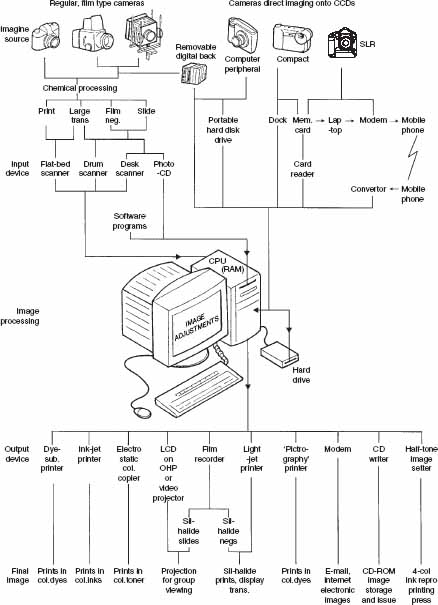
Figure 10.1 Some of the routes into, and out from, a digital computer workstation for production of images.
3. The mouse enables you to move a cursor or visual elements around the screen, ‘click’ onto a tool box icon, choose from the screen’s menu bar or select a command option. The computer keyboard, although less used, allows you some special commands and the ability to shortcut certain actions, as well as write in words to title image files, etc.
4. Peripheral devices include a drive for removable hard disks, and memory card reader. You might also have a graphics tablet and stylus as a higher precision substitute for the mouse. Some units – scanner, direct digital camera, printer – need connection to the computer through a USB2, FireWire or SCSI (pronounced ‘scuzzy’) interface. This is a small cabled device which allows high-speed communication of data between computer and peripheral.
Image processing
The computer is your image-processing workstation, but it only works given the electronic ‘tools’ provided by whatever software program you install (typically fed in from a CD-ROM or downloaded directly from the Internet). Once combined with the image(s) you have also input, software such as Adobe Photoshop sets out the picture on the monitor with a tool bar down one side and a range of options you can ‘pull down’ from a menu bar at the top.
Hundreds of changes – from subtle invisible mending to bizarre surrealist constructions are now possible. For example, you can remove colour casts, correct converging verticals, limit the depth of field or increase it by combination of multiple exposures, erase spots and blemishes, create high dynamic range images, introduce movement blur into chosen parts, etc.
Inputs
There are two ways of inputing images into a computer system: The first way is the direct camera imaging of your subject onto a charge-coupled device (CCD) or complementary metal-oxide semiconductor (CMOS) sensor – in other words use of a digital camera or digital back. A digital camera may be cabled direct to the computer, or record into the camera’s internal memory system or onto a memory card. The internal or card systems will later need to read image data into the computer via a camera cable, camera ‘docking’ unit or card reader. Digital data feedout from a camera back is wired direct into the computer memory system, or when working on location it can be captured using a battery-powered portable hard disk system. Bear in mind that high-resolution image capture systems create huge image files.
The second way is by digitizing printed photographic images or images on processed silver halide film. You can digitize images by one or more means. A film scanner will accept and digitize 35 mm or larger format positive or negative films. A flat-bed scanner digitizes prints, even rigid mounted prints, and many types handle transparencies too. Higher-end, although also much more expensive, a drum scanner will handle negatives or transparencies of practically all sizes and also (unmounted) prints (Figure 10.2). With all scan-in systems remember that you have to make the correct settings (pixels per inch) to suit the resolution of your intended print outputting device and planned image size (see page 212).

Figure 10.2 Scanners to convert silver halide images to digital data. A: scanner for individual 35 mm slides or negatives. B: flat-bed scanner, accepts reflective media such as prints up to A4. Most offer transmission illumination adaptors to accept film transparencies too. C: drum scanner. Film or (unmounted) prints are taped to revolving cylinder, lit by transmission or reflection.
Types of scanners
Preparing highest quality four-colour and other separations is still a specialist task. Some firms, such as service bureaux, specialize in ‘reproduction’ or ‘origination’ and then pass on their product as electronic files or film ready for other (printing) firms to use. Large printing houses have their own origination departments. At one time all this meant was that you, as a photographer, could regard your tasks as done and leave everything else to the experts. But developments in digital methods have progressed ‘down the line’ to the point where it is important for photographers to understand something of how scanners convert pictures to digital files. After all, scanners have become companions to desktop computer workstations. Recently the all-in-one devices which combine scanner, photocopier and printer are becoming more and more popular.
Drum scanners
The conversion of photographic originals into halftone separations was once done by copying through a large process camera. However, electronics first made possible the use of much more efficient drum scanner recorders (Figure 10.3). In drum scanners an original colour transparency or negative is taped to a clear perspex drum and rear-illuminated by a tiny point of light. An extension of the cylinder in a lightproof housing may carry the photographic process film ready to receive the four separation images.

Figure 10.3 Drum scanner, internal optics. Light from source (L), ducted along fibre optic tube, focuses on to tiny area of original transparency (T) taped around transparent drum. Drum rotates and optical section tracks through it to scan every part of the image. Transmitted light passes out to sensor unit also tracking alongside drum. Here three 45° semi-reflective mirrors split and direct light through R, G or B filters (F) on to photo-multiplier tubes. PMTs output analogue tricolour signals which then pass through an A/D converter.
As the cylinder rotates, the analysing light spot gradually moves along the cylinder, progressively scanning every part of the transparency. A colour-sensor unit with photomultiplier tubes (PMTs) to read red, green and blue (RGB) values tracks along in parallel outside the cylinder, turning the changing light values it receives into a long stream of electronic signals. This data is passed through an analog-to-digital (A/D) converter to turn it into a digital form and translated into screened colour separation signals by computer software programs. Meanwhile, at the exposing end of the cylinder a small beam of light focused on the separation film dims and brightens according to signals received. The exposing optics track along the rotating cylinder, gradually exposing each of the black and white film separations which will finally give cyan, magenta, yellow and black printing images.
The analysing unit (which, incidentally, also accepts prints, bouncing a light spot off the surface) feeds to the exposing unit through circuitry which allows the operator to carry out almost limitless contrast masking and dye-deficiency masking. The system will also electronically generate the required high-resolution dot shape to suit known printing/ink/ paper conditions. Most modern scanner/ recorders now have separate input and film exposing output halves (Figure 10.4). The scanner part can then produce digital files on computer hard disks or CD-ROMs which can be used for image distribution and use with a wide range of display and printout devices.

Figure 10.4 Schematic outline of components used for pre-press electronic scanning. Original colour transparency (T) is scanned by light source (L) in the input section. The four-colour signals produced can be stored and manipulated, then exposed in halftone dot form on to graphic arts film (F) in the light-tight output section. Normally a batch of originals are all scanned in at one time, light source and sensing system moving along the transparent cylinder (see Figure 10.3). Software programs adjust data between analysing and exposing stages, creating appropriate halftone screens, colour and contrast masking, etc. to achieve optimum separation images for the printing press.
Flat-bed (reflectance) scanners.
As a lower cost approach today’s compact flat-bed scanners and film scanners use CCDs instead of photomultiplier tubes. As Figure 10.5 shows, a typical flat-bed is about the size of a photographic lightbox with an A4 platen. It contains a linear array comprising a row of several thousand CCD elements which is used to scan any print or document placed face down on a top glass plate (Figure 10.6). During scanning a light source, a fluorescent lamp, and mirror unit gradually move down the length of the picture, reflecting lines of image data onto the CCD array in the base of the box. Some newer models incorporate a xenon gas cold cathode fluorescent lamp. Single pass colour scanners use arrays of filtered red, green and blue; others make three scans, each time changing the colour of the light. The analogue signals are then passed to an A/D converter for conversion to digital data. Some flatbeds include a light-transmitting optical system on their cover so you can scan-in film originals. All can give good results from large-format transparencies up to 8 10 in., but for 35 mm formats only the highest optical resolution (over 2000 pixels per inch) flat-bed scanner will do.

Figure 10.5 A flat-bed scanner has a glass-top surface where the hardcopy is placed for scanning.

Figure 10.6 Interior of flat-bed scanner. Original print, face down on glass top, is scanned by light from tubular source (T) which moves together with a mirror under the glass. From here light is reflected to a second, stationary, mirror and lens unit (L) down on to a linear CCD array.
Another technology used today for flat-bed scanners is the contact image sensor (CIS). It is based on red, green and blue light-emitting diodes (LEDs) and a row of sensors which has a width equal to the width of the scanning area, i.e. the glass plate. A scanner with CIS technology does not need an optical system, lamp and filters. The image is illuminated at a 45° angle by the red, green and blue LEDs and captured by the sensors. The CIS enables the scanner to be slimmer and lighter than a scanner with CCD sensors, costs less to manufacture because it does not incorporate an optical system and has lower power consumption. The technology is continuously improving and is approaching the accuracy and quality of CCD scanners.
Film/Transparency (transmission) scanners
Most desktop film scanners (Figure 10.7) are designed for 35 mm or for rollfilm size originals. There are also scanners which can scan films or transparencies of larger format. Some use a linear sensor – a row of filtered CCDs moving in steps across the rear-lit film (taking between 30 sec and 5 min per 35 mm frame) or one row of unfiltered CCDs making three passes with the light changed between RGB. In other types of film scanners, the CCD array is stationary and the film moves across the array. Alternatively the scanner has a matrix block CCD sensor, which is able to capture the full film image each time in a series of RGB exposures.

Figure 10.7 35 mm desktop scanner. Light from source (T) is reflected through the mounted film image, which slowly tracks under linear array CCD sensor.
Using a flat-bed or film scanner demands fewer skills than a drum unit, but you must still carefully use your computer to set the resolution of the scan (in pixels per inch) to suit the precise size and resolution of your intended print. Any later unforeseen change in this final aim will mean going back and rescanning your original.
Scanner characteristics
Resolution
The resolution of a scanner is measured in pixels per inch (ppi) or samples per inch (spi). You may also see resolution quoted in dots per inch (dpi) although this term refers mainly to printers or displays. In the technical specifications of scanners manufacturers quote the optical resolution of the scanner and in many cases the interpolated resolution. There is an important difference between them. The optical resolution of a scanner depends on the number of pixels in the CCD sensor. The amount of detail that can be recorded by the scanner is therefore limited by the optical resolution. The scanner driver however may give you the option for a higher scanning resolution than the optical. This is achieved by interpolation (see page 250). Interpolation increases the number of pixels in an image and therefore the file size but it does not add any more detail to the image. There are several types of interpolation (e.g. nearest neighbour, bilinear, bicubic) that give slightly different results. You may need however an output digital image with different pixel dimensions than those after scanning with optical resolution. If you want to have full control of the interpolation method, you can scan the film or print at the optical resolution and rescale it using image editing software, such as Adobe Photoshop, which gives you the option of selecting one of several different interpolation methods.
The output resolution varies depending on the type of scanner. Flat-bed scanners may provide an output optical resolution of 2400 ppi or higher, while the typical resolution of film scanners can range from 1000 ppi to 8000 ppi, depending on the maximum film format they can scan. The output resolution of a drum scanner is in the range 8000–12 000 ppi.
You will notice that manufacturers usually quote the optical resolution of scanners with two numbers. For example, 1200 1200 ppi. The first number refers to the number of the elements in the sensor array. The second number refers to the distance the sensor is moved to make the next reading. If the two numbers are different, for example 1200 2000 ppi, you should take the smallest number as the optical resolution.
Choosing the optimal scanning resolution
The optimal scanning resolution is based on the resolution of the output media (display or printer, for example) and is not always the highest that your scanner can give you. You should avoid high scanning resolution when it is not necessary because it can result in a large image file size. Note that the high resolution images will take up a lot of space in your computer’s hard disk. Storage can be an important factor to consider if you scan large volumes of images at a daily basis. Also remember that the manipulation of an image with a large file size will take longer. Depending on your work, this may have an effect on the productivity if you process a large number of images. Also, you will not necessarily gain higher image quality if the intended output media are of lower resolution. The additional information in the image may not be used in this case.
For example, if your image is going to be viewed on an Internet page, and displayed with the same dimensions as the original, a scanning resolution of 72 or 100 ppi is sufficient because it will be a close match to the display resolution (see page 220). As a general rule, calculate the pixel dimensions of your output image, taking into account its final dimensions and display or printing resolution. Then find the scanning resolution that will give you the same image pixel dimensions when you scan your original image (again taking into account the original’s physical dimensions).
Dynamic range
The dynamic range of a scanner represents the range of tones it can capture in an image. It is measured in a logarithmic scale and it is the difference between the optical density (OD) of the darkest shadows (Dmax) and the OD of the brightest highlights (Dmin). By knowing the dynamic range of your scanner you have information on the range of density values that it can distinguish. The minimum density value (Dmin) can be as low as 0 while the maximum value that Dmax can take is around 4.0. Owing to losses in the analogue to digital conversion the dynamic range may be lower than the estimated. Some manufacturers may quote the Dmax for the scanner instead of the dynamic range.
The dynamic range is also related to the bit depth of the scanner. A 48-bit scanner will have a higher dynamic range than a 24-bit scanner. Note that the dynamic range of the output digital image also depends on the dynamic range of the scanned film or print which may be lower or higher than the dynamic range of the scanner. In the latter case some tones in the film or print will not be accurately represented in the digital image. More effective use of the scanner dynamic range is made since the tonal range that the scanner can record will be adjusted accordingly.
Bit depth (or colour depth)
The bit depth defines the number of definable output colours (see page 238). A scanner driver may offer several options for the bit depth setting of the digitized film or print. For example, 1-bit (Black and White), 8-bit (Greyscale with 256 shades of grey) and 24-bit (True Colour – 16.7 million colours). Most models today offer an input bit depth of 48 bits but the output is generally reduced to 24 bits. The additional information is used by the scanner to avoid information loss during image adjustments (e.g. curve adjustments). Some scanners, however, provide the option of 48-bit output colour. Note that the scanner bit depth may be quoted as number of bits per channel (e.g. 8-bit/channel) or the total number of bits for all three channels (e.g. 24-bit).
The scanning mode you use affects the file size because it is related to the bit depth of the image. For example, a greyscale image is an 8-bit image (256 shades of grey) while a colour image may have 24-bit colour information or more.
Scanning speed
Scanning speed varies between models and it is an important parameter to consider if you scan large volumes of images because it affects the overall productivity. Technology has progressed since the earlier scanning devices. Scanning speed depends on the dimensions of the film or print and also on the scanning resolution. Typical time needed for a flat-bed scanner to scan, say, an A4 colour print at 300 ppi is 14 sec and at 600 ppi is 25 sec. For a 35 mm film, positive or negative, the flat-bed scanner may need 35–50 sec. A film scanner may need around 20–50 sec to scan a 35 mm film.
Setting up the scanner
The first step in setting up your scanner is to select a suitable location taking into account environmental conditions, such as humidity and extreme temperatures that may have an effect on the hardware. Power surges may damage the scanner electronic components so attach an uninterruptible power supply (UPS) device to maintain continuous electric power supply to the scanner. The same is recommended for the computer workstation as power surges may cause damage to the display.
The manufacturer should give detailed instructions on setting up the scanner such as connection to the computer and installing the appropriate software.
Image transfer
A scanner can be typically connected to a computer using four different methods: Parallel port, small computer system interface (SCSI), universal serial bus (USB) and FireWire (also known as IEEE-1394).
A connection to the parallel port of the computer is the slowest method of transferring images and is not used much today. The SCSI connection is significantly faster but it requires either a SCSI controller or a SCSI card in your computer. It has the advantage that you can connect multiple devices to a single SCSI port. For example, in SCSI 2, you can connect up to eight devices. Data rates with SCSI are very high. The latest Ultra SCSI standard provides data rates as high as 160 MB per second. SCSI can be complicated to configure, however. The parallel connection for scanners has now been largely replaced by the USB connection which is faster. The latest version is USB 2.0, and this standard is capable of transfer speeds of up to 60 MB per second, which is much higher than the 1.5 MB per second of the older USB 1.1 standard and 70 KB per second of the parallel connection. FireWire is faster than USB 1.0 and is comparable to earlier SCSI and to USB 2.0. It is used by scanners that have very high output resolutions which need faster transfer rate due to the high volume of data. USB is the most commonly used connection standard today and is used to connect a wide range of computer peripherals, including keyboards, mice, modems, scanners and cameras.
Scanner drivers
Scanners are supplied by the manufacturer with their own drivers that give you control over the scanning process. Drivers are programs that give you control over the scanner settings. You may also have the option to run your scanner through an imaging software package using the TWAIN driver provided by the manufacturer. The TWAIN standard (the word TWAIN is not an acronym) is the interface between the scanner hardware and the imaging software. It allows therefore communication between the scanner and different imaging software applications.
In many cases the functionality provided by the scanner application is independent of whether it is accessed as a standalone application or through an imaging software application using the TWAIN driver. In some cases the scanning application may give more flexibility and options than the TWAIN one. You can also use third-party scanning software.
The scanner driver often provides you with several options for setting the scanning parameters. If you are using a film scanner you have to set the appropriate film format and type (black and white, colour negative or colour positive). Some scanners also allow you to specify the film brand. The reason is that the colour characteristics of each film’s emulsion can differ and the scanner uses specific profiles for each film to compensate for this. Also do not forget that the colour negative film has an orange colour mask which the scanner has to take into account in order to produce correct colours. The scanning application may also give you the option to use custom profiles you may have created to scan your films thus enabling you to have full control of the output.

Figure 10.8 The scanner driver gives several options to adjust the tone scale of the image. You can for example adjust the curves or choose among settings that alter brightness or contrast. In this example, the first image (a) was scanned using the automatic mode while image and (b) was scanned using a ‘high contrast’ setting.
Other settings are the resolution, bit depth (colour/greyscale/black and white), brightness/contrast curves and colour balance (Figure 10.8). Some scanners allow you to set either the gamma of the scanner (measured in a similar way as the film gamma) or the gamma of the display (see page 219). Also you are usually given the option to use colour management and profiles and to select the output colour space (for example, sRGB, Adobe RGB, etc.).
When the film or print is scanned, you can save the digital RGB image as a TIFF, Bitmap, JPEG or PNG file (see page 240).
Driver features for automatic corrections
Manufacturers may provide additional features with the scanner driver for automatic corrections. One of these features is for the automatic removal of artefacts in the digital image arising from dust and scratches on the film. The method of detection is based on illuminating the film with infrared radiation. The location and size of the artefacts is then determined and the artefacts are removed using processing which combines this information with information from the surroundings obtained by scanning with white light. Other features include the restoration of colour saturation in discoloured or faded images, or shadow correction which may be required when images from a book are scanned.
Scanning films and prints
Before scanning your films or prints you must prepare their surfaces. If you are using a flat-bed scanner, you must also clean its glass plate. Dust or marks on the film or print surface will be recorded by the scanner and may appear in the digitized image. The same applies if there are dust or marks on the glass plate of the scanner. The effects are similar to dust and marks on the film surface or the glass film carrier when you are printing in a darkroom. Use a blow brush or compressed air to remove all dust from the surfaces of the print (or film). You can also clean the scanner glass plate with a special cleaner. If there are scratches on the film or print, however, you can remove them digitally using image editing software. Some scanners have a scratch-reduction feature that you can use to correct the problem, as previously mentioned.
If you are scanning films using a film or flat-bed scanner familiarize yourself with the film carrier and the way you load the film. Remember that when the film is scanned the emulsion should face the sensor (in a similar way that the emulsion of the film faces the light-sensitive surface (emulsion) of the paper when printing in the darkroom). One reason that film is loaded with the emulsion side facing the sensor is that the scanner optics are focused on the emulsion. Another reason is to avoid slight diffusion of the image. This occurs due to the fact that light would pass first through the emulsion and then the film base (which is thicker than the emulsion) before reaching the sensor.
When placing prints on the glass plate of a flat-bed scanner make sure that they are centred evenly over the surface. Remember that if the images you are scanning are on a thin paper which is printed on both sides, the text or other images which are printed on the rear face of the paper may be visible in the digital image. In this case it will be difficult to do corrections with an image editing software. Try using a black card to cover the paper. The image in the preview will appear darker but you can adjust brightness and contrast manually before scanning. If you scan printed halftone images you may get moiré patterns.
If you have both a film and a print of the same image it may be better to scan the film rather than the print, provided that you have access to a film scanner or a flat-bed scanner that produces high-quality film scans. The film is a first-generation image compared to the print which is a second-generation image. Inevitably some information is lost when the film is printed on paper due to differences in the colour balance (the colour of the print may not be an exact match to the colour in the film), dynamic range (the dynamic range of the paper is smaller than that of the film) or sharpness.
Scanning and copyright
When you scan any material, you must remember that its copyright is protected by law. So, unless you scan your own photographs or material for which you own the copyright, you have to ask the copyright owner for permission before you proceed to scanning and reproduction of the material. The laws on copyright give detailed information on your rights to reproduce or use material that is protected by copyright.
Image outputting – Displays
There are several means of outputting your images, such as displaying, printing (including film recording), storing in hard drives or CD-ROMs, DVD-ROMs, etc. When your digital images are displayed on a computer monitor, the image data output from your computer is in the form of a stream of binary digits (bits), which is converted by a display processor into a form suitable for the display device. The red, green and blue information for each pixel is stored in a frame buffer (memory) with size equal to the number of pixels in the image multiplied by the number of bits that are associated with each pixel. The output signal values from the memory to the display are processed via colour look-up tables (LUTs) and pass through the digital-to-analog converter (DAC). Three video signals, R, G and B, are formed and are input to the display. Computer displays are quoted with their diagonal size (e.g. 15 in., 17 in., etc.).
Cathode-ray tube displays (CRT)
The first large-scale applications of CRT display technology were for monochrome and, later, colour television and it was more recently adopted for computer colour display. The CRT display has a vacuum tube with an anode, a cathode and three electron guns. A layer of phosphors is on the inside front face of the tube, grouped in triads for the emission of red, green and blue signals, respectively. Each triad forms a pixel. The phosphors emit light when excited by an energy source. The input video signals cause emission of electrons from the cathode and an electron beam is produced from each electron gun. The beam is focused on the screen via a focusing system and deflected on the phosphor surface through a steel mask, called a shadowmask which has one hole for each RGB phosphor triad. This activates the phosphors which each emit red, green or blue light. The number of adjacent pixels on the area distinguished by a viewer defines the resolution of the display (Figure 10.9).
The smaller the distance (pitch) between two identically coloured dots the sharper the image is. The measurement of the pitch depends on the triad technology. In the literature the distance is often called dot pitch and refers to the dot triad technology. Note that the phosphors of a CRT age with time. This affects their colour and reduces the screen luminance.

Figure 10.9 Macro photograph of an image displayed on a CRT monitor. Note the RGB dots in the magnified part of the image.
There are several characteristics of the display system, such as the tone reproduction and gamma, the colour gamut, the white point and the colour bit depth setting of the graphics adapter which affect the quality of your displayed images.
Standards such as the Standard RGB (sRGB) colour space or models such as the gamma model have been originally developed based on the characteristics of the CRT displays and are currently being adapted for LCDs.
Liquid crystal displays (LCDs)
The liquid crystal displays are increasingly popular and are gradually replacing CRT displays for computer monitors. They are flat, thinner and lighter than the CRTs and have less power consumption. These properties have also made them suitable for portable computers. The most common LCD technology today is the twisted nematic active matrix LCDs (AMLCDs). An AMLCD consists of several components as illustrated in Figure 10.10. The light source is usually fluorescent, and depending on the manufacturer and the model, it can be located at the back, top or side of the display. The light passes through a diffuser which causes scattering. It produces a uniform illumination which passes through a rear polarizing filter. The transmitted light has one polarization only. It then passes through an element with thin film transistors (TFTs), which control each colour pixel of the screen, to the layer of liquid crystal elements. These elements have a twisted shape which rotates light at 90°. At this stage the light can pass through the front polarizer which is orthogonal to the rear polarizer. If voltage is applied to the liquid crystals their orientation changes and the amount of light that can pass through is reduced. The light is controlled by the applied voltage and the rotation of the liquid crystals can be reduced to 0° (the shape is not twisted any more). At this stage no light can pass through the polarizers.

Figure 10.10 (a) The liquid crystal elements (A) have a twisted shape which rotates light at 90°. At this stage the light can pass through the front polarizer (B) which is orthogonal to the rear polarizer (C) and the colour filter (D). (b) The light is controlled by the applied voltage. When the rotation of the liquid crystals is reduced to 0° (the shape is not twisted any more) no light can pass through the polarizers.
There are other technologies that do not use the twisted nematic system. One of them is the in-plane switching (IPS). It offers improvement regarding viewing angle, brightness and contrast.
In LCDs each pixel is covered by a group of three adjacent red, green and blue filters. There no distortions in the screen but the effect of viewing angle on image quality is significant.
Other display technologies
Other display technologies include plasma screens and organic light-emitting diode (OLED) displays. Plasma screens can be manufactured in large sizes. They have wide colour gamut (page 258), high dynamic range and there is no effect of viewing angle. OLEDs have a very wide viewing angle and can be manufactured as very thin or flexible displays.
Characteristics of display systems
Colour temperature (white point)
Display devices provide you with a range of options for setting the colour temperature, also referred to as the white point. You can select a preset white point, for example 5000 K, 5500 K, 6500 K, etc., and you may also be given the option of a custom setting where you can set the white point yourself with the aid of a calibration device. Your choice of white point depends on the application. For example, a recommended colour temperature for the graphic arts is 5000 K (CIE standard illuminant D50) while for photography it is 6500 K (CIE illuminant D65). If you use the sRGB colour space you should select the ‘sRGB’ white point preset, if available, or the 6500 K setting. The colour temperature also affects the range of colours relative to white within the display colour gamut boundary.
Tone reproduction
For CRT display systems, tone reproduction is described by a non-linear transfer function, which is approximately a power function. A simple equation that describes the CRT display system power function where the output display luminance (L) is plotted against the input pixel values (V) is the following:L V[H9253]. The exponent is called gamma ([H9253]), the same term that is used for conventional photography. The gamma of a CRT display may range usually between 1.8 and 2.4, with a typical value of 2.2 (Figure 10.11).
Because of the non-linear function, which is due to the physics of the CRT monitor, digital images which have been created with linear devices must be ‘corrected’ before being displayed. This is known as gamma correction. If they are not gamma corrected, they will appear dark on the screen. Gamma correction is carried out either in the image capture process or later with imaging software. When you scan an image, for example, the driver may give you the option to set the display gamma. The scanner has a linear transfer function, because the CCD sensors have a linear response. By giving information on your display gamma the driver corrects the image so that it will be displayed with the correct tonal scale on the screen. sRGB images are already ‘gamma corrected’ for a typical CRT display gamma of 2.2.
LCDs have a different, s-shaped, transfer function compared to the CRTs. With internal processing however their output mimics the function of the CRT display and is very close to a power function. This way images which are gamma corrected for viewing on a CRT display (for example sRGB images) are displayed correctly on LCDs with the same gamma setting.

Figure 10.11 The transfer function of a calibrated CRT display set to gamma equal to 2.2. LCDs mimic the transfer function of CRTs.
The gamma setting of different displays may vary and this depends on their luminance (brightness) and contrast settings. The result would affect the quality of displayed images. An image that was gamma corrected for a specific display gamma setting would appear darker if it was viewed on a display set to higher gamma and lighter if it was viewed on a display with lower gamma. You can calibrate your display to a specific gamma and colour temperature and create a profile (see page 260) using a calibration device. A simpler method is to use an application which will enable you to create a profile without the need for additional hardware. The profile may not be as accurate as a profile from calibration devices but it will be close enough.
Screen resolution
Resolution refers to the number of dots per inch (dpi) that the device can display and it depends on the dot size. Typical CRT display resolution is between 72 and 96 dpi. The term addressability, sometimes confused with resolution, refers to how many points can be addressed by the graphics card adapter. There are several settings for CRT displays (for example 1024 768 pixels and 1280 1024 pixels). Visually you may not see differences in image quality when changing the resolution on a CRT display, but you will notice that the image appears smaller when the display is set at a higher resolution and vice versa. The effect of resolution on image quality is scene dependent. For example, if an image has fine detail, some detail may be lost if it is displayed in lower resolution. LCDs have a specific number of pixels on the screen. The pixel dimensions of the LCD screen are referred to as its native resolution. You get optimal image quality only when the display resolution of the LCD is set to its native resolution. If you change the display resolution images, text may take on a slightly blurred appearance.
Colour gamut
The range of colours that can be reproduced by a computer display is described by its colour gamut. If the colour gamut of your image is outside the colour gamut of the display, the out of gamut colours will be clipped or mapped to the display gamut using a gamut-mapping technique (page 258). Your displayed image therefore may not faithfully reproduce the colours of your digital image. Colour management systems use profiles to ensure accurate colour reproduction throughout the imaging chain. Another solution is to use sRGB images (page 338). The sRGB standard was developed for accurate colour reproduction of images which are viewed on CRTs and it has the same gamut as a typical CRT display (see Figure 10.12).

Figure 10.12 The colour gamut of the sRGB colour space in the CIE 1931 xy chromaticity diagram.
Effect of viewing conditions
As described in Chapter 8, the ambient lighting and viewing conditions affect the way you perceive the colour and tonal quality of an image. This applies to displayed images as well as to printed or projected images. The ambient light may cause a reduction of contrast on the CRT or LCD screen due to flare. Some displays are equipped with a hood which isolates the viewing screen from the effect of ambient lighting. The perceived contrast of displayed images is also affected by the intensity of the ambient lighting and the viewing angle when they are displayed on an LCD.
Other parameters that may affect the perceived colour of the displayed images are colours of the image background and monitor surround due to colour adaptation of the observer’s visual system (see page 81). The same applies to the colour temperature of the ambient lighting. The intensity of the ambient lighting affects the perceived contrast of viewed images. For controlled results you should work with standardized daylight ambient illumination and a calibrated display system.
Display calibration
Calibration of your display is essential if you want accurate colour and tone reproduction of your displayed images. You should calibrate your display regularly if you want to have constant results. Remember to allow the display to warm up for about an hour before you start any calibration procedure.
Depending on the level of accuracy you need and your budget you can either invest in special calibration devices, such as the Macbeth Eye One or the ColorVision Spyder2 accompanied with the appropriate software (Figure 10.13) or conduct visual calibration using software with special test targets.

Figure 10.13 The Colorvision Spyder2PRO for monitor calibration with the Spyder PrintFIX PRO calibration device for printers.
You can use monitor calibration devices to set the target gamma and white point of your display. The devices have sensors which can measure the luminance and colour of your display, and this information is compared to the target values. You are then requested to carry out a set of adjustments on the luminance, contrast and colour of your device so that they match the target values. After the process is completed a profile is created for your display which you can use with colour management systems.
If you choose to use software for visual calibration, the result may not be as accurate as using a monitor calibration device but it may be sufficient for your applications. The calibration software provides you with a set of test targets which you use to correctly set the luminance and contrast of your monitor, thereby ensuring that you have the best results regarding the contrast of your displayed images. Some visual calibration software applications can create a profile for your display.
Visual adjustment of brightness and contrast is affected by the intensity of the ambient lighting and their settings give optimal results only under the ambient lighting conditions under which you performed the calibration. If the ambient lighting changes you have to perform the calibration again.
Image outputting – Digital printers
You can print out your final digital image from the computer in a wide range of ways. Digital colour printers – often desktop size – print onto paper using processes such as dye-sublimation or inkjet. You can also write to film, so forming a silver halide negative or transparency from which conventional colour prints are enlarged; or print direct onto a wide roll of silver halide paper or display film using a digitally modulated tri-colour laser system.
Printing by dye-sublimation
A good dye-sublimation printer produces continuous tone images and can output near-photographic quality colour images up to about A4 size (or Letter Size, in the US). As shown in Figure 10.14, these desktop machines use a full paper width donor ribbon carrying a series of (print size) areas of transparent cyan, magenta and yellow dye. In the print head a heating element, the width of the paper, vaporizes dye onto the paper surface so that after three passes the paper builds up a full colour image. The used donor ribbon with its remaining dyes winds onto a take-up spool and is later thrown away. You must use special paper – the action of the dyes then merge pixel dots together into pattern-free areas of colour and tone. A problem with dye-sublimation printing is the relatively high cost of donor ribbon and paper, plus litter from spent ribbons. An A4 colour print takes about 11.2 min to produce.

Figure 10.14 Thermal dye-sublimation printer, showing principle by which colour prints are output on paper from digital files. Receiving paper (P) fits under full-width roll of doner plastic coated with consecutive panels of cyan, magenta and yellow dyed wax. Sandwich passes under a bar of heated pins, each of which vaporizes and transfers tiny spots of colour according to scan data from image file. After each single colour is printed the wax roll shifts relative to the receiving paper, to bring its next colour into the same printing position and so build up a full colour print.
Printing by inkjet
These printers vary greatly in image quality and price (Figure 10.15). They range from desktop for A4-size prints, to expensive types of printing machine able to turn out mural size images on a range of sheet material including quality watercolour paper and acetate.
There are two technologies of inkjet printing: bubble jet, which is used by most printer manufacturers, and micro piezo (e.g. Epson). In bubble jet technology, each ink is forced into a tiny nozzle by heat. The heated ink forms a tiny bubble at the end of the nozzle which transfers, merging with others, to the image-receiving sheet. In the micro piezo technology, a piezo crystal becomes distorted when electric current is applied and the difference in pressure causes ink to be forced out of the nozzle. The size of the ink droplets is controlled by controlling the voltage applied on the piezo crystal, which results in different distortion. With this technology the size of droplets can vary depending on the detail of the image.
The ink droplets are measured in picolitres (1 picolitre is one trillionth of a litre) and today’s printers can produce droplets as small as 1–1.5 picolitres. The smallest they are the higher the resolution of the image.
When printing, the printing head of an inkjet printer moves rapidly backwards and forwards across the width of the print like the shuttle in a weaving machine, paper advancing minutely after each pass. Inkjet printers use the halftone method, which is explained in more detail in page 329. High-end inkjet printers can turn out excellent photographic quality images on a wide variety of papers (made for the purpose by most silver halide paper suppliers as well as paper manufacturers). They need careful maintenance however, including regular nozzle cleaning. For colour printing they use a set of cartridges. The number of inks depends on the manufacturer and it can range from four to twelve inks (e.g. Hewlett-Packard printers).
Colour inks
Inkjet printers traditionally printed using four colour inks, cyan, magenta, yellow and black, in one colour cartridge or individual cartridges for each colour. During the last years however manufacturers introduced additional colours to enhance the quality of printed colour images by reducing the visible artifacts of halftoning. There are, for example, six-colour printers, with the additional ‘light cyan’ and ‘light magenta’ colours, seven-colour printers which also include ‘light black’ ink, eight-colour printers (e.g. Epson) with one more addition, the ‘light light black’ etc. The addition of more than one black ink aims to enhance quality when printing greyscale images, where only black inks are used. Epson eight-colour printers, for example, incorporate a ‘photo black’ ink, for printing on glossy paper, and a ‘matte black’ ink when printing on matte paper. Other printers (e.g. Canon) use red and green inks in addition to the subtractive cyan, magenta and yellow.

Figure 10.15 An inkjet printer.
There are two types of inks, dye-based inks and pigment-based inks. The dye-based inks give more vivid colours than the pigment-based inks but they fade more quickly. The pigment-based inks are not as vivid. The colour gamut of the dye-based inks used to be wider than that of the pigment-based inks but today with the improvements in printing technology the gamuts are very close. Some printers may use dye-based inks for cyan, magenta and yellow and pigment-based inks for black. Canon printers, for example, use dye-based inks for cyan, magenta, yellow and black and pigment-based matte black ink.
Inkjet paper
There are several types of inkjet paper, each with a different finish (matt, semi-matt, glossy), weight, colour (white, bright white), resin coated or cotton, surface that looks like watercolour paper, etc. Because of all these differences between papers, the printer driver alters the colour saturation and the amount of ink deposited according to the paper used, to produce optimal results. It is essential therefore to select the right paper type for best printing results.
Printing quality and longevity of the prints also depend on the combination of inks and paper and are best when you use specific combinations of ink and paper. If you use inks and paper from different manufacturers, for example, you may notice differences in the print quality. You will need to do several tests with different paper types and finishes to find the ones that suit your work. Always remember to allow the ink to dry on the paper before handling, storing or framing it.
Printing by light
So called light-jet printers also use a moving printing head, but this issues a spot of light instead of inks, focused onto a roll of regular silver halide-coated photographic paper or display film in a light-tight consol unit (see Figure 10.16). The light spot is formed from the combined paths of three (RGB) laser sources, each one modulated by digital data from the computer. Light-jet printing must of course be followed by processing in machines with RA-4 chemistry or whatever is appropriate for the photographic material you used. This need, plus their high capital cost, means that light-jet printers are most often located in custom labs.

Figure 10.16 Light-jet printer: the light-tight cabinet is loaded with a 4 ft wide roll (P) of regular silver halide material – monochrome or colour paper, or display colour film. Image data from digital disk controls light intensity from R, G and B lasers which feed through mixing box (M) to a moving exposure head (H). This focuses the combined light into a tiny spot on the paper’s sensitive surface. Like an inkjet system the head moves backwards and forwards as the paper slowly rolls forward. A print 50 in. long takes 10 min to expose. It is then processed as if having been made normally using an enlarger.
Other digital colour printers such as Fuji’s ‘Pictrography’ expose the image with one pass of a row of tri-colour laser diodes onto a special light-sensitive donor paper. This is dampened with a small amount of water and heated to create a full colour dye image which is transferred under pressure and heat to a receiving paper. Some forms of laser printer machine function by using an electrostatic (Xerox type) drum. Instead of receiving its image optically, from an original placed face down on a glass plate, the digital data output from your computer controls light-emitting diodes or a laser beam which scans the image onto the electrically charged drum surface. The drum rotates, picking up coloured toner in areas unaffected by light and passing them on to receiving paper. Four passes (CMYK) are made in this way to build up a full colour print.
Printer characteristics
Printer resolution
The printer resolution is quoted in dots per inch (dpi). As mentioned in the section on scanners, you should take into account the printer resolution and the final dimensions of your image before scanning your film or print. You will not gain higher quality if you have a digital image with higher resolution than the output device. The additional information will not be used by the printer.
Typical good printer resolutions are in the range 1440 dpi–2880 dpi or higher. There is however a significant difference between printer resolution and digital image resolution. The printer resolution refers to the number of dots that the printer can print per inch, and not the pixels. The printer prints more than one dot per pixel (usually around 4 dots per pixel but this varies between printers) producing visually continuous tone. The image resolution needed for a good quality print is around 300 ppi. The printing speed varies, depending on the resolution, print dimensions, printing mode and paper type.

Figure 10.17 An example of dithering. The colours of a 24 bit image (a) are reduced to 256 colours. The images with reduced colours are (b) and (c). In image(b) the colours were not dithered while in image (c) you can see the effect of dithering using the method of error diffusion. The effect can be further observed in the magnified regions of the images.
Dithering
Dithering (similar to halftone) is a method used by non-continuous-tone printers to create all the colours of the digital image using a limited number of inks and more than one dot per pixel, as previously mentioned. You can read more about halftone in Chapter 14. With the dithering method a colour which does not exist in a palette is visually simulated by mixing dots of the existing colours that closely approximate it, using information from adjacent pixels. Similarly you can observe a dithering pattern on your display when you reduce the colour depth of a digital image from 24 bit to 8 bit and select the option to dither the colours (see Figure 10.17). There are several types of dithering such as error-diffusion, first developed by Floyd and Steinberg. Inkjet printers designed for printing photographs produce high-quality images where the dithering pattern is not visible, using a very small palette of colours.
Colour gamut
The colour gamut of a printer has a different shape from that of the display. The two gamuts do not match (see page 258) which means that some colours that are reproduced by the printer cannot be reproduced by the display. In the same way, some colours reproduced by the display cannot be reproduced by the printer. This is an important issue when you try to print images that you have edited by viewing them on a display. Colour alterations you made to the image may not be reproduced faithfully on the print. The solution to this problem is the use of colour management systems which apply gamut mapping. This is a method of mapping the out of gamut colours of one device to the gamut of the other device and by choosing the rendering indent you can control the type of conversion (e.g. perceptual, relative colorimetric, absolute colorimetric, etc.).
Printer drivers
The driver gives you several options to control the printer and also to perform maintenance such as alignment of the printer heads. Alignment is an important procedure for best printing quality and sharp images and it should be performed every time you change ink cartridges. Maintenance may also include nozzle checking and cleaning. Other options include the activation of colour management and the use of profiles, choice of paper type, print quality, printing speed. You may also have the option to adjust colours manually. More advanced options may give more control over adjustments and differ between manufacturers.
Effect of viewing conditions
The viewing conditions have an effect on the perceived colour and tone of the digital prints, in the same way that they affect the perceived quality of silver halide prints. When the prints are viewed with a dark surround the tones appear lighter than when viewed in a bright surround. It is useful to remember this effect when you frame and display your images. The finish of the paper (matt, semi-matt, glossy) also has an effect on the perceived tonal range of the printed image due to flare. The colour temperature of the ambient lighting is another parameter you should take into account. You must have standardized display and viewing conditions when you manipulate images on the screen and compare them with the print. Remember, however, that the colours of the screen cannot match perfectly the colours of the print. The image from the display is formed by transmitted light and red, green and blue colours while the image on the print is formed by reflected light and cyan, magenta, yellow and black inks.
You may also observe metamerism (see page 82) with some inks, causing the colours of the print to appear different under different lighting conditions. This may be more obvious if there is metamerism in a greyscale photograph which may appear with colour casts instead of a neutral tonal scale.
SUMMARY
![]() The computer setup consists of several components. Its central unit is the computer workstation which is connected to several peripheral devices. Computer software enables you to process images and alter their colour, correct converging verticals, remove marks, spots, blemishes and produce special effects.
The computer setup consists of several components. Its central unit is the computer workstation which is connected to several peripheral devices. Computer software enables you to process images and alter their colour, correct converging verticals, remove marks, spots, blemishes and produce special effects.
![]() The scanner is an input device which can digitize films or prints. There are different types of scanners: drum, flat-bed and film scanners. Drum scanners provide high resolution and overall quality. Technology of flat-bed and film scanners has improved and the digitization of images is of high quality. Some models of flatbed scanners can also scan film.
The scanner is an input device which can digitize films or prints. There are different types of scanners: drum, flat-bed and film scanners. Drum scanners provide high resolution and overall quality. Technology of flat-bed and film scanners has improved and the digitization of images is of high quality. Some models of flatbed scanners can also scan film.
![]() Scanning resolution is an important parameter. Always check for the optical resolution that is quoted by the manufacturer. Higher resolution than the optical is obtained via interpolation.
Scanning resolution is an important parameter. Always check for the optical resolution that is quoted by the manufacturer. Higher resolution than the optical is obtained via interpolation.
![]() When you scan your images choose the optimal resolution for your output device. Higher resolution than that will not improve the quality of your image. The output will not use the additional information.
When you scan your images choose the optimal resolution for your output device. Higher resolution than that will not improve the quality of your image. The output will not use the additional information.
![]() The dynamic range of the scanner represents the range of tones that the scanner can capture in an image. Some manufacturers may quote the maximum OD (Dmax). The bit depth defines the number of output colours. The scanner may scan at bit depth higher than 24 bits. The output image you will get however is usually in 24 bits.
The dynamic range of the scanner represents the range of tones that the scanner can capture in an image. Some manufacturers may quote the maximum OD (Dmax). The bit depth defines the number of output colours. The scanner may scan at bit depth higher than 24 bits. The output image you will get however is usually in 24 bits.
![]() There are four different types of scanner connections. The most common and fast connection is the USB2. The scanner can be accessed from your computer via its own driver or a TWAIN driver. With the TWAIN driver you access the scanner via an imaging software package. The driver allows you to set the scanning parameters.
There are four different types of scanner connections. The most common and fast connection is the USB2. The scanner can be accessed from your computer via its own driver or a TWAIN driver. With the TWAIN driver you access the scanner via an imaging software package. The driver allows you to set the scanning parameters.
![]() The two most common displays are the CRT display and the LCD. They have different technologies and properties. The display properties may affect the colour and tone of the displayed images.
The two most common displays are the CRT display and the LCD. They have different technologies and properties. The display properties may affect the colour and tone of the displayed images.
![]() The transfer function of the CRT monitor is non linear. Images can be displayed correctly on a CRT display when they are gamma corrected. This is performed either in the acquisition device or later using imaging software. sRGB images are gamma corrected. The LCDs apply internal processing to mimic the transfer function of the CRT displays.
The transfer function of the CRT monitor is non linear. Images can be displayed correctly on a CRT display when they are gamma corrected. This is performed either in the acquisition device or later using imaging software. sRGB images are gamma corrected. The LCDs apply internal processing to mimic the transfer function of the CRT displays.
![]() The viewing conditions affect the perceived tone and colour of displayed images. You should calibrate your display regularly for standardized results. Calibration can be conducted using calibration hardware or software.
The viewing conditions affect the perceived tone and colour of displayed images. You should calibrate your display regularly for standardized results. Calibration can be conducted using calibration hardware or software.
![]() There are several types of printers, such as dye-sublimation, inkjet, laser, pictography. They all use different technologies.
There are several types of printers, such as dye-sublimation, inkjet, laser, pictography. They all use different technologies.
![]() Inkjet printers use either the ‘bubble jet’ or the ‘micro piezo’ technology. They use four or more inks. Inks are dye or pigment based. Dye-based inks are more vivid than pigment based. Pigment-based inks have higher longevity.
Inkjet printers use either the ‘bubble jet’ or the ‘micro piezo’ technology. They use four or more inks. Inks are dye or pigment based. Dye-based inks are more vivid than pigment based. Pigment-based inks have higher longevity.
![]() There are several types of paper available. It is important to select the correct paper type in the printer driver for best results.
There are several types of paper available. It is important to select the correct paper type in the printer driver for best results.
![]() The printer resolution is quoted in dots per inch and refers to the number of dots that the printer can print per inch and not the pixels of the image. Halftone printers apply dithering.
The printer resolution is quoted in dots per inch and refers to the number of dots that the printer can print per inch and not the pixels of the image. Halftone printers apply dithering.
![]() The colour gamut of the display and the printer do not match. Gamut mapping is necessary to map the out of gamut colours of one device to the gamut of the other.
The colour gamut of the display and the printer do not match. Gamut mapping is necessary to map the out of gamut colours of one device to the gamut of the other.
![]() The perceived tone and colour of a print is affected by the ambient lighting conditions. You may also observe metamerism resulting from the inks, so the colours of your print may appear different when you view it under different lighting conditions.
The perceived tone and colour of a print is affected by the ambient lighting conditions. You may also observe metamerism resulting from the inks, so the colours of your print may appear different when you view it under different lighting conditions.
PROJECTS
1 In Adobe Photoshop open a 24-bit colour image and convert it to an 8-bit image (256 colours) from Menu Image Mode Indexed colours System (Mac OS or Windows), selecting the ‘None’ in the Dither options. Open again the 24-bit image and convert it to 8 bit but this time select ‘Diffusion’ from the Dither options. Observe the effect of dithering. Try the other dithering options (Pattern and Noise) and observe the different results.
2 Select a black and white image with medium contrast. Display it on your computer monitor, first with all the lights on in the room. Observe the tonal scale of the image. Turn all the lights off and view the image again. Observe the change in the perceived tones of the image.
3 Using Adobe Photoshop, open an image and rescale it at different, increasing levels using interpolation. Observe the blurring of the image when you increase too much the pixel dimensions. Interpolation just adds pixels in the image but no additional detail.