
Chapter 1. The Basics
Chapter One of this book contains Experiments 1 through 5.
In Experiment 1, I want you to get a taste for electricity—literally! You’ll experience electric current and discover the nature of electrical resistance, not just in wires and components but in the world around you.
Experiments 2 through 5 will show you how to measure and understand the pressure and flow of electricity—and finally, how to generate electricity with everyday items on a tabletop.
Even if you have prior knowledge of electronics, I encourage you to try these experiments before venturing into subsequent parts of the book. They’re fun, and they clarify some basic concepts.
Necessary Items for Chapter One
Each chapter of this book begins with pictures and descriptions of the tools, equipment, components, and supplies that will be required. After you have learned about them, you can flip to the back of the book where your buying options are summarized for quick reference.
-
To buy tools and equipment, see “Buying Tools and Equipment”.
-
For components, see “Components”.
-
For supplies, see “Supplies”.
-
If you prefer to get a prepackaged set of the components that you need, you have a choice of kits. See “Kits” for more information.
I classify tools and equipment as items that should be useful indefinitely. They range from pliers to a multimeter. Supplies, such as wire and solder, will gradually be consumed in a variety of projects, but the quantities that I am recommending should be sufficient for all the experiments in the book. Components will be listed for individual projects, and will become part of those projects.
The Multimeter
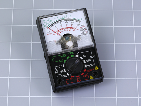
Figure 1-1. This kind of analog meter is inadequate for your purposes. You need a digital meter.
I’m beginning my instructional overview of tools and equipment with the multimeter, because I consider it the most essential piece of equipment. It will tell you how much voltage exists between any two points in a circuit, or how much current is passing through the circuit. It will help you to find a wiring error, and can also evaluate a component to determine its electrical resistance—or its capacitance, which is the ability to store an electrical charge.
If you’re starting with little or no knowledge, these terms may seem confusing, and you may feel that a multimeter looks complicated and difficult to use. This is not the case. It makes the learning process easier, because it reveals what you cannot see.
Before I discuss which meter to buy, I can tell you what not to buy. You don’t want an old-school meter with a needle that moves across a scale, as shown in Figure 1-1. That is an analog meter.
You want a digital meter that displays values numerically—and to give you an idea of the equipment available, I have selected four examples.
Figure 1-2 shows the cheapest digital meter that I could find, costing less than a paperback novel or a six-pack of soda. It cannot measure very high resistances or very low voltages, its accuracy is poor, and it does not measure capacitance at all. However, if your budget is very tight, it will probably see you through the experiments in this book.
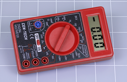
Figure 1-2. The cheapest meter that I could find.
The meter in Figure 1-3 offers more accuracy and more features. This meter, or one similar to it, is a good basic choice while you are learning electronics.
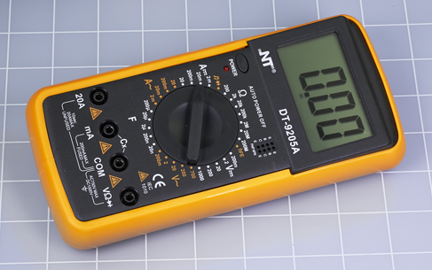
Figure 1-3. Any meter similar to this one is a good basic choice.
The example in Figure 1-4 is slightly more expensive but much better made. This particular model has been discontinued, but you can find many like it, probably costing two to three times as much as the NT brand in Figure 1-3. Extech is a well-established company trying to maintain its standards in the face of cut-price competitors.

Figure 1-4. A better-made meter at a somewhat higher price.
Figure 1-5 shows my personal preferred meter at the time of writing. It is physically rugged, has all the features I could want, and measures a wide range of values with extremely good accuracy. However, it costs more than twenty times as much as the lowest-priced, bargain-basement product. I regard it as a long-term investment.
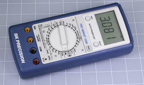
Figure 1-5. A high-quality product.
How do you decide which meter to buy? Well, if you were learning to drive, you wouldn’t necessarily need a high-priced car. Similarly, you don’t need a high-priced meter while you are learning electronics. On the other hand, the absolute cheapest meter may have some drawbacks, such as an internal fuse that is not easily replaceable, or a rotary switch with contacts that wear out quickly. So here’s a rule of thumb if you want something that I would regard as inexpensive but acceptable:
-
Search eBay for the absolute cheapest model you can find, then double the price, and use that as your guideline.
Regardless of how much you spend, the following attributes and capabilities are important.
Ranging
A meter can measure so many values, it has to have a way to narrow the range. Some meters have manual ranging, meaning that you turn a dial to choose a ballpark for the quantity that interests you. A range could be from 2 to 20 volts, for instance.
Other meters have autoranging, which is more convenient, because you just connect the meter and wait for it to figure everything out. The key word, however, is “wait.” Every time you make a measurement with an autoranging meter, you will wait a couple of seconds while it performs an internal evaluation. Personally I tend to be impatient, so I prefer manual meters.
Another problem with autoranging is that because you have not selected a range yourself, you must pay attention to little letters in the display where the meter is telling you which units it has decided to use. For example, the difference between a “K” or an “M” when measuring electrical resistance is a factor of 1,000. This leads me to my personal recommendation:
-
I suggest you use a manual-ranging meter for your initial adventures. You’ll have fewer chances to make errors, and it should cost slightly less.
A vendor’s description of a meter should say whether it uses manual ranging or autoranging, but if not, you can tell by looking at a photograph of its selector dial. If you don’t see any numbers around the dial, it’s an autoranging meter. The meter in Figure 1-4 does autoranging. The others that I pictured do not.
Values
The dial will also reveal what types of measurements are possible. At the very least, you should expect:
Volts, amps, and ohms, often abbreviated with the letter V, the letter A, and the ohm symbol, which is the Greek letter omega, shown in Figure 1-6. You may not know what these attributes mean right now, but they are fundamental.
Your meter should also be capable of measuring milliamps (abbreviated mA) and millivolts (abbreviated mV). This may not be immediately clear from the dial on the meter, but will be listed in its specification.

Figure 1-6. Three samples of the Greek symbol omega, used to represent electrical resistance.
DC/AC, meaning direct current and alternating current. These options may be selected with a DC/AC pushbutton, or they may be chosen on the main selector dial. A pushbutton is probably more convenient.
Continuity testing. This useful feature enables you to check for bad connections or breaks in an electrical circuit. Ideally it should create an audible alert, in which case it will be represented symbolically with a little dot that has semicircular lines radiating from it, as shown in Figure 1-7.

Figure 1-7. This symbol indicates the option to test a circuit for continuity, with audible feedback. It’s a very useful feature.
For a small additional sum, you should be able to buy a meter that makes the following measurements. In order of importance:
Capacitance. Capacitors are small components that are needed in the majority of electronic circuits. Because small ones usually don’t have their values printed on them, the ability to measure their values can be important, especially if some of them get mixed up or (worse) fall on the floor. Very cheap meters usually cannot measure capacitance. When the feature exists, it is usually indicated with a letter F, meaning farads, which are the units of measurement. The abbreviation CAP may also be used.
Transistor testing, indicated by little holes labeled E, B, C, and E. You plug the transistor into the holes. This enables you to verify which way up the transistor should be placed in a circuit, or if you have burned it out.
Frequency, abbreviated Hz. This is unimportant in the experiments in this book, but may be useful if you go further.
Any features beyond these are not significant.
If you still feel unsure about which meter to buy, read ahead a little to get an idea of how you will be using a meter in Experiments 1, 2, 3, and 4.
Safety Glasses
For Experiment 2, you may want to use safety glasses. The cheapest plastic type is satisfactory for this little adventure, as the risk of a battery bursting is almost nonexistent, and probably would not occur with much force.
Regular eyeglasses would be an acceptable substitute, or you could view the experiment through a little piece of transparent plastic (for instance, you can cut out a piece of a water bottle).
Batteries and Connectors
Because batteries and connectors become part of a circuit, I am categorizing them as components. See “Other Components” for details about ordering these parts.
Almost all the experiments in this book will use a power source of 9 volts. You can obtain this from a basic nine-volt battery sold in supermarkets and convenience stores. Later I’ll suggest an upgrade to an AC adapter, but you don’t need that right now.
For Experiment 2, you will need a couple of 1.5-volt AA batteries. These have to be the alkaline type. You must not perform this experiment with any kind of rechargeable battery.
To transfer the power from a battery into a circuit, you need a connector for the 9-volt battery, as shown in Figure 1-8, and a carrier for a single AA battery, as shown in Figure 1-9. One carrier will be enough, but I suggest you get at least three 9-volt connectors for future use.

Figure 1-8. Connector to deliver power from a 9-volt battery.
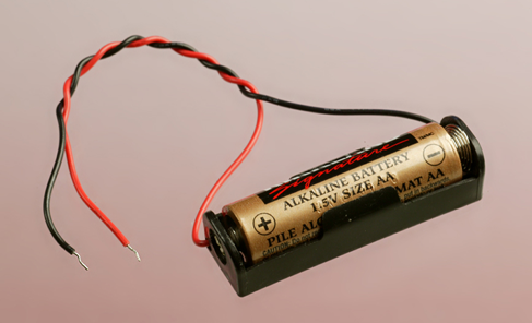
Figure 1-9. You need a carrier like this for a single AA battery. Don’t buy the type of carrier that holds two batteries (or three, or four).
Test Leads
You will use test leads (pronounced “leeds”) to connect components with each other in the first few experiments. The type of leads I mean are double-ended. Surely, any piece of wire has two ends, so why should it be called “double-ended”? The term usually means that each end is fitted with an alligator clip as shown in Figure 1-10. Each clip can make a connection by grabbing something and gripping it securely, freeing you to use your hands elsewhere.
You don’t want the kind of test leads that have a plug at each end. Those are sometimes known as jumper wires.

Figure 1-10. Double-ended test leads with an alligator clip at each end.
Test leads are classified as equipment for the purposes of this book. See “Buying Tools and Equipment” for more information.
Potentiometer
A potentiometer functions like the volume control on an old-fashioned stereo. The kinds shown in Figure 1-11 are considered large by modern standards, but large is what you need, because you’ll be gripping the terminals with the alligator clips on your test leads. A 1” diameter potentiometer is preferred. Its resistance should be listed as 1K. If you are buying your own, see “Other Components” for details.

Figure 1-11. Potentiometers of the general type required for your first experiments.
Fuse
A fuse interrupts a circuit if too much electricity passes through it. Ideally you’ll buy the type of 1-amp automotive fuse shown in Figure 1-12, which is easy to grip with test leads, and clearly reveals the element inside it. Automotive fuses are sold in a variety of physical sizes, but so long as you use one rated for 1 amp, the dimensions don’t matter. Buy three to allow for destroying them intentionally or accidentally. If you don’t want to use an auto parts supplier, a 2AG-size 1-amp glass cartridge fuse of the kind shown in Figure 1-13 will be available from electronics component suppliers, although it is not quite so easy to use.
Feedback from readers has taught me that quality control of fuses is very poor. Some 1-amp fuses don’t blow until you pass two or three amps through them. This is another reason why you should buy two or three fuses, if possible.
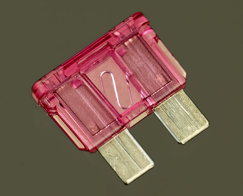
Figure 1-12. This type of automotive fuse is easier to handle than the cartridge fuses used in electronics hardware.

Figure 1-13. You can use a cartridge fuse like this, although your alligator clips won’t grip it so easily.
Light-Emitting Diodes
More commonly known as LEDs, they come in various shapes and forms. The ones we will be using are properly known as LED indicators, and are often described as standard through-hole LEDs in catalogs. A sample in Figure 1-14 is 5mm in diameter, but 3mm is sometimes easier to fit into a circuit when space is limited. Either will do.

Figure 1-14. A light-emitting diode (LED) approximately 5mm in diameter.
Throughout this book I will refer to generic LEDs, by which I mean the cheapest ones that don’t emit a high-intensity light and are commonly available in red, yellow, or green. They are often sold in bulk quantities, and are used in so many applications that I suggest you buy at least a dozen of each color.
Some generic LEDs are encapsulated in “water clear” plastic or resin, but emit a color when power is applied. Other LEDs are encapsulated in plastic or resin tinted with the same color that they will display. Either type is acceptable.
In a few experiments, low-current LEDs are preferred. They cost slightly more, but are more sensitive. For example, in Experiment 5, where you will generate a small amount of current with an improvised battery, you’ll get better results with a low-current LED. See “Other Components” for additional guidance, if you are not using components that were supplied in a kit.
Resistors
You’ll need a variety of resistors to restrict the voltage and current in various parts of a circuit. They should look something like the ones in Figure 1-15. The color of the body of the resistor doesn’t matter. Later I will explain how the colored stripes tell you the value of the component.

Figure 1-15. Two resistors of the type you need, all rated for 1/4 watt.
If you are buying your own resistors, they are so small and cheap, you would be foolish to select just the values listed in each experiment. Get a prepackaged selection in bulk from surplus or discount sources, or eBay. For more information about resistors, including a complete list of all the values used throughout this book, see “Components”.
You don’t need any other components to take you through Experiments 1 through 5. So let’s get started!
Experiment 1: Taste the Power!
Can you taste electricity? It feels as if you can.
What You Will Need
-
9-volt battery (1)
-
Multimeter (1)
That’s all!
Caution: No More than Nine Volts
This experiment should only use a 9-volt battery. Do not try it with a higher voltage, and do not use a bigger battery that can deliver more current. Also, if you have metal braces on your teeth, be careful not to touch them with the battery. Most important, never apply electric current from any size of battery through a break in your skin.
Procedure
Moisten your tongue and touch the tip of it to the metal terminals of a 9-volt battery, as shown in Figure 1-16. (Maybe your tongue isn’t quite as big as the one in the picture. Mine certainly isn’t. But this experiment will work regardless of how big or small your tongue may be.)

Figure 1-16. An intrepid Maker tests the characteristics of an alkaline battery.
Do you feel that tingle? Now set aside the battery, stick out your tongue, and dry the tip of it very thoroughly with a tissue. Touch the battery to your tongue again, and you should feel less of a tingle.
What’s happening here? You can use a meter to find out.
Setting Up Your Meter
Does your meter have a battery preinstalled? Select any function with the dial, and wait to see if the display shows a number. If nothing is visible, you may have to open the meter and put in a battery before you can use it. To find out how to do this, check the instructions that came with the meter.
Meters are supplied with a red lead and a black lead. Each lead has a plug on one end, and a steel probe on the other end. You insert the plugs into the meter, then touch the probes on locations where you want to know what’s going on. See Figure 1-17. The probes detect electricity; they don’t emit it in significant quantities. When you are dealing with the small currents and voltages in the experiments in this book, the probes cannot hurt you (unless you poke yourself with their sharp ends).
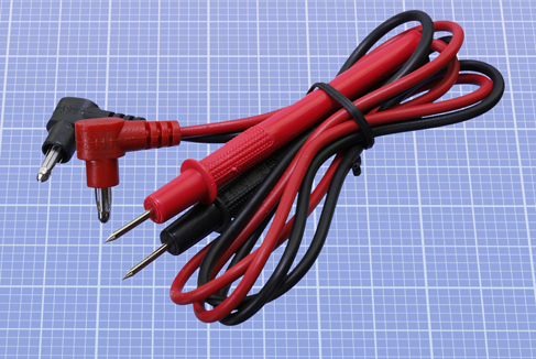
Figure 1-17. Leads for a meter, terminating in metal probes.
Most meters have three sockets, but some have four. See Figure 1-18, Figure 1-19, and Figure 1-20 for examples. Here are the general rules:
-
One socket should be labelled COM. This is common to all your measurements. Plug the black lead into this socket, and leave it there.
-
Another socket should be identified with the ohm (omega) symbol, and the letter V for volts. It can measure either resistance or voltage. Plug the red lead into this socket.
-
The voltage/ohms socket may also be used for measuring small currents in mA (milliamps) . . . or you may see a separate socket for this, which will require you to move the red lead sometimes. We’ll get to that later.
-
An additional socket may be labelled 2A, 5A, 10A, 20A, or something similar, to indicate a maximum number of amps. This is used for measuring high currents. We won’t be needing it for projects in this book.
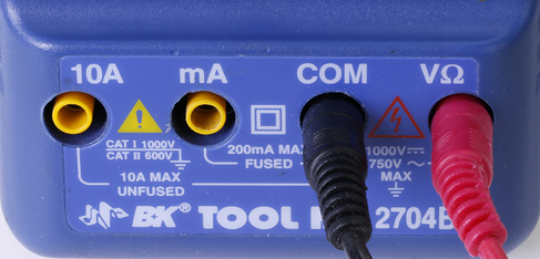
Figure 1-18. Note the labeling of sockets on this meter.
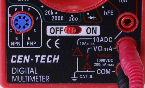
Figure 1-19. Socket functions are split up differently on this meter.
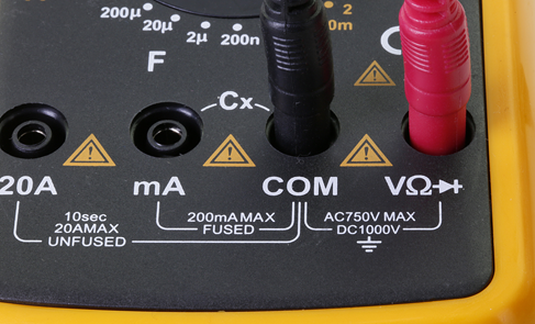
Figure 1-20. Sockets on one more meter.
Fundamentals: Ohms
You’re going to evaluate the resistance of your tongue, in ohms. But what is an ohm?
We measure distance in miles or kilometers, mass in pounds or kilograms, and temperature in Fahrenheit or Centigrade. We measure electrical resistance in ohms, which is an international unit named after Georg Simon Ohm, who was an electrical pioneer.
The Greek omega symbol indicates ohms, but for resistances above 999 ohms the uppercase letter K is used, which means kilohm, equivalent to a thousand ohms. For example, a resistance of 1,500 ohms will be referred to as 1.5K.
Above 999,999 ohms, the uppercase letter M is used, meaning megohm, which is a million ohms. In everyday speech, a megohm is often referred to as a “meg.” If someone is using a “two-point-two meg resistor,” its value will be 2.2M.
A conversion table for ohms, kilohms, and megohms is shown in Figure 1-21.

Figure 1-21. Conversion table for the most common multiples of ohms.
-
In Europe, the letter R, K, or M is substituted for a decimal point, to reduce the risk of errors. Thus, 5K6 in a European circuit diagram means 5.6K, 6M8 means 6.8M, and 6R8 means 6.8 ohms. I won’t be using the European style here, but you may find it in some circuit diagrams elsewhere.
A material that has very high resistance to electricity is known as an insulator. Most plastics, including the colored sheaths around wires, are insulators.
A material with very low resistance is a conductor. Metals such as copper, aluminum, silver, and gold are excellent conductors.
Measuring Your Tongue
Inspect the dial on the front of your meter, and you’ll find at least one position identified with the ohm symbol. On an autoranging meter, turn the dial to point to the ohm symbol as shown in Figure 1-22, touch the probes gently to your tongue, and wait for the meter to choose a range automatically. Watch for the letter K in the numeric display. Never stick the probes into your tongue!
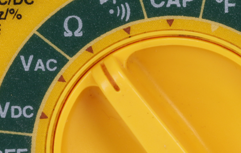
Figure 1-22. On an autoranging meter, just turn the dial to the ohm (omega) symbol.
On a manual meter, you must choose a range of values. For a tongue measurement, probably 200K (200,000 ohms) would be about right. Note that the numbers beside the dial are maximums, so 200K means “no more than 200,000 ohms” while 20K means “no more than 20,000 ohms.” See the close-ups of the manual meters in Figure 1-23 and Figure 1-24.
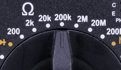
Figure 1-23. A manual meter requires you to select the range.

Figure 1-24. A different manual meter dial, but the principle is the same.
Touch the probes to your tongue about one inch apart. Note the meter reading, which should be around 50K. Put aside the probes, stick out your tongue, and use a tissue to dry it carefully and thoroughly, as you did before. Without allowing your tongue to become moist again, repeat the test, and the reading should be higher. Using a manual ranging meter, you may have to select a higher range to see a resistance value.
-
When your skin is moist (for instance, if you perspire), its electrical resistance decreases. This principle is used in lie detectors, because someone who knowingly tells a lie, under conditions of stress, may tend to perspire.
Here’s the conclusion that your test may suggest. A lower resistance allows more electric current to flow, and in your initial tongue test, more current created a bigger tingle.
Fundamentals: Inside a Battery
When you used a battery for the original tongue test, I didn’t bother to mention how a battery works. Now is the time to rectify that omission.
A 9-volt battery contains chemicals that liberate electrons (particles of electricity), which want to flow from one terminal to the other as a result of a chemical reaction. Think of the cells inside a battery as being like two water tanks—one of them full, the other empty. If the tanks are connected with each other by a pipe and a valve, and you open the valve, water will flow between them until their levels are equal. Figure 1-25 may help you to visualize this. Similarly, when you open up an electrical pathway between the two sides of a battery, electrons flow between them, even if the pathway consists only of the moisture on your tongue.
Electrons flow more easily through some substances (such as a moist tongue) than others (such as a dry tongue).

Figure 1-25. You can think of a battery as being like a pair of interconnected water reservoirs.
Further Investigation
The tongue test was not a very well-controlled experiment, because the distance between the probes might have varied a little between one trial and the next. Do you think that may be significant? Let’s find out.
Hold the meter probes so that their tips are only 1/4” apart. Touch them to your moist tongue. Now separate the probes by 1” and try again. What readings do you get?
When electricity travels through a shorter distance, it encounters less resistance. As a result, the current will increase.
Try a similar experiment on your arm, as shown in Figure 1-26. You can vary the distance between the probes in fixed steps, such as 1/4”, and note the resistance shown by your meter. Do you think that doubling the distance between the probes doubles the resistance shown by the meter? How can you prove or disprove this?
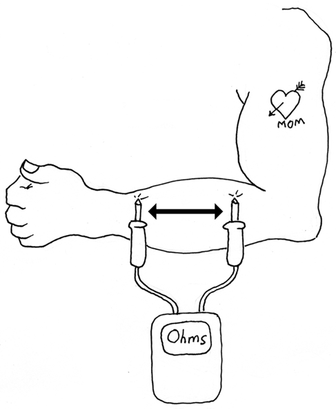
Figure 1-26. Vary the distance between the probes, and note the reading on your meter.
If the resistance is too high for your meter to measure, you will see an error message, such as L, instead of some numbers. Try moistening your skin, then repeat the test, and you should get a result. The only problem is, as the moisture on your skin evaporates, the resistance will change. You see how difficult it is to control all the factors in an experiment. The random factors are properly known as uncontrolled variables.
There is still one more variable that I haven’t discussed, which is the amount of pressure between each probe and the skin. If you press harder, I suspect that the resistance will diminish. Can you prove this? How could you design an experiment to eliminate this variable?
If you’re tired of measuring skin resistance, you can try dunking the probes into a glass of water. Then dissolve some salt in the water, and test it again. No doubt you’ve heard that water conducts electricity, but the full story is not so simple. Impurities in water play an important part.
What do you think will happen if you try to measure the resistance of water that contains no impurities at all? Your first step would be to obtain some pure water. So-called purified water usually has minerals added after it was purified, so, that’s not what you want. Similarly, spring water is not totally pure. What you need is distilled water, also known as deionized water. This is often sold in supermarkets. I think you’ll find that its resistance, per inch between the meter probes, is higher than the resistance of your tongue. Try it to find out.
Those are all the experiments relating to resistance that I can think of, right now. But I still have a little background information for you.
Background: The Man Who Discovered Resistance
Georg Simon Ohm, pictured in Figure 1-27, was born in Bavaria in 1787 and worked in obscurity for much of his life, studying the nature of electricity using metal wire that he had to make for himself (you couldn’t truck on down to Home Depot for a spool of hookup wire back in the early 1800s).
Despite his limited resources and inadequate mathematical abilities, Ohm was able to demonstrate in 1827 that the electrical resistance of a conductor such as copper varied in inverse proportion with its area of cross-section, and the current flowing through it is proportional to the voltage applied to it, so long as temperature is held constant. Fourteen years later, the Royal Society in London finally recognized the significance of his contribution and awarded him the Copley Medal. Today, his discovery is known as Ohm’s Law. I’ll explain more about this in Experiment 4.

Figure 1-27. Georg Simon Ohm, after being honored for his pioneering work, most of which he pursued in relative obscurity.
Cleanup and Recycling
Your battery should not have been damaged or significantly discharged by this experiment. You can use it again.
Remember to switch off your meter before putting it away. Many meters will beep to remind you to switch them off if you don’t use them for a while, but some don’t. A meter consumes a very small amount of electricity while it is switched on, even when you are not using it to measure anything.
Experiment 2: Let’s Abuse a Battery!
To get a better feeling for electrical power, you’re going to do what most books tell you not to do. You’re going to short out a battery. (A short circuit is a shortcut between two sides of a power source.)
Caution: Use a Small Battery
The experiment that I am going to describe is safe, but some short circuits can be dangerous. Never short out a power outlet in your home: there’ll be a loud bang, a bright flash, and the wire or tool that you use will be partially melted, while flying particles of melted metal can burn you or blind you.
If you short out a car battery, the flow of current is so huge that the battery might even explode, drenching you in acid. Just ask the guy in Figure 1-28 (if he is able to answer).

Figure 1-28. Dropping a wrench between the terminals of a car battery will be bad for your health. Short circuits can be dramatic, even at a “mere” 12 volts, if the battery is big enough.
Lithium batteries are often found in power tools, laptop computers, and other portable devices. Never short-circuit a lithium battery: it can catch fire and burn you. Lithium batteries have been known to catch fire even if you don’t short them out, as shown in Figure 1-29. After some early laptops self-destructed, lithium battery packs were modified to prevent this kind of thing. But short-circuiting them is still a very bad idea.
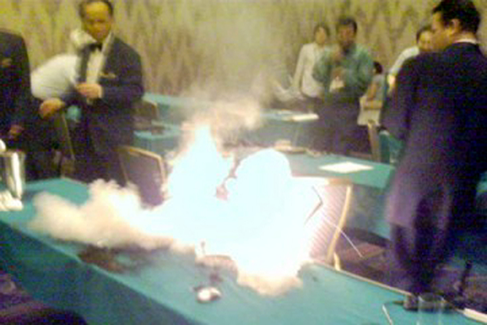
Figure 1-29. Never fool around with lithium batteries.
Use only an alkaline battery in this experiment, and only a single AA cell. You may also want to wear safety glasses in case you happen to have a defective battery.
What You Will Need
-
1.5-volt AA battery (2)
-
Battery carrier (1)
-
1-amp fuse (2)
-
Safety glasses (regular eyeglasses or sunglasses will do)
-
Test leads with alligator clips at each end (2)
Generating Heat with Current
Use an alkaline battery. Do not use any kind of rechargeable battery.
Put the battery into a battery carrier that terminates in two thin wires, as shown in Figure 1-9. Twist the bare ends of the wires together, as shown in Figure 1-30. At first it seems that nothing happens. But wait one minute, and you’ll find that the wires are getting hot. Wait another minute, and the battery, too, will be hot.

Figure 1-30. Shorting out an alkaline battery can be safe if you follow the directions precisely.
The heat is caused by electricity flowing through the wires and through the electrolyte (the conductive fluid) inside the battery. If you’ve ever used a hand pump to force air into a bicycle tire, you know that the pump gets warm. Electricity behaves in much the same way. You can imagine the electricity being composed of particles (electrons) that make the wire hot as they push through it. This isn’t a perfect analogy, but it’s close enough for our purposes.
Where do the electrons come from? Chemical reactions inside the battery liberate them, creating electrical pressure. The correct name for this pressure is voltage, which is measured in volts and is named after Alessandro Volta, another electrical pioneer.
Going back to the water analogy: the height of the water in a tank is proportional with the pressure of the water, and is similar to voltage. Figure 1-31 may help you to visualize this.

Figure 1-31. The pressure in a source of water is analogous to the voltage in a source of electricity.
But volts are only half of the story. When electrons flow through a wire, the amount of flow during a period of time is known as amperage, named after yet another electrical pioneer, André-Marie Ampère. That flow is also generally known as current. The current—the amperage—generates the heat.
-
Think of voltage as pressure.
-
Think of amperes as the rate of flow, properly known as current.
Background: Why Didn’t Your Tongue Get Hot?
When you touched the 9-volt battery to your tongue, you felt a tingle, but no perceptible heat. When you shorted out a battery, you generated a noticeable amount of heat, even though you only used a 1.5-volt battery. How can you explain this?
Your meter showed you that the electrical resistance of your tongue is very high. This high resistance reduced the flow of electrons.
The resistance of a wire is very low, so if there’s a wire connecting the two terminals of the battery, more current will pass through it than passed through your tongue, and it will create more heat. If all other factors remain constant:
-
Lower resistance allows more current to flow.
-
The heat generated by electricity is proportional with the amount of electricity (the current) passing through a conductor in a period of time. (This relationship is no longer exactly true if the resistance of the wire changes as the wire gets hot. But it remains approximately true.)
Here are some other basic concepts:
-
The flow of electricity per second is measured in amperes, very commonly abbreviated as amps.
-
The pressure of electricity that causes the flow is measured in volts.
-
The resistance to the flow is measured in ohms.
-
A higher resistance restricts the current.
-
A higher voltage is better able to overcome resistance and increase the current.
The relationship between voltage, resistance, and amperage (pressure, resistance, and flow) is illustrated in Figure 1-32.

Figure 1-32. Resistance blocks pressure and reduces flow—in water, and in electricity.
Fundamentals: Volt Basics
The volt is an international unit, represented by an uppercase letter V. In the United States and a few other countries, AC power for domestic use is supplied at 110V, 115V, or 120V, with separate circuits for heavy-duty appliances delivering 220V, 230V, or 240V. Solid-state electronic components traditionally required DC power ranging from 5V to about 20V, although modern surface-mount devices may use less than 2V. Some components, such as a microphone, deliver voltage measured in millivolts, abbreviated mV, each millivolt being 1/1,000th of a volt. When electricity is distributed over long distances, it is measured in kilovolts, abbreviated kV. A few long-distance lines use megavolts. A conversion table for millivolts, volts, and kilovolts is shown in Figure 1-33.
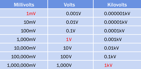
Figure 1-33. Conversion table for the most common multiples of volts.
Fundamentals: Ampere Basics
The ampere is an international unit, represented by an uppercase letter A. Household appliances may draw several amps, and a typical circuit breaker in the United States is rated for 20A. Electronic components often are rated in milliamps, abbreviated mA, each milliamp being 1/1,000th of an amp. Devices such as liquid-crystal displays may draw microamps, abbreviated µA, each microamp being 1/1,000th of a milliamp. A conversion table for amps, milliamps, and microamps is shown in Figure 1-34.
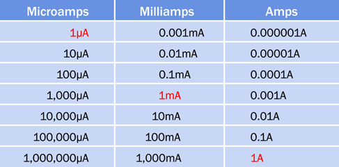
Figure 1-34. Conversion table for the most common multiples of amps.
How to Blow a Fuse
Exactly how much current flowed through the wires of the battery carrier, when you shorted out the battery? Could we have measured it?
Not easily, because if you try to use your multimeter to measure high current, you may blow the fuse inside the meter. So set aside the meter, and we’ll use your 1-amp fuse, which we can sacrifice because it didn’t cost very much.
First inspect the fuse, using a magnifying glass, if you have one. In an automotive fuse, you should see a tiny S-shape in the transparent window at the center. That S is a thin section of metal that melts easily. You saw it in Figure 1-12. In a glass cartridge fuse, there’s a thin piece of wire that serves the same purpose.
Remove the 1.5-volt battery from its carrier. The battery is no longer useful for anything, and should be recycled if possible. Separate the two wires that you twisted together, and use two test leads to connect the carrier with a fuse, as shown in Figure 1-35 or Figure 1-36. Watch the fuse as you insert a new battery in the carrier. A break should occur in the center of the fuse element, where the metal melted. Figure 1-37 and Figure 1-38 show what I mean.

Figure 1-35. How to short out an automotive fuse.
Some 1-amp fuses blow more easily than others, even though they all have the same rating. If you think your fuse has not been affected, try applying the wires from the battery to it directly, instead of passing the current through the test leads. If you are not using a fresh AA battery, you may have to wait a few seconds for the fuse to respond. But what if it doesn’t? In the years since this book was first published, sometimes readers have told me that a fuse won’t blow. I suspect this is because some fuse manufacturers have different standards from others. But it may also happen if your battery carrier has extremely thin wires that prevent sufficient electric current from flowing. If you can obtain a 2-amp fuse from an auto parts store, that should work (but 2-amp fuses seem to be less common than 1-amp). Or if you can use a C cell or a D cell instead of an AA battery, that always seems to work. I don’t recommend using a 9-volt battery, because that could make a fuse blow a little too dramatically.
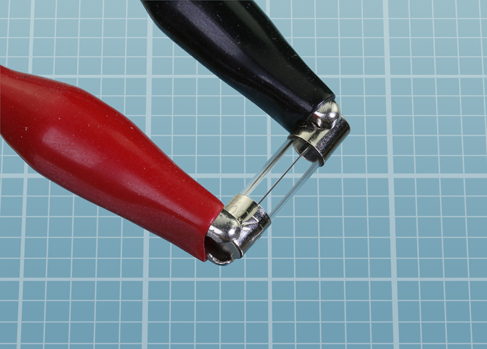
Figure 1-36. How to apply your test leads to a small cartridge fuse.
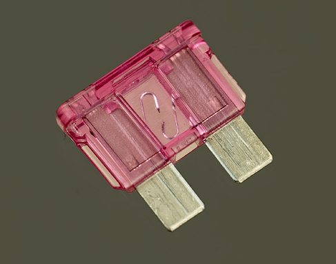
Figure 1-37. Note the break in the element.

Figure 1-38. In a shorted cartridge fuse, a similar break appears.
This is how a fuse works: it melts to protect the rest of the circuit. That tiny break inside the fuse stops any more current from flowing.
Fundamentals: Direct and Alternating Current
The flow of current that you get from a battery is known as direct current, or DC. Like the flow of water from a faucet, it is a steady stream that flows in one direction.
The flow of current that you get from the power outlet in your home is very different. The “live” side of the outlet changes from positive to negative, relative to the “neutral” side, at a rate of 60 times each second (in many foreign countries, including Europe, 50 times per second). This is known as alternating current, or AC, which is more like the pulsing flow you get when you use a power washer to wash a car.
Alternating current is essential for some purposes, such as cranking up voltage so that electricity can be distributed over long distances. AC is also useful in motors and domestic appliances. The parts of a power outlet are shown in Figure 1-39. This style of outlet is found in North America, South America, Japan, and some other nations. European outlets look different, but the principle remains the same.
In the figure, socket A is the “hot” or “live” side of the outlet, supplying voltage that alternates between positive and negative relative to socket B, which is the “neutral” side. If an appliance develops a fault such as an internal loose wire, it should protect you by sinking the voltage through socket C, the ground.

Figure 1-39. The parts of a power outlet.
In the United States, the outlet shown in the diagram is rated for 110 to 120 volts. Other configurations of outlet are used for higher voltages, but they still have live, neutral, and ground wires—with the exception of three-phase outlets, which are used primarily in industry.
For most of this book I’m going to be talking about DC, for two reasons: first, most simple electronic circuits are powered with DC, and second, the way it behaves is much easier to understand.
-
I won’t bother to mention repeatedly that I’m dealing with DC. Just assume that everything is DC unless otherwise noted.
Background: Inventor of the Battery
Alessandro Volta, shown in Figure 1-40, was born in Italy in 1745, long before science was broken up into specialties. After studying chemistry (he discovered methane in 1776) he became a professor of physics and developed an interest in the so-called galvanic response, whereby a frog’s leg will twitch in response to a jolt of static electricity.
Using a wine glass full of salt water, Volta demonstrated that the chemical reaction between two electrodes (one made of copper, the other of zinc) will generate a steady electric current. In 1800, he refined his apparatus by stacking plates of copper and zinc, separated by cardboard soaked in salt and water. This “voltaic pile” was the first electric battery in Western civilization.

Figure 1-40. Alessandro Volta discovered that chemical reactions can create electricity.
Background: Father of Electromagnetism
Born in 1775 in France, André-Marie Ampère (shown in Figure 1-41) was a mathematical prodigy who became a science teacher, despite being largely self-educated in his father’s library. His best-known work was to derive a theory of electromagnetism in 1820, describing the way that an electric current generates a magnetic field. He also built the first instrument to measure the flow of electricity (now known as a galvanometer), and discovered the element fluorine.

Figure 1-41. André-Marie Ampère found that an electric current running through a wire creates a magnetic field around it. He used this principle to make the first reliable measurements of what came to be known as amperage.
Cleanup and Recycling
You can dispose of the battery that you damaged when you shorted it. Putting batteries in the trash is not a great idea, because they contain heavy metals that should be kept out of the ecosystem. Your state or town may include batteries in a local recycling scheme. (California requires that almost all batteries be recycled.) Check your local regulations for details.
The blown fuse is of no further use, and can be thrown away.
The second battery, which was protected by the fuse, should still be OK.
The battery carrier can be reused later.
Experiment 3: Your First Circuit
Now it’s time to make electricity do something more useful. To achieve this, you’ll be experimenting with components known as resistors, and a light-emitting diode, or LED.
What You Will Need
-
9-volt battery (1)
-
Resistors: 470 ohm (1), 1K (1), 2.2K (1)
-
Generic LED (1)
-
Test leads with alligator clips at each end (3)
-
Multimeter (1)
Setup
It’s time to get acquainted with the most fundamental component we’ll be using in electronic circuits: the humble resistor. As its name implies, it resists the flow of electricity. As you might expect, its value is measured in ohms.
If you bought a bargain-basement assortment of resistors, they may be delivered to you in unmarked bags. No problem; we can determine their values easily enough. In fact, even if the packages are clearly labeled, I want you to check the resistors as we go along, because it’s easy to get them mixed up. You have two alternatives:
-
Use your multimeter, after setting it to measure ohms.
-
Learn the color codes that are printed on most resistors. I’ll explain them immediately below.
After you check the values of resistors, it’s a good idea to sort them into labeled compartments in little plastic parts boxes. Personally, I like the boxes sold at the Michael’s chain of crafts stores in the United States, but there are many alternatives. You can also use miniature plastic bags, which you can find by searching eBay for:
plastic bags parts
Fundamentals: Decoding Resistors
Some resistors have a value clearly stated on them in microscopic print that you can read with a magnifying glass, as shown in Figure 1-42.
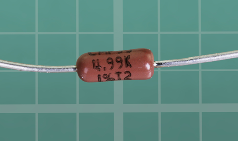
Figure 1-42. Only a minority of resistors have their values printed on them.
However, most resistors are color-coded with stripes. Figure 1-43 shows the coding scheme.
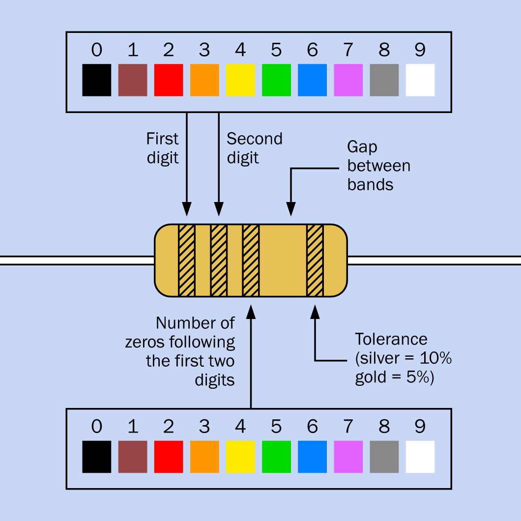
Figure 1-43. The coding scheme that shows the value of a resistor. Some resistors have four stripes on the left instead of three, as explained in the text.
Figure 1-44 shows you some examples. From top to bottom: 1,500,000 ohms (1.5M) at 10% tolerance, 560 ohms at 5%, 4,700 ohms (4.7K) at 10%, and 65,500 ohms (65.5K) at 5%.

Figure 1-44. Four examples of color-coded resistors.
The code can be summarized in words like this:
-
Ignore the color of the body of the resistor. (The exception to this rule would be a white resistor that may be fireproof or fused, and must be replaced with the same type. But you are unlikely to encounter one of these.)
-
Look for a silver or gold stripe. If you find it, turn the resistor so that the stripe is on the righthand side. Silver means that the value of the resistor is accurate within 10%, while gold means that the value is accurate within 5%. This is known as the tolerance of the resistor.
-
If you don’t find a silver or gold stripe, turn the resistor so that the colored stripes are clustered at the left end. Usually there are three of them. If there are four, I’ll deal with those in a moment.
-
The colors of the first two stripes, from left to right, tell you the first two digits in the value of the resistor. The color of the third stripe from the left tells you how many zeros follow the two numbers. The color values are shown in Figure 1-43.
If you run across a resistor with four stripes instead of three, the first three stripes are digits and the fourth stripe is the number of zeros. The third numeric stripe allows a resistor to have an intermediate value.
Confusing? Well, you can still use your meter to check the values. Just be aware that the meter reading may be slightly different from the claimed value of the resistor. This can happen because your meter isn’t absolutely accurate, or because the resistor is not absolutely accurate, or both. Small variations don’t matter in the projects in this book.
Lighting an LED
Now take a look at one of your generic LEDs. Old-fashioned lightbulbs used to waste power by converting a lot of the power into heat. LEDs are much smarter: they convert almost all their power into light, and they last almost indefinitely—provided you treat them right!
An LED is quite fussy about the amount of power it gets, and the way it gets it. Always follow these rules:
-
The longer wire sticking out of the LED must receive a more positive voltage relative to the shorter wire.
-
The positive voltage difference that you apply between the long wire and the short wire must not exceed the limit stated by the manufacturer. This is known as the forward voltage.
-
The current passing into the LED through the long wire and out through the short wire must not exceed the limit stated by the manufacturer. This is known as the forward current.
What happens if you break these rules? You’ll see for yourself in Experiment 4.
Make sure you have a fresh 9-volt battery. You could use a connector with the battery, as shown in Figure 1-8, but I think it’s easier just to clip a couple of test leads directly to the battery terminals, as in Figure 1-45.
Select a 2.2K resistor. Remember, 2.2K means 2,200 ohms. Why is it 2,200 and not a nice round amount such as 2,000? I’ll explain that shortly. See “Background: Puzzling Numbers” if you want to know right now.
The colored stripes on your 2.2K resistor should be red-red-red, meaning 2 followed by another 2 and two more zeros. You will also need a 1K resistor (brown-black-red) and a 470-ohm resistor (yellow-violet-brown), so have them ready.
Wire the 2.2K resistor into the circuit shown in Figure 1-45. Make sure you get the battery the right way around, with its positive terminal on the right.
-
The “plus” symbol always means “positive.”
-
The “minus” symbol always means “negative.”
Be sure that the long lead of the LED is on the right, and be careful that none of the alligator clips touches each other. You should see the LED glow dimly.
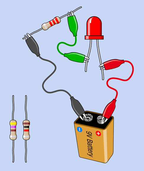
Figure 1-45. Your first circuit, to light an LED.
Now swap out your 2.2K resistor and substitute the 1K resistor. The LED should glow more brightly.
Swap out the 1K resistor and substitute a 470-ohm resistor, and the LED should be brighter still.
This may seem obvious, but it makes an important point. The resistor blocks a percentage of the current in the circuit. A higher-value resistor blocks more current, leaving less for the LED.
Checking a Resistor
I mentioned that you can use your meter to check the value of a resistor. This is really very easy. The procedure is shown in Figure 1-46. First, don’t forget to set your meter to ohms. Disconnect the resistor from any other components, and apply the probes of your meter. If you have a manual-ranging meter, you must set the meter to a higher value than you expect to find. Otherwise, you’ll get an error message.
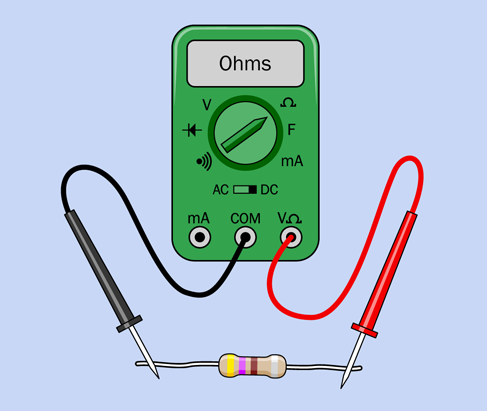
Figure 1-46. Testing the value of a resistor.
One thing to bear in mind is that you will get a more accurate reading if you press the probes firmly against the leads of the resistor. Don’t hold the resistors and probes between your fingers—you don’t want to measure the resistance of your body along with the resistance of the resistor. Place the resistor on an insulating surface, such as a nonmetallic desktop. Hold the probes by their plastic handles, and press down hard with the metal tips.
Alternatively, you can use a couple of test leads. Clip one end of each lead to each end of the resistor, and clip the other ends of the leads to the meter probes. Now you can do hands-free resistor testing, which is much easier.
Background: Puzzling Numbers
After you check a few resistors (or shop for them online) you’ll notice that the same pairs of digits keep recurring. In thousands of ohms, we often find 1.0K, 1.5K, 2.2K, 3.3K, 4.7K, and 6.8K. In tens of thousands, we find 10K, 15K, 22K, 33K, 47K, and 68K.
The pairs of digits are known as multipliers, because you can multiply them by 1, or 1,000, or 10,000, or 100, or 10 to get basic resistor values in ohms.
There is a logical reason for this. Long ago, many resistors had an accuracy of plus-or-minus 20%, and therefore a 1.0K resistor could have an actual resistance as high as 1 + 20% = 1.2K while a 1.5K resistor could have a resistance as low as 1.5 – 20% = 1.2K. Therefore, it was pointless to have any values between 1K and 1.5K. Similarly, a 68 ohm resistor could have a value as high as 68 + 20% = just over 80 ohms, while a 100 ohm resistor could have a value as low as 100 – 20% = 80 ohms; so, it was unnecessary to have a value between 68 and 100.
In the top row of the table in Figure 1-47, the white numbers were the original multipliers for resistors. These numbers are still the most widely used today, even though modern resistor values are plus-or-minus 10% or better.
If you include the numbers in black type with the numbers in white type, you get all the possible multipliers for 10% resistors. If you then include the values in blue type, you have all the possible multipliers for 5% resistors.

Figure 1-47. Traditional multipliers for resistor and capacitor values. See text for details.
I have only used the original six multipliers for the projects in this book, to minimize the range of resistors that you will require. If accuracy is important (in Experiment 19, for example, where a circuit measures the speed of your reflexes) you can use a potentiometer to fine-tune the output—as I will show you in the very next experiment.
Cleanup and Recycling
You’ll use the battery and the LED in the next experiment. The resistors can be reused in the future.
Experiment 4: Variable Resistance
You can vary the resistance in a circuit by inserting a potentiometer, which will control the current. The potentiometer in this experiment will enable you to learn more about voltage, amperage, and the relationship between them. You’ll also learn how to read a manufacturer’s datasheet.
What You Will Need
-
9-volt battery (1)
-
Resistors: 470 ohms (1) and 1K (1)
-
Generic LEDs (2)
-
Test leads with alligator clips at each end (4)
-
Potentiometer, 1K linear (2)
-
Multimeter (1)
Look Inside Your Potentiometer
The first thing I want you to do is see for yourself how a potentiometer works, and the best way to accomplish this is to open it. This is why I asked you to acquire two potentiometers for this experiment—in case you can’t put the first one back together again.
Some readers of the first edition of this book complained that it’s wasteful to risk destroying a potentiometer by prying it open. But almost any learning experience consumes some resources, from pens and paper to whiteboard markers. If you really don’t want to risk the future of your potentiometer, you can leave it untouched while you study the photographs that follow.
Most potentiometers are held together with little metal tabs. You need to bend the tabs upward. One way to do this is to slide in a knife and use it as a lever. Another way is to use a screwdriver—or maybe some pliers. I haven’t specified any tools for this experiment, because I am hoping you already have a knife, or a screwdriver, or pliers in your home.
Figure 1-48 shows the tabs circled in red. (A fourth one is hidden behind the shaft of the component.) Figure 1-49 shows the tabs bent upward and outward.

Figure 1-48. The tabs that hold a potentiometer together.
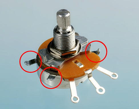
Figure 1-49. The tabs have been bent upward and outward.
After you have pried up the tabs, very carefully pull up on the shaft while holding the body of the potentiometer in your other hand. It should come apart as shown in Figure 1-50.

Figure 1-50. The wiper of the potentiometer is circled.
Inside the shell you will find a circular track. Depending on whether you have a really cheap potentiometer or a slightly more high-class version, the track will be made of conductive plastic or will have thin wire wrapped around it, as shown in the photograph. Either way, the principle is the same. The wire or the plastic possesses some resistance (a total of 1,000 ohms in a 1K potentiometer), and as you turn the shaft, a wiper rubs against the resistance, giving you a shortcut to any point from the center terminal. The wiper is circled red in Figure 1-50.
You can probably put it back together, but if necessary, use your backup potentiometer.
Testing the Potentiometer
Set your meter to measure resistance (at least 1K, on a manual-ranging meter) and touch the probes to the two adjacent terminals shown in Figure 1-51. You should find that when you turn the shaft of the potentiometer clockwise (seen from above), the resistance diminishes to almost zero. When you turn the shaft counterclockwise, the resistance increases to about 1K. Now keep the black probe where it is, and touch the red probe on the opposite terminal. The behavior of the potentiometer will be reversed.
Do you think, maybe, the middle terminal connects with the wiper inside the potentiometer? Do you think the other two terminals connect with the ends of the track?
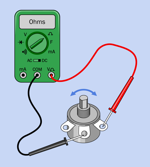
Figure 1-51. Procedure for testing the behavior of a potentiometer.
If you move the red probe to where the black probe is, and move the black probe to where the red probe was, the resistance between them will not change. It’s the same in both directions. Unlike an LED, which has to be connected the right way around, a potentiometer has no polarity.
Caution: Don’t Add Power
Don’t apply power to a circuit while trying to measure resistance. Your meter uses a small amount of voltage from its internal battery when you are measuring resistance. You don’t want that voltage to fight with voltage that you are applying from a battery.
Caution: Destructive Experiment Ahead
I have performed the next procedure many times uneventfully, but one reader reports that his LED fractured. You may wish to use safety glasses, if you want to be cautious. Regular eyeglasses will be acceptable.
Dimming Your LED
Now you can use the potentiometer to control the brightness of your LED. Connect everything exactly as shown in Figure 1-52. Make sure the two alligator clips are on the terminals shown. You are now using a variable resistance (the potentiometer) where the fixed resistor was in Experiment 3 (see Figure 1-45).
Begin with the shaft turned all the way counterclockwise (seen from above), otherwise you’ll burn out the LED before we even get started. Now turn the shaft clockwise, very slowly, as shown by the blue arrow. You’ll notice the LED glowing brighter, and brighter, and brighter—until, oops, it just went dark! You see how easy it is to destroy modern electronics? When I titled this procedure “Dimming your LED,” you probably didn’t realize I was talking about dimming it permanently.
Set aside that LED. I’m sorry to say, it will never glow again.

Figure 1-52. Adjusting the brightness of an LED with a potentiometer.
Substitute a new LED, and this time, let’s protect it. Add a 470-ohm resistor, as shown in Figure 1-53. Electricity now passes through the 470-ohm resistor as well as the potentiometer, so that the LED will be protected even if the potentiometer’s resistance diminishes to zero. You can turn the shaft of the potentiometer without worrying about destroying anything.

Figure 1-53. Protecting the LED.
The lesson that I hope you have learned is that an LED is too sensitive to be connected directly with a 9-volt battery. It must always be protected by some extra resistance in the circuit.
Could you power an LED directly from a single 1.5-volt battery? Try it. You may get a dim glow, but 1.5 volts is below the threshold for the LED. Let’s find out how much voltage an LED needs.
Measuring Potential Difference
While the battery is connected in the circuit, set the dial of your meter to measure volts DC. You can leave the red lead plugged into the meter where it was before, because the socket for measuring volts is the same as the socket for measuring ohms.
If your meter uses manual ranging, set the voltage higher than 9 volts. Remember, the numbers beside the dial on the meter are the maximum in each range.
Now touch the probes to the terminals of the potentiometer that you are using, as shown in Figure 1-54. Try to hold the probes in place while you turn the potentiometer up a little, and down a little. You should see the voltage changing accordingly. We call this the potential difference between the two probes.
-
“Potential difference” means the same as voltage between two points.
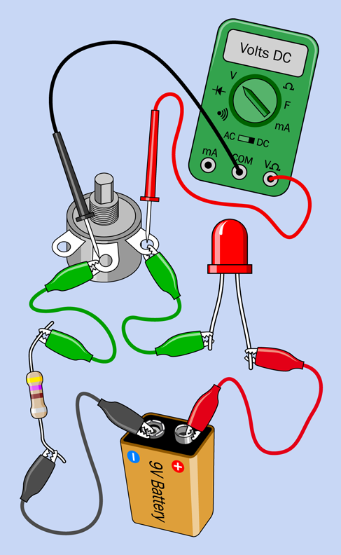
Figure 1-54. Measuring the potential difference across the potentiometer.
If you measure the potential across the LED, this will also change when you adjust the potentiometer, although not as much as you might expect. An LED self-adjusts to some extent, modifying its resistance as the voltage and current fluctuate.
What if you swap the positions of the red and black probes? A minus sign should appear in the meter’s display. You won’t damage the meter this way, but it’s less confusing if you always measure voltage with the red probe more positive than the black probe.
Lastly, touch the probes across the fixed-value resistor, and once again the potential difference will change when you adjust the potentiometer. Voltage from the battery is shared by all the components in this simple circuit. When the potentiometer reduces its share, a larger voltage difference is available for the fixed-value resistor and the LED. In addition, when the potentiometer has a lower resistance, the total resistance in the circuit is lower, allowing more current to flow.
A few things to keep in mind:
-
If you add up the potential differences across all the devices in the circuit, the total will be the same as the voltage supplied by the battery.
-
You measure voltage relatively between two points in a circuit. This is what their potential difference means.
-
When measuring voltage, apply your meter like a stethoscope, without disturbing or breaking the connections in the circuit.
Checking the Flow
Now I want you to make a different measurement. I want you to check the amperage in the circuit, using your meter set to mA (milliamps). When measuring current, you must observe these rules:
-
You can only measure current (amperage) when it passes through the meter.
-
You have to insert your meter into the circuit.
-
Too much current will blow the fuse inside your meter.
-
You will have to use a socket on the meter labelled mA. This may be the same as the socket that you have used so far, or it may be different.
Make sure you turn the dial on your meter to measure mA, not volts, before you try this.
Caution: Meter Overload
Be careful when measuring current. For instance, if you put the probes of your meter directly against the terminals of a battery, and the meter is set to measure mA, you will create an instant overload, and the meter will blow its internal fuse. A cheap meter will not have any fuses supplied with it, so you’ll have to open the case, check the value of the fuse, and search around online until you find an exact replacement. This is really annoying (I have been through it myself, more than once). A really cheap meter may not even have an easily replacable fuse.
-
Always measure current when there are components in the circuit to restrict the flow.
-
As a precaution, if your meter has a separate socket for measuring current, plug the red lead into that socket only while you are actually performing that task. Move the red lead back to the volts/ohms socket afterward.
Checking the Current
Insert the meter between the LED and the potentiometer, as shown in Figure 1-55. As you adjust the potentiometer up and down a little, you should find that the varying resistance in the circuit changes the flow of current—the amperage. The LED burned out in the previous experiment because too much current made it hot, and the heat melted it inside, just like a fuse. A higher resistance limits the amperage.
Now here’s an interesting test. Turn the potentiometer all the way counterclockwise. Make a note of the current that you measure.

Figure 1-55. Current passes through the meter on its way around the circuit.
Without readjusting the potentiometer, move the meter and insert it between the battery and the LED, as shown in Figure 1-56. What’s the value of the current now? It should be exactly the same as before—or very nearly the same, allowing for tiny changes in resistance that resulted from shifting the alligator clips.
-
The current is the same at all points in a simple circuit. It has to be, because the flow of electrons has no place else to go.
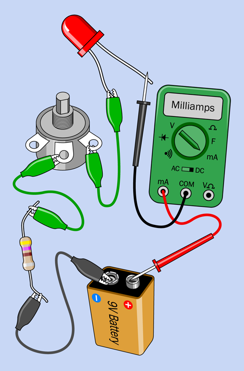
Figure 1-56. The current flowing through a simple circuit is always the same throughout the circuit, regardless of where you measure it.
Making Measurements
It’s time now to nail this down with some numbers. This will enable you to establish the most fundamental rule in all of electronics.
Remove the LED from the circuit, and put the meter directly between the battery and the potentiometer. Remove the 470-ohm resistor, and substitute a 1K resistor (with colors brown-black-red), as shown in Figure 1-57. Now the only resistance in the circuit is provided by the 1K potentiometer plus the 1K resistor. (Your meter also has some resistance, but it’s so low, we can ignore it. The wires and alligator clips also have some tiny amount of resistance, but this is even lower than the resistance of the meter.)
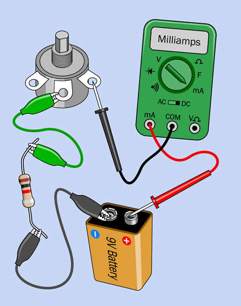
Figure 1-57. In this final LED test, you get rid of the LED.
Turn the potentiometer all the way clockwise, so that it provides almost-zero resistance. You now have only 1,000 ohms in the circuit, from the resistor. How much current does your meter show flowing?
Turn the potentiometer halfway, so it creates about 500 ohms resistance. The total resistance in the circuit is now 1,500 ohms, approximately. How much current does your meter show, now?
Turn the potentiometer all the way counterclockwise, so its full value is in the circuit, plus the resistor, making 2,000 ohms total. What’s the amperage now?
When I tried this, I got the values shown below. Yours should be about the same.
9mA with 1K total resistance
6mA with 1.5K total resistance
4.5mA with 2K total resistance
Do you notice something interesting? On each line, if you multiply the number on the left by the number on the right, the result is always 9. And 9 volts just happens to be the voltage of the battery.
We only have three measurements, but if you ran a more detailed test using a series of resistors with fixed values, I’ll bet that the result would be the same. I can summarize it like this:
battery voltage = milliamps × kilohms
But wait a minute: 1K is 1,000 ohms, and 1mA is 1/1,000 of an amp. Therefore, using the fundamental units of volts, amps, and ohms, our formula should really look like this:
voltage = (amps / 1,000) × (ohms × 1,000)
(I’m using the / symbol, which is often referred to as the “slash” symbol, to mean “divide by.”)
The two factors of 1,000 cancel each other out, so we get this:
volts = amps × ohms
Fundamentals: Ohm’s Law
The general way to express Ohm’s Law is:
voltage = current × resistance
which is usually abbreviated like this:
V = I × R
Letter I represents the flow of current, because originally current was measured by its inductance, meaning the ability to induce magnetic effects. Perhaps it would be more helpful if some other letter, such as C, was used to represent current, but it’s too late to persuade everyone to do that. You just have to remember that I means current.
By shifting the terms around, you get these versions of the formula:
I = V / R
R = V / I
To apply the formula, you have to make sure that the units are consistent. If V is measured in volts, and I is measured in amps, then R must be measured in ohms.
What if you have measured a current in milliamps? You must express it in amps. For instance, a current of 30mA must be written as 0.03 in the formula, because 0.03A = 30mA. If you get confused, use a calculator to divide milliamps by 1,000 to get a value in amps. Likewise, divide millivolts by 1,000 to get a value in volts.
To minimize the risk of errors, you can memorize Ohm’s Law using the actual units, like this:
volts = amps × ohms
amps = volts / ohms
ohms = volts / amps
But remember:
Fundamentals: Series and Parallel
In your test circuit, the resistor and the potentiometer have been connected in series, meaning that the electricity had to go through one before it went through the other. The alternative would have been to put them side by side, in parallel.
-
Resistors in series are positioned so that one follows the other.
When you put two equal-valued resistors in series, you double the total resistance, because electricity has to pass through two barriers in succession. This is shown in Figure 1-58.
When you put two equal-valued resistors in parallel, you cut the total resistance in half, because you’re giving the electricity two paths of equal resistance instead of one. This is shown in Figure 1-59.
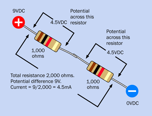
Figure 1-58. Two resistors of the same value in series.
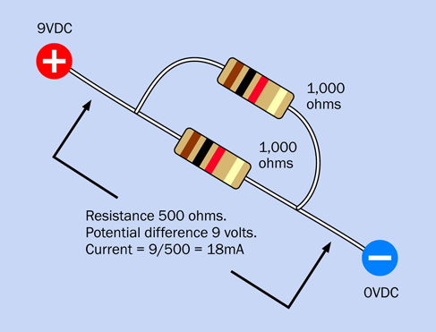
Figure 1-59. Two resistors of the same value in parallel.
In both figures, the current in milliamps has been calculated using Ohm’s Law.
In reality we don’t normally need to put resistors in parallel, but we often put other types of components in parallel. All the lightbulbs in your house, for instance, are wired in parallel across the main supply. So, it’s useful to understand that resistance in a circuit goes down if you keep adding components in parallel. At the same time, as you add more pathways for electricity to follow, the total current through the circuit goes up.
Using Ohm’s Law
Ohm’s Law is extremely useful. For example, it can tell you precisely what resistance to put in series with an LED, to protect it adequately while generating as much light as possible.
The first step is to discover the specification for the LED established by its manufacturer. This information is easily available in a datasheet that you can locate online. Suppose you have an LED made by Vishay Semiconductors. You know that its part number is TLHR5400, because the number was printed on a label when you received a bag of LEDs in the mail, and you snipped out the label and stored it with the LEDs. (At least, that’s what you should have done.)
All you have to do is Google the part number and the manufacturer’s name:
vishay tlhr5400
The very first hit is the datasheet maintained by Vishay. Scroll down, and you see the information that you need. I’ve included the left side and right side of a screen capture in Figure 1-60. I outlined the part number of the component in red on the left, and I outlined two types of forward voltage on the right. “Typ” means typical and “Max,” as I’m sure you guessed, is maximum. So, the LED typically should run with a 2V potential difference. But what does “at IF (mA)” mean? Well, remember that the letter I is used to represent the current passing through a circuit. The letter F means “Forward.” So the forward voltage in the table is measured at a forward current of 20mA, which is the recommended value for this LED.
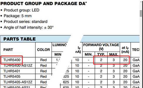
Figure 1-60. Screen capture from an LED datasheet.
How about if you have a Kingbright WP7113SGC? This time, the second hit from a Google search takes you to the appropriate datasheet, where the second page specifies a typical forward voltage of 2.2V, maximum 2.5V, and a maximum forward current of 25mA. The layout of the Kingbright datasheet is different from that of the Vishay datasheet, but the information is still easy to find.
Let’s go with the Vishay LED. Now that you know that it works well with 2V and 20mA, Ohm’s Law can tell you the rest.
How Big a Resistor?
In the simple circuit shown in Figure 1-61, you want to know the correct value for the resistor. Begin by recalling the rule I mentioned before:
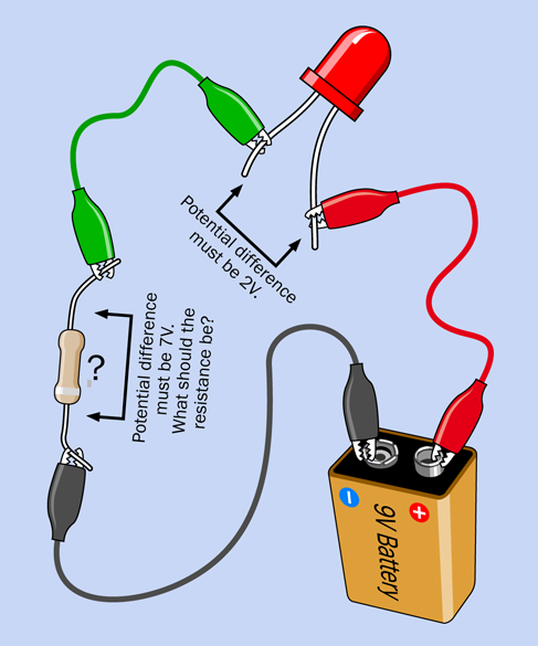
Figure 1-61. This basic circuit enables you to calculate the value of the resistor.
-
If you add up the potential differences across all the devices in the circuit, the total will be the same as the voltage supplied by the battery.
The battery is 9V, of which we want the LED to take 2V. Therefore, the resistor must drop the voltage by 7V. What about the current? Remember another rule that I mentioned previously:
-
The current in a simple circuit is the same at all locations in the circuit.
Therefore, the current through the resistor will be the same as the current through the LED. Your target is 20mA, but Ohm’s Law requires you to make all the units match. If you are dealing with volts and ohms, you have to express the current in amps. Well, 20mA is 20 / 1,000 amps, which is 0.02 amps.
Now you can write down what you know, which is always the first step:
V = 7
I = 0.02
Which version of the Ohm’s Law formula should you use? The one where the value that you don’t know, and want to know, is on the left. That would be this one:
R = V / I
Now plug the values for V and I into the formula, like this:
R = 7 / 0.02
There’s a trick that I will tell you for doing calculations involving decimal points, but to save time, use your calculator to show you the answer:
7 / 0.02 = 350 ohms
That is not a standard value for resistors, but 330 ohms is. Alternatively, just in case you use a more sensitive LED, you could move up to the next higher standard resistance value, which is 470 ohms. You may remember, I used a 470-ohm resistor in Experiment 3. Now you know why: I did the math.
Some people make the mistake of thinking that when they divide volts by amps to find the correct value for a series resistor, they should use the supply voltage (9V in this case). This is not correct, because the supply voltage is being applied to the resistor and the LED. To find the value for the resistor, you have to consider just the potential difference across it alone, which is 7V.
What happens if you use a different power supply? Later in the book, you’ll be using a 5V supply in several experiments. How will this change the appropriate value of the resistor?
The LED still has to take 2V. The power supply is 5V, so the resistor has to drop 3V. The current should still be the same, and the calculation now looks like this:
R = 3 / 0.02
Therefore the resistance value is 150 ohms. But you don’t need the LED to deliver its maximum light output, and you might happen to use an LED that has a lower limit than 20mA. Also, if a battery is powering the circuit, you might want to reduce the power consumption to make the battery last longer. Bearing this in mind, you could use the next higher standard value for the resistor, which would be 220 ohms.
Background: Hot Wires
I mentioned that wires have a very low resistance. Is it so low that you can always ignore it? Actually, no. If a large current is flowing through a wire, the wire will get hot, as you saw yourself when the 1.5-volt battery was shorted out in Experiment 2. And if the wire gets hot, you can be sure that some voltage is being blocked by the wire, leaving less voltage available for any device attached to the wire.
Once again, you can use Ohm’s Law to establish some numbers.
Suppose that a very long piece of wire has a resistance of 0.2 ohms. You want to run 15 amps through it, to run a device that consumes a lot of power.
You begin by writing down what you know:
R = 0.2 (resistance of the wire)
I = 15 (amperage through the circuit)
You want to know V, the voltage drop between one end of the wire and the other. So you should use the version of Ohm’s Law that places V on the left side:
V = I × R
Now plug in the values:
V = 15 × 0.2 = 3 volts
Three volts is not a big deal if you have a high-voltage power supply, but if you are using a 12-volt car battery, this length of wire will take one-quarter of the available voltage.
Now you know why the wiring in automobiles is relatively thick—to waste as little of the 12V power as possible.
Fundamentals: Decimals
Legendary British politician Sir Winston Churchill is famous for complaining about “those damned dots.” He was referring to decimal points. Because Churchill was Chancellor of the Exchequer at the time, supervising all government expenditures, his difficulty with decimals was a bit of a problem. Still, he muddled through in time-honored British fashion, and so can you.
Suppose you have decimals in a division sum. You can make it easier by moving the decimal points in the top half and the bottom half of the division by the same number of places. So, when you wanted to know the answer to 7 / 0.02 to find the series resistor for the LED, you could move the decimals two spaces to the right:
7 / 0.02 = 700 / 2
This is much easier. Notice that if you move a decimal point to the right beyond a digit, you add a zero for each extra place. So, when you move the decimal in 7.0 two places to the right, you get 700.
What if you have decimals in a multiplication sum? For example, you need to multiply 0.03 by 0.002. Because you are now multiplying instead of dividing, you have to move the decimal points in opposite directions. Like this:
0.03 × 0.002 = 3 × 0.00002
So the answer is 0.00006. Again, if you find this too confusing, you can use a calculator. But sometimes it’s quicker to use a pen and paper—or even do it in your head.
Theory: The Math on Your Tongue
I’m going back to the question I asked in the previous experiment: why didn’t your tongue get hot?
Now that you know Ohm’s Law, you can figure out the answer in numbers. Let’s suppose the battery delivered its rated 9 volts, and your tongue had a resistance of 50K, which is 50,000 ohms. As always, begin by writing down what you know:
V = 9
R = 50,000
You want to know the current, I, so you use the version of Ohm’s Law that puts this on the left:
I = V / R
Plug in the numbers:
I = 9 / 50,000 = 0.00018 amps
Move the decimal point three places to convert from amps to milliamps:
I = 0.18 mA
That’s a very small current. It will not produce much heat.
What about when you shorted out the battery? How much current made the wires get hot? Well, suppose the wires had a resistance of 0.1 ohms (probably it’s less, but I’ll start with 0.1 as a guess). Write down what you know:
V = 1.5
R = 0.1
Once again I’m trying to find I, the current, so I use:
I = V / R
Plug in the numbers:
I = 1.5 / 0.1 = 15 amps
That’s almost 100,000 times the current that may have passed through your tongue. It generated substantial heat in a thin wire.
A room heater or a large power tool, such as a table saw, might draw 15 amps. Maybe you’re wondering if that little AA battery really could deliver as much current as that. The answer is . . . I’m not sure. I couldn’t measure the current with my meter, because 15A would blow the meter’s fuse, even if I plug the probe into the high-current socket labeled 10A. But I did try the experiment with a 10-amp fuse instead of a 1-amp fuse, and the 10-amp fuse survived.
Now, why was that? Ohm’s Law says that the current should be 15A, but for some reason it was less. Maybe the resistance of the wire on the battery carrier was actually higher than 0.1 ohms? No, I think it was probably lower. So—what was restricting the current to a lower value than Ohm’s Law predicted?
The answer is that everything in the everyday world has some electrical resistance, even including a battery. Always remember that a battery is an active part of a circuit.
Do you remember that when you shorted out the battery, it became hot, as well as the wires? Definitely, the battery has some internal resistance. You can ignore it when you are dealing with small currents in milliamps, but for large currents, the battery is actively involved.
This is why I cautioned against using a larger battery (especially a car battery). Larger batteries have a much lower internal resistance, allowing much higher currents, which can generate explosive amounts of heat. A car battery is designed to deliver literally hundreds of amps when it turns a starter motor. That’s quite enough current to melt wires and cause nasty burns. In fact, you can weld metal using a car battery.
Lithium batteries also have low internal resistance, making them very dangerous when they’re shorted out. Here’s the take-home message:
-
High current is not dangerous in the same way as high voltage. But it is still dangerous.
Background: The Watt
So far I haven’t mentioned a unit that everyone is familiar with: watts.
A watt is a unit of power, and when power is applied throughout a period of time, it performs work. An engineer might say that work is done when a person, an animal, or a machine pushes something to overcome mechanical resistance. Examples would be a car cruising along a level stretch of road (overcoming friction and air resistance) or a person walking upstairs (overcoming the force of gravity).
When one watt of power is applied for one second, the work done is one joule, usually represented by letter J. If P is used to represent power:
J = P × s
Or if the formula is turned around:
P = J / s
When electrons push their way through a circuit, they are overcoming a kind of resistance, and so they are doing work.
The electrical definition of a watt is easy:
watts = volts × amps
Or, using the units customarily assigned, with W meaning watts, these three formulas all mean the same thing:
W = V × I (watts = volts × amps)
V = W / I
I = W / V
The terms milliwatts (mW), kilowatts (kW), and megawatts (MW) are commonly used in different situations—megawatts being usually reserved for heavy-duty equipment such as generators in power stations. Be careful not to confuse the lowercase m in the abbreviation for milliwatts with the uppercase M in the abbreviation for megawatts. A conversion table for milliwatts, watts, and kilowatts is shown in Figure 1-62.

Figure 1-62. Conversion table for the most common multiples of watts.
Old-style incandescent light bulbs are calibrated in watts. So are stereo systems. The watt is named after James Watt, inventor of the steam engine. Incidentally, watts can be converted to horsepower, and vice versa.
Resistors are commonly rated as being capable of dealing with 1/4 watt, 1/2 watt, 1 watt, and up. For all of the projects in this book, you can use 1/4-watt resistors. How do I know this?
Go back to the first LED circuit, using a 9V battery. Remember you wanted the resistor to drop the voltage by 7 volts, at a current of 20mA. How many watts of power would the resistor have to deal with?
Write down what you know:
V = 7 (potential difference at the resistor)
I = 20mA = 0.02 amps
You want to know W, so use this version of the formula:
W = V × I
Plug in the numbers:
W = 7 × 0.02 = 0.14 watts
This is the power being dissipated by the resistor.
Because 1/4 watt is 0.25 watts, a 1/4 watt resistor will have no trouble dealing with 0.14 watts. In fact you could almost use a 1/8 watt resistor, but in future experiments we may need resistors that can handle 1/4 watt, and there’s no penalty for using a resistor that is rated for more watts than necessary. They just cost slightly more and are slightly larger.
Background: The Origins of Wattage
James Watt, shown in Figure 1-63, is known as the inventor of the steam engine. Born in 1736 in Scotland, he set up a small workshop in the University of Glasgow, where he struggled to perfect an efficient design for using steam to move a piston in a cylinder. Financial problems and the primitive state of the art of metal working delayed practical applications until 1776.

Figure 1-63. James Watt’s development of steam power enabled the industrial revolution. After his death, he was honored by having his name applied to the basic unit of power in electricity.
Despite difficulties in obtaining patents (which could only be granted by an Act of Parliament in those times), Watt and his business partner eventually made a lot of money from his innovations. Although he predated the pioneers in electricity, in 1889 (70 years after his death) his name was assigned to the basic unit of electric power that can be defined by multiplying amperes by volts.
Cleanup and Recycling
The dead LED can be thrown away. Everything else is reusable.
Experiment 5: Let’s Make a Battery
Long ago, before the Web existed, kids were so horribly deprived, they tried to amuse themselves with kitchen-table experiments such as making a battery by pushing a nail and a penny into a lemon. Hard to believe, but true!
Now that modern LEDs will emit light when just a few milliamps flow through them, the old lemon-battery experiment is more interesting. If you’ve never tried it, the time is right.
What You Will Need
-
Lemons (2) or squeeze-bottle of pure lemon juice (1)
-
Copper-plated coins, such as US pennies (4)
-
One-inch (or larger) zinc-plated steel brackets from a hardware store (4)
-
Test leads with alligator clips at each end (5)
-
Multimeter (1)
-
Low-current LED (1). (See “Light-Emitting Diodes” for a reminder of the difference between generic and low-current LEDs)
Setup
A battery is an electrochemical device, meaning that chemical reactions create electricity. Naturally, this only works if you have the right chemicals working for you, and the ones I’m going to use are copper, zinc, and lemon juice.
The juice should be no problem. Lemons are cheap, or you can buy one of those little yellow plastic squeeze-bottles of concentrated juice. Either will work.
Pennies are not made of copper anymore, but they are still plated with a thin layer of copper, which is good enough. Just make sure that your pennies are new and bright. If the copper has oxidized, it will be a dull brown, and the experiment won’t work as well.
Zinc is a bit more of a problem. What you need is a metal part that is galvanized, meaning it is coated in zinc to prevent rust. Small galvanized steel brackets should be available at your local hardware store, and they don’t cost much. Brackets that measure about one inch along each side will be fine.
Lemon Test: Part One
Cut a lemon in half, and push a penny into it. As close as possible to the penny (but not touching it), push in your galvanized bracket. Now set your multimeter so that it can measure up to 2V DC, and hold one probe against the penny while you hold the other probe against the bracket. You should find that your meter detects between 0.8V and 1V.
To power a typical LED, you need more voltage. How can you get it? By putting batteries in series. In other words, more lemons! You’ll use test leads to link the batteries, as shown in Figure 1-64. Notice that each lead connects a bracket to a penny. Do not connect pennies to pennies or brackets to brackets.
If you set things up carefully, keeping the pennies and brackets close to each other but making sure they don’t actually touch each other, you should be able to illuminate your LED with three lemon-juice batteries in series.
Another option is to use a little parts box divided into small sections, as shown in Figure 1-65. When everything is nicely aligned, squeeze in some concentrated lemon juice. Vinegar or grapefruit juice may also work.

Figure 1-64. A three-lemon battery should generate just enough voltage to drive a low-current LED.
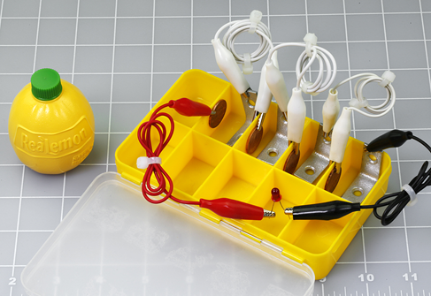
Figure 1-65. Lemon juice, either from lemons or from a squeeze-bottle, will produce reliable results, even though the equipment doesn’t look so nice. Here a box intended for parts has been repurposed as a four-cell juice battery.
I decided to have four cells in my juice battery, because the LED pulls the voltage down somewhat, and the battery is not capable of delivering enough current to damage the LED. The setup in the photograph worked immediately.
Theory: The Nature of Electricity
To understand why the lemon battery works, you have to start with some basic information about atoms. Each atom consists of a nucleus at the center, containing particles called protons, which have a positive charge. The nucleus is surrounded by electrons, which carry a negative charge.
Breaking up the nucleus of an atom requires a lot of energy, and can also liberate a lot of energy—as happens in a nuclear explosion. But persuading a couple of electrons to leave an atom (or join an atom) can take very little energy. For instance, when zinc reacts chemically with an acid, this can liberate electrons.
The reaction soon stops if the zinc-plated part isn’t connected with anything, as electrons accumulate with nowhere to go. They have a mutual force of repulsion, and you can imagine them like a crowd of hostile people, each one wanting the others to leave, and refusing to allow new ones to join them, as shown in Figure 1-66.

Figure 1-66. Electrons on an electrode have a bad attitude known as mutual repulsion.
Now consider what happens when a wire connects the zinc electrode, which has a surplus of electrons, to another electrode, made from a different material (such as copper), which contains “holes” for the electrons to occupy. The electrons can pass through the wire very easily by jumping from one atom to the next. As soon as we open up this pathway, mutual repulsion makes the electrons try to escape from each other to their new home as quickly as possible. This is how an electric current is created. See Figure 1-67.

Figure 1-67. Electrons escaping from a zinc electrode to a copper electrode.
Now that the population of electrons on the zinc electrode has been reduced, the zinc–acid reaction can continue, replacing the missing electrons with new ones—which promptly imitate their predecessors and try to get away from each other by running away down the wire. They move with such force, we can divert them through an LED, and they will liberate some of their energy by making it light up.
The process continues until the zinc–acid reaction grinds to a halt, usually because it creates a layer of a compound such as zinc oxide, which won’t react with acid and prevents the acid from reacting with the zinc underneath. (This is why your zinc electrode may have looked sooty when you pulled it out of the acidic electrolyte.)
This description applies to a primary battery, meaning one that is ready to generate electricity as soon as a connection between its terminals allows electrons to transfer from one electrode to the other. The amount of current that a primary battery can generate is determined by the speed at which chemical reactions inside the battery can liberate electrons. When the raw metal in the electrodes has all been used up in chemical reactions, the battery can’t generate any more electricity and is dead. It cannot easily be recharged, because the chemical reactions are not easily reversible, and the electrodes may have oxidized.
In a rechargeable battery, also known as a secondary battery, a smarter choice of electrodes and electrolyte does allow the chemical reactions to be reversed.
Background: Positive and Negative
I’ve told you that electricity is a flow of electrons, which have a negative charge. In that case, why have I been talking as if electricity flows from the positive terminal to the negative terminal of a battery, in the experiments that you have performed so far?
The story started with an embarrassment in the history of research into electricity. When Benjamin Franklin was trying to understand the nature of electric current by studying phenomena such as lightning during thunderstorms, he believed he observed a flow of “electrical fluid” from positive to negative. He proposed this concept in 1747.
In fact, Franklin had made an unfortunate error that remained uncorrected until physicist J. J. Thomson announced his discovery of the electron in 1897. Electricity really is a flow of negatively charged particles, from an area of greater negative charge to some other location that is “less negative” or “more positive.” In a battery, electrons originate from the negative terminal and flow to the positive terminal.
You might think that when this fact was established, everyone should have discarded Ben Franklin’s idea of a flow from positive to negative. But people had been thinking in those terms for 150 years. Also, when an electron moves through a wire, you can think of an equal positive charge flowing in the opposite direction. When the electron leaves home, it takes a small negative charge with it; therefore, its home becomes a bit more positive. When the electron arrives at its destination, its negative charge makes the destination a bit less positive. This is pretty much what would happen if an imaginary positive particle traveled in the opposite direction. Moreover, all of the mathematics describing electrical behavior are still valid if you apply them to the imaginary flow of positive charges.
As a matter of tradition and convenience, Ben Franklin’s erroneous concept of flow from positive to negative survived, because in the end, it makes no difference.

Figure 1-68. In some weather conditions, the flow of electrons during a lightning strike can be from the ground, through your feet, out of the top of your head, and up to the clouds. Benjamin Franklin would have been surprised.
In the symbols that represent components such as diodes and transistors, you will find arrows reminding you which way these components should be placed—and the arrows all point from positive to negative, even though that’s not the way things work at all.
When Ben Franklin studied lightning, he saw this as an electric charge moving from a positive domain (the clouds in the sky) to a negative reservoir (the planet Earth). Well, it’s true that the clouds are more positive, but this simply means that in reality, lightning is a transfer of electrons from the ground up to the sky. That’s right: someone who is “struck by lightning” may be hurt by emitting electrons rather than by receiving them, as shown in Figure 1-68.
Theory: Basic Measurements
I’m going to backtrack, now, to the kinds of definitions you would normally find at the beginning of an electronics text.
Electrical potential is measured by adding up the charges on individual electrons. The basic unit is the coulomb, equal to the total charge on 6,241,509,629,152,650,000 electrons.
If you know how many electrons pass through a piece of wire each second, you can calculate the flow of electricity, which can be expressed in amperes. In fact:
1 ampere = 1 coulomb/second
(about 6.24 quintillion electrons/second)
Even if you could see inside a wire carrying electric current, electrons are smaller than the wavelength of visible light, so you would have no way to observe them, and there are far too many, moving much too fast. However, we have indirect ways of detecting them. For instance, the motion of an electron creates a wave of electromagnetic force. More electrons create more force, and this force can be measured. We can calculate the amperage from that. The electric meter installed at your home by the utility company functions on this principle.
The force required to push electrons through a conductor is voltage, and it creates a flow that can create heat, as you saw when you shorted out a battery. (If the wire that you used had zero resistance, the electricity running through it would not have created any heat.) We can use the heat directly, as in an electric stove, or we can use the electrical energy in other ways—to run a motor, for instance. Either way, we are taking energy from the electrons to do some work.
One volt can be defined as the amount of pressure that you need to create a flow of 1 ampere, which does 1 watt of work. As previously defined, 1 watt = 1 volt × 1 ampere, but the definition actually originated the other way around:
1 volt = 1 watt / 1 ampere
It’s more meaningful this way, because a watt can be defined in nonelectrical terms. Just in case you’re interested, we can work backward through the units of the metric system like this:
1 watt = 1 joule / second
1 joule = 1 newton force acting through 1 meter
1 newton accelerates 1kg by 1m / sec each second
On this basis, the electrical units can all be anchored with observations of mass, time, and the charge on electrons.
Practically Speaking
For practical purposes, I think an intuitive understanding of electricity can be more useful than the theory. I like to go back to the water analogies that have been used for decades in guides to electricity.
In Figure 1-31 I showed how the rate at which water leaks from a hole in a tank can be compared to amperage, while the height of the water in the tank creates pressure, comparable to voltage, and the size of the hole is equivalent to resistance.
Where’s the wattage in this picture? Suppose you place a little water wheel where it is hit by the flow from the hole, as shown in Figure 1-69. You could attach some machinery to the water wheel. Now the flow would be doing some work. (Remember, wattage is a measurement of the rate at which work is done.)
Maybe this looks as if you would be getting something for nothing, extracting work from the flow of water without putting any energy back into the system. But remember, the water level in the tank is falling. As soon as I include some helpers hauling the waste water back up to the top of the tank, it becomes obvious that you have to put work in to get work out. See Figure 1-70.
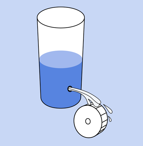
Figure 1-69. If a wheel extracts energy from the flow of water, the flow is now doing some work, which could be measured in watts during a period of time.
Similarly, a battery may seem to be giving power out without taking anything in, but the chemical reactions inside it are changing pure metals into metallic compounds, and the power we get out of a battery is enabled by this change of state. If it’s a rechargeable battery, we have to push power back into it during the charging process, to reverse the chemical reactions.
Going back to the tank of water, suppose we can’t get enough power out of it to turn the wheel. One answer could be to increase the height of the water, to create more force, as in Figure 1-71.

Figure 1-70. To continue getting work out of the system, we have to put work into it.
This would be the same as putting two batteries end to end, positive to negative, in series (as I suggested with lemons, in the lemon battery). Two batteries in series will double the voltage, as shown in Figure 1-72. As long as the resistance in the circuit remains the same, greater voltage will create more amperage, because amperage = voltage / resistance.
Thinking again about the tank analogy, what if we want to run a wheel for twice as long, and we’ve run out of tank capacity? Maybe we should build a second tank, and pipe their outputs through the same hole. Similarly, if you wire two batteries side by side, in parallel, you get the same voltage, but the batteries should last twice as long. Alternatively, the two batteries may be able to deliver more current than if you just used one. See Figure 1-73.

Figure 1-71. The amount of available work will increase with greater water pressure.
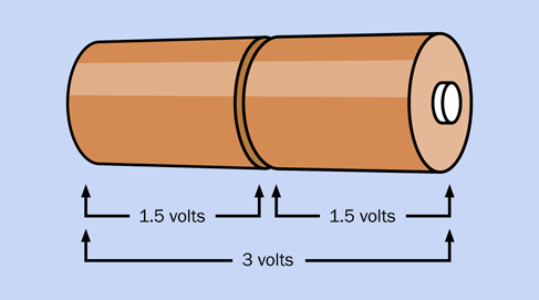
Figure 1-72. Two batteries in series provide twice the voltage of a single battery, provided they are both fully charged.
Summing up:
-
Two batteries in series deliver twice the voltage.
-
Two batteries in parallel can deliver the same current for twice as long, or twice the current for the same amount of time.

Figure 1-73. Batteries in parallel, powering the same load as before, will run it for about twice as long. Alternatively, they can provide twice the current for the same time as a single battery.
That’s enough theory for now. In the next chapter, I’ll continue with some experiments that will build on the foundations of knowledge about electricity, to take you gradually toward gadgets that can be fun and useful.
Cleanup and Recycling
The hardware that you immersed in lemons or lemon juice may be discolored, but it is reusable. Bearing in mind that some zinc ions may have been deposited in the lemons, eating them might not be such a good idea.