
LED LIGHT BRICK
Photography by Garry McLeod
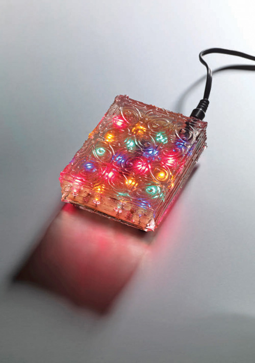
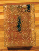
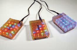
A LITTLE GLOWING FRIEND
Restful, multicolored lights illuminate your path to the kitchen for a late-night snack. Rediscover the night light as an energy-efficient way to brighten your home.
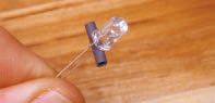
The Little Glowing Friend (I named it after the ever-vigilant blue canary night light in a They Might Be Giants song) uses a single-chip microcontroller to drive 20 LEDs in a variety of patterns. The circuit is embedded in a clear resin casting, creating a lively, self-contained display. The light brick takes about 2 watts of power, and should last more than 10 years in continuous operation.
I gave away 24 of these in 2006; most have been on ever since, and there have been no reported failures. Electricity cost is about $1 a year, for 24×7 operation.
Set up: p.105 Make it: p.106 Use it: p.111
Alden Hart is CTO of Ten Mile Square Technologies, a technology consulting firm that develops systems for media and communications, from the metadata to the metal. In his spare time he combines microcontrollers, LEDs, mechanics, and other small parts in ways that have no practical application.
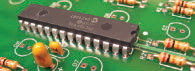
CHIP AHOY
The heart of the Little Glowing Friend is a single-chip microcontroller (PIC16F916) that’s programmed using PIC assembly code.
This chip provides the following functions:
» Drives the LEDs directly from the chip’s output pins
» Provides 20 dimming channels — one for each LED
» Stores and runs the light patterns

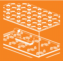
Illustration by Nik Schulz
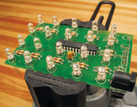
The printed circuit board (PCB) holds the PIC microcontroller, LEDs, current-limiting resistors, a DC power connector, and a few other parts.
The PIC chip is capable of driving up to 25 milliamps (mA) of current per output pin to the LEDs. A current-limiting resistor is used to limit the current flowing through each LED to about 20mA. There are 2 decoupling capacitors that clean up any noise that might be on the power supply. Finally, one resistor is used to hold up the PIC’s reset line so the chip can run, and another is used for the switch.
Because LEDs glow at only one intensity, dimming is accomplished through a variant of pulse width modulation (PWM) — flashing the LED on and off so fast that your eye sees it as a brightness level less than 100%. Once the circuit is working, the entire board is embedded in a clear resin casting that lights up in colorful and interesting ways. You can make your own mold as part of the embedding process, so the brick can take on any shape and texture you desire.
SET UP.

Photography by Alden Hart
MATERIALS
[A] Circuit board from the light brick kit or make your own from the CAD files. Both are available at makezine.com/18/lightbrick.
[B] PIC16F916 microcontroller labeled as U1 on the PCB and the schematic, which is also available at the link above
[C] LEDs, 5mm, 20mA, wide viewing angle, 0.100” lead spacing (20) 5 each, red, yellow, green, and blue, D1–D20 on the PCB and schematic
[D] 100Ω resistors, ¼ watt, 5% carbon film (20) R1–R20
[E] 20kΩ resistors, ¼ watt, 5% carbon film (2) R21, R22
[F] 10μF capacitor, tantalum, 16 volts, 0.1” lead spacing C1
[G] 0.1μF capacitor, monolithic, 0.100” lead spacing C2
[H] Rolling ball tilt switch, 0.100” lead spacing SW1
[I] DC power connector, 2.1mm ID coaxial J1
[J] Rubber bumpers or feet (4)
[K] DC power supply (wall wart), 5V DC regulated, 300mA or more, 2.1mm ID/5.5mm OD, center positive I recommend a 400mA supply because sometimes 300mA ratings are a bit optimistic.
[L] 12” length of #14 solid wire (optional)
[M] 22pF capacitors, monolithic or ceramic disc, 0.100” lead spacing (2, optional) C3, C4
[N] Single-row header connector, 6-pin, 0.100” (ICSP connector)
For molding, use O and P to make your own mold, or use Q instead.
[O] Silicone RTV Mold-Making System, 1lb silicone and 0.1lb catalyst from TAP Plastics (tapplastics.com). My mold used all 16oz; if you design a bigger mold, get more.
[P] Lego bricks for building a mold box
[Q] Self-releasing polypropylene mold, 3”×5”×15” such as Castin’ Craft MC-7, part #43893
[R] Clear-Lite polyester casting resin, 16oz from TAP Plastics
[S] MEKP liquid catalyst, ½oz
[T] Paper cups, 12oz or 16oz (2) for measuring and pouring
[U] Stirring sticks (2)
[V] Clear gloss resin spray (optional) such as Castin’ Craft Resin Spray, for covering imperfections
NOTE: A complete bill of materials and tools, with sources, as well as mold-making and resin-casting instructions, are available at makezine.com/18/lightbrick.
MAKE IT.
BUILD YOUR LED LIGHT BRICK
Time: A Weekend Complexity: Easy to Difficult
START»
Building the light brick involves 3 steps: assemble the PCB, build (or buy) the mold, and cast the piece. The project can be done over a weekend, with each step taking a few hours. Some steps require a wait time, so the total build requires at least 2 days and an overnight to cure the casting. The project is designed at multiple levels of difficulty:
Easy: Assemble the circuit board from a kit and do the acrylic embedding with a pre-made mold.
Medium: Assemble the circuit board from a kit. Then do the mold construction and casting.
Difficult: Program the PIC yourself, to make new patterns. If you want to get really advanced, you can lay out and make your own circuit board — allowing you to change the size and layout and even the number of LEDs. You could also “free-space” the wiring. All the source materials to do this are available online.
For kits, CAD files, firmware, and additional documentation, visit makezine.com/18/lightbrick, or my website at tenmilesquare.com/light-brick.
1. ASSEMBLE THE CIRCUIT BOARD
First, locate the top and bottom of the PCB. The top has the silk-screen and component designators. The bottom has most of the wiring.
1a. Solder the resistors first. Use 100Ω resistors for R1–R20, and 20K resistors for R21 and R22. Resistors are not polarized, so it’s not necessary to line up the color codes, but it does make for a neater job. Tape the resistors tightly to the top of the board using blue masking tape; they’ll trap air bubbles underneath them if they’re not down tight.
Flip the board over and solder. If any of the resistors shifted, heat them up and push them back down. Cut the leads down to the solder joints with wire cutters and remove the blue tape.


1b. Place capacitors C1 and C2 on the board. The tantalum capacitor C1 is polarized and must be inserted as indicated on the board. The positive (+) side of the capacitor goes in the + hole, which is the square one. Tape, solder, and cut as before.

1c. Carefully bend the leads of the PIC to fit the board’s chip hole spacing. Place the PIC with pin 1 (the indented end) pointing to R21 and R22. Carefully solder, without putting too much heat on any pin. Double-check that the polarity is correct before soldering.
1d. Attach the DC power connector J1. Bend the blades out somewhat from the bottom to hold the connector in place. Then solder it in flush to the surface of the board, using plenty of solder to seal the holes.
1e. Attach LEDs D1–D20. The patterns are programmed for the following layout of LEDs:
R B G Y R
Y R B G Y
G Y R B G
B G Y R B

Be sure to test your LEDs for function, and for color if it’s not obvious by the casings. Use an LED tester or just squeeze the leads onto a 3V lithium coin cell.

For proper casting, you want the tops of all the LEDs to be roughly level, and taller than the power connector. The holes in the PCB are sized so that a standard LED lead will stop about 1” above the board. It’s a tight fit, but it works.
If for some reason your LEDs don’t have this stop, you’ll need to make spacers. Make 20 spacers by stripping 2” of insulation from #14 solid wire. Insert the insulation between each LED’s leads, up by the LED case.
Place the LEDs in the board and test the heights against the power connector. Observe correct polarity when placing the LEDs. The long lead is the positive, or anode (A), and goes through the round hole. The short lead is the negative lead, or cathode (K), and goes through the square hole (mnemonic: “cats are negative”). If there’s a flat spot on the LED it will be on the cathode side.
NOTE: The square hole here is designated differently from the capacitor’s, which is the opposite.
1f. Turn the board upside down on a hard, flat surface to ensure all LEDs are lined up. Solder, and clip the leads. Remove any spacers using hemostats or fine pliers. Notice that the common rail is connecting all the positive (+) pins of the LEDs. (In some other LED projects there is a common ground (–) for all the LEDs.)

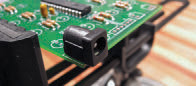
1g. Attach tilt switch SW1. The tilt switch is a rolling ball that runs on a track and closes (activates) when the ball rolls to the base where the wires stick out. It provides user input, acting like a button push or mouse click. The tilt switch is the only component that goes on the bottom of the board. It doesn’t have a polarity. If you want it to activate when you tip the brick back toward the power connector, the switch must angle downward from the rear of the board, as pictured.
If you want this orientation, mount the switch on the bottom of the board through the switch holes labeled SW1. Leave about ¼” of the switch leads exposed between the switch and the board. You’ll need enough room to bend the leads to angle the switch. Use the SW2 position if you’d rather the switch activate 90° from the SW1 position.

1h. If you intend to program the PIC in-circuit, you’ll need to attach capacitors C3 and C4 and the programming header J2 at this point.
1i. Don’t plug the board in just yet. Visually inspect the PIC and the rest of the board for solder bridges (i.e., short circuits in your soldering). Remove any bridges with solder wick (for advice on how to do this, see makezine.com/18/lightbrick).

Next, test the board for a short circuit. Use a continuity tester or ohmmeter to test the power connector’s + and – terminals (located on the bottom of the board).
Finally, test that you have a good power supply. The center pin on the power supply connector should be a stable +5V, and the sleeve is ground. Be sure not to short out these contacts during this test! The board will actually work between about 4V–6V. The PIC doesn’t like voltages above 6V and may blow out if over-voltage is applied.

If the board passes these tests, then plug it in! If the board doesn’t work properly, consult the Troubleshooting section on page 111. Don’t cast the brick until the circuit is working reliably.
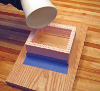
2. MAKE THE MOLD AND CAST THE BRICK
Since we’ve covered moldmaking and casting in a previous issue (see MAKE, Volume 08, page 160), we won’t detail the process here. Complete moldmaking and resin casting instructions for this project are available at makezine.com/18/lightbrick. The easiest way to get a mold is to buy a pre-made one like the MC-7 (see Materials list). It’s 3”×5”×11/16”, a reasonable fit.
I prefer my own mold, for a better fit and a more interesting finished piece. The circuit board is designed to fit nicely into a volume 3”×4¼”×1”–2½” deep, but you can make the master mold any size and shape that will accommodate your board. Remember that the power connector needs to be flush against one side of the finished casting.
You can also house the Little Glowing Friend circuit board in any container you desire, but I like the permanence and uniqueness of the cast brick.
3. FINISHING UP
3a. Don’t get impatient and demold the piece too early, as this can ruin it. Follow the manufacturer’s recommended demold times, and then some. It’s best to leave it overnight or even longer.
Remove the brick when it’s truly cured. It should be fully cooled and hard. Resin hardens from the inside out, so the surface is the last part to harden. This can take well over a day depending on the mix and conditions. Don’t judge by time; demold only when the surface is hard and no longer tacky. Test hardness using a stick, not your finger.
You can speed the surface cure by warming the brick under some lights, but be careful not to overheat the casting or the mold. Don’t leave the lights on overnight or unattended.
3b. Remove the tape from the power connector using hemostats. You may also need a knife if it’s gotten coated over.
3c. Even though the brick is hard at this point, the finish is still fragile. It will pick up fingerprints and will pit with dust. It’s best to handle it only by the edges. You may want to “tent” it under wax paper and continue the cure. Don’t let the wax paper touch the surface, or it will leave marks. Optionally, you can spray on a surface coat of resin at this point to protect the finish, but be aware that this may cloud the surface. Use sparingly.
3d. Apply the bumper feet to the bottom and you’re done.
NOW GO USE IT »
FINISH X
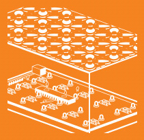
MEET PEGGY, OUR COVER SPOKESLIGHT

Photograph by Garry McLeod
Geek super-couple Windell Oskay and Lenore Edman like to trip the light (emitting diode) fantastic. One of their first projects to blip the global DIY radar was their interactive LED dining table, with 448 LEDs under frosted glass.
After the bizarre Mooninite Invasion of 2007, when some Lite-Brite-type signs got the better of Boston’s finest, Oskay and Edman, who invent under the name Evil Mad Scientist Laboratories (evilmadscientist.com), were inspired to create Peggy, a plug-and-play (or plug-and-program) LED “pegboard” you build from a kit.
With the success of Peggy, the white coats at EMS Labs knew they were on to something. “It became clear that there was room for something more advanced,” says Oskay. “So we made the Peggy 2, which has the same basic design but supports simple animations.”
Recognizing the strength of the Arduino community, they designed Peggy 2 to be programmed through the Arduino environment. “The architecture is similar to that of an Arduino clone, but with substantial onboard LED driving hardware,” he says.
So how long does it take to build a board with up to 625 LEDs? An hour or two on the rest of the board, and then the time to solder on the lights. You decide how many you want to install — the “resolution” of your screen. Only rudimentary soldering skills are required. To create a basic sign lighting every LED, no programming is needed. To animate Peggy, and create other lighting effects and control, programming can be done via Arduino.
“People love interacting with the Peggy,” says Oskay. “There’s something about giant pixels — especially giant physical pixels that you can touch — that really grabs people. We love seeing what folks do with it. One builder, Jay Clegg, even figured out how to display grayscale video on the Peggy 2.”
The original Peggy is $80 and Peggy 2 is $95, LEDs not included. Both kits are available in the Maker Shed (makershed.com) and the Evil Mad Science Shop (evilmadscience.com).
Gareth Branwyn is senior editor at MAKE.
USE IT.
FIRE UP YOUR LITTLE GLOWING FRIEND

Plug it in and watch it go! Activating the tilt switch will cycle the device between power off and 4 different lighting programs — Waves, Colors, Calm, and Frenetic.
TROUBLESHOOTING
If, for some reason, the board doesn’t light when you test it (in Step 1i, before casting the brick, of course), check the following:
» Ensure that all leads go through the holes, and check that none of the PIC leads have folded up under the chip body. They should all be visible from the bottom of the board.
» Inspect the bottom of the board to ensure that all connections are soldered.
» Check the polarization and orientation of components C1, U1, and D1–D20.
» Check that there are no solder bridges (two points connected that shouldn’t be).
» Check that the power supply is plugged in and outputting between 4 and 6 volts. Use a volt/ohm meter (VOM) or multimeter.
» Check that the center pin of the power supply is positive, not negative (reversed polarity).
» Check that the board is not short-circuited by testing the + and – terminals on the bottom of the board.
If some LEDs are working but not others, try doing the following:
» Test the LED individually. Apply voltage from a coin cell across the LED terminals.
» Next, test with a VOM that there is 100 ohms of resistance between the LED’s negative terminal (the square hole) and the PIC pin. Trace the circuit visually or use the schematic diagram.
Photography by Alden Hart
RESOURCES
![]() For a materials and tools list, sources, CAD files, a schematic, and moldmaking and resin-casting instructions, visit makezine.com/18/lightbrick.
For a materials and tools list, sources, CAD files, a schematic, and moldmaking and resin-casting instructions, visit makezine.com/18/lightbrick.
Connecting LEDs: makezine.com/go/led2 Free-space wiring example: instructables.com/id/3x3x3-LED-Cube
![]() Video on how to remove solder bridges with solder wick (see 7:45): makezine.com/go/solder
Video on how to remove solder bridges with solder wick (see 7:45): makezine.com/go/solder
Thanks to Daniel Klaussen for helping us in testing this project.