Chapter 7: Networking with Linux
Linux networking is a vast domain. The last decades have seen countless volumes and references written about Linux network administration internals. Sometimes, the mere assimilation of essential concepts could be overwhelming for both novice and advanced users. This chapter provides a relatively concise overview of Linux networking, focusing on network communication layers, sockets and ports, networking services and protocols, virtual private networks (VPNs), and network security.
We hope that the content presented in this chapter is both a comfortable introduction to basic Linux networking principles for a novice user and a good refresher for an advanced Linux administrator.
In this chapter, we cover the following topics:
- Exploring basic networking—focusing on computer networks, networking models, protocols, network addresses, and ports. We also cover some practical aspects of configuring Linux network settings using the command-line terminal.
- Working with networking services—introducing common networking servers running on Linux, such as Domain Host Configuration Protocol (DHCP) servers, Domain Name System (DNS) servers, file-sharing servers, remote-access servers, and so on.
- Understanding network security—with a special emphasis on VPNs.
Technical requirements
Throughout this chapter, we'll be using the Linux command line to some extent. A working Linux distribution, installed on either a virtual machine (VM) or a desktop platform, is highly recommended. If you don't have one already, Chapter 1, Installing Linux and Setting Up the Environment, will guide you through the installation process. Most of the commands and examples illustrated in this chapter use Ubuntu and CentOS, but the same would apply to any other Linux platform.
Exploring basic networking
Today, it's almost inconceivable to imagine a computer not connected to some sort of network or the internet. Our ever-increasing online presence, cloud computing, mobile communications, and Internet of Things (IoT) would not be possible without the highly distributed, high-speed, and scalable networks serving the underlying data traffic, yet the basic networking principles behind the driving force of the modern-day internet are decades old. Obviously, networking and communication paradigms will continue to evolve, but some of the original primitives and concepts will still have a long-lasting effect in shaping the building blocks of future communications.
This section will introduce you to a few of these networking essentials and, hopefully, spark your curiosity for further exploration. Let's start with computer networks.
Computer networks
A computer network is a group of two or more computers (or nodes) connected via a physical medium (cable, wireless, optical) and communicating with each other using a standard set of agreed-upon communication protocols. At a very high level, a network communication infrastructure includes computers, devices, switches, routers, Ethernet or optical cables, wireless environments, and all sorts of network equipment.
Beyond the physical connectivity and arrangement, networks are also defined by a logical layout via network topologies, tiers, and the related data flow. An example of a logical networking hierarchy is the three-tiered layering of the demilitarized zone (DMZ), firewall, and internal networks. The DMZ is an organization's outward-facing network, with an extra security layer against the public internet. A firewall controls the network traffic between the DMZ and the internal network.
Network devices are identified by network addresses and hostnames. Network addresses assist with locating nodes on the network using communication protocols, such as the Internet Protocol (IP) (see more on IP in the TCP/IP protocols section, later in this chapter). Hostnames are user-friendly labels associated with devices, easier to remember than network addresses.
A common classification criterion looks at the scale and expansion of computer networks. We introduce local area networks (LANs) and wide area networks (WANs) next.
LANs
A LAN represents a group of devices connected and located in a single physical location, such as a private residence, school, or office. A LAN can be of any size, ranging from a home network with only a few devices to large-scale enterprise networks with thousands of users and computers.
Regardless of the network size, a LAN's essential characteristic is that it connects devices in a single, limited area. Examples of LANs include the home network of a single-family residence or your local coffee shop's free wireless service.
For more information about LANs, you can refer to https://www.cisco.com/c/en/us/products/switches/what-is-a-lan-local-area-network.html.
When a computer network spans multiple regions or multiple interconnected LANs, WANs come into play.
WANs
A WAN is usually a network of networks, with multiple or distributed LANs communicating with each other. In this sense, we regard the internet as the world's largest WAN.
An example of WAN is the computer network of a multinational company's geographically distributed offices worldwide. Some WANs are built by service providers, to be leased to various businesses and institutions around the world.
WANs have several variations, depending on their type, range, and use. Typical examples of WANs include personal area networks (PANs), metropolitan area networks (MANs), and cloud or internet area networks (IANs).
For more information about WANs, you can refer to https://www.cisco.com/c/en/us/products/switches/what-is-a-wan-wide-area-network.html.
We think that an adequate introduction to basic networking principles should always include a brief presentation of the theoretical model governing network communications in general. Let's look at this next.
The OSI model
The Open Systems Interconnection (OSI) model is a theoretical representation of a multilayer communication mechanism between computer systems interacting over a network. The OSI model was introduced in 1983 by the International Organization for Standardization (ISO) to provide a standard for different computer systems to communicate with each other.
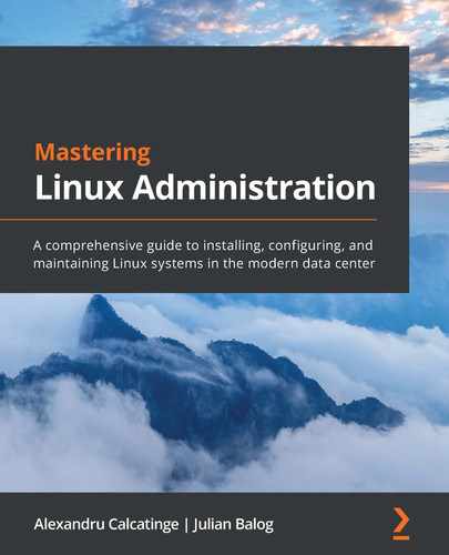
We could regard the OSI model as a universal framework for network communications. As the following screenshot shows, the OSI model defines a stack of seven layers, directing the communication flow:
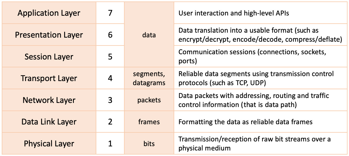
Figure 7.1 – The OSI model
In the layered view shown in the preceding diagram, the communication flow moves from top to bottom (on the transmitting end) or bottom to top (on the receiving end). Let's look at each of these layers and describe their functionality in shaping network communication.
The physical layer
The physical layer (or Layer 1) consists of the networking equipment or infrastructure connecting the devices and serving the communication, such as cables, wireless or optical environments, connectors, and switches. This layer handles the conversion between raw bit streams and the communication medium while regulating the corresponding bit-rate control. (The communication medium includes electrical, radio, or optical signals.)
Examples of protocols operating at the physical layer include Ethernet, Universal Serial Bus (USB), and Digital Subscriber Line (DSL).
The data link layer
The data link layer (or Layer 2) establishes a reliable data flow between two directly connected devices on a network, either as adjacent nodes in a WAN or as devices within a LAN. One of the data link layer's responsibilities is flow control, adapting to the physical layer's communication speed. On the receiving device, the data link layer corrects communication errors that originated in the physical layer. The data link layer consists of the following subsystems:
- Media access control (MAC)—This subsystem uses MAC addresses to identify and connect devices on the network. It also controls the device access permissions to transmit and receive data on the network.
- Logical link control (LLC)—This subsystem identifies and encapsulates network layer protocols and performs error checking and frame synchronization while transmitting or receiving data.
The protocol data units controlled by the data link layer are also known as frames. A frame is a data transmission unit acting as a container for a single network packet. Network packets are processed at the next OSI level (network layer). When multiple devices access the same physical layer simultaneously, frame collisions may occur. Data link layer protocols can detect and recover from such collisions and further reduce or prevent their occurrence.
An example of data link protocol is the Point-to-Point Protocol (PPP), a binary networking protocol used in high-speed broadband communication networks.
The network layer
The network layer (or Layer 3) discovers the optimal communication path (or route) between devices on a network. This layer uses a routing mechanism based on the IP addresses of the devices involved in the data exchange, to move data packets from source to destination.
On the transmitting end, the network layer disassembles the data segments that originated in the transport layer (Layer 4) into network packets. On the receiving end, the data frames are reassembled from the layer below (data link layer) into packets.
A protocol operating at the network layer is the Internet Control Message Protocol (ICMP). ICMP is used by network devices to check the availability of other devices (or IP addresses) on the network. ICMP reports an error when a requested endpoint is not available.
The transport layer
The transport layer (or Layer 4) operates with data segments or datagrams. This layer is mainly responsible for transferring data from a source to a destination and guaranteeing a specific quality of service (QoS). On the transmitting end, data that originated from the layer above (session layer) is disassembled into segments. On the receiving end, the transport layer reassembles the data packets received from the layer below (network layer) into segments.
The transport layer maintains the reliability of the data transfer through flow-control and error-control functions. The flow-control function adjusts the data transfer rate between endpoints with different connection speeds, to avoid a sender overwhelming the receiver. When the data received is incorrect, the error-control function may request the retransmission of data.
Examples of transport layer protocols include the Transmission Control Protocol (TCP) and the User Datagram Protocol (UDP).
The session layer
The session layer (or Layer 5) controls the lifetime of the connection channels (or sessions) between devices communicating on a network. At this layer, sessions or network connections are usually defined by network addresses, sockets, and ports. We'll explain each of these concepts later in this chapter. The session layer is responsible for the integrity of the data transfer within a communication channel or session. For example, if a session is interrupted, the data transfer resumes from a previous checkpoint.
Some typical session layer protocols are the Remote Procedure Call (RPC) protocol used by interprocess communications, and Network Basic Input/Output System (NetBIOS), which is a file-sharing and name-resolution protocol.
The presentation layer
The presentation layer (or Layer 6) acts as a data translation tier between the application layer above and the session layer below. On the transmitting end, this layer formats the data into a system-independent representation before sending it across the network. On the receiving end, the presentation layer transforms the data into an application-friendly format. Examples of such transformations are encryption and decryption, compression and decompression, encoding and decoding, and serialization and deserialization. Usually, there is no substantial distinction between the presentation and application layers, mainly due to the relatively tight coupling of the various data formats with the applications consuming them. Standard data representation formats include American Standard Code for Information Interchange (ASCII), Extensible Markup Language (XML), JavaScript Object Notation (JSON), Joint Photographic Experts Group (JPEG), ZIP, and so on.
The application layer
The application layer (or Layer 7) is the closest to the end user in the OSI model. Layer 7 collects or provides the input or output of application data in some meaningful way. This layer does not contain or run the applications themselves. Instead, Layer 7 acts as an abstraction between applications, implementing a communication component and the underlying network. Typical examples of applications interacting with the application layer are web browsers and email clients.
A few examples of Layer 7 protocols are the DNS protocol; the HyperText Transfer Protocol (HTTP); the File Transfer Protocol (FTP); and the Post Office Protocol (POP), Internet Message Access Protocol (IMAP), Simple Mail Transfer Protocol (SMTP) email messaging protocols.
Before wrapping up, we should call out that the OSI model is a generic representation of networking communication layers and provides the theoretical guidelines of how network communication works. A similar—but more practical—illustration of the networking stack is the TCP/IP model, which we'll explore in the next section.
Both models are useful when it comes to network design, implementation, troubleshooting, and diagnostics. The OSI model gives network operators a good understanding of the full networking stack, from the physical medium to the application layer, each level with its Protocol Data Units (PDUs) and communication internals. The TCP/IP model is somewhat simplified, with a few of the OSI model layers collapsed into one, and it takes a rather protocol-centric approach to network communications.
The TCP/IP model
The TCP/IP model is a four-layer interpretation of the OSI networking stack, where some of the equivalent OSI layers appear consolidated, as shown in the following screenshot:
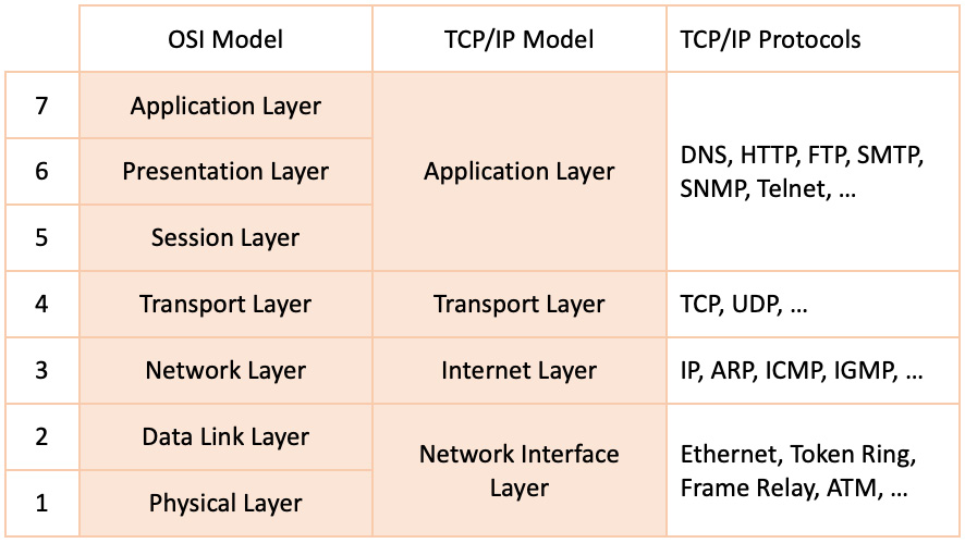
Figure 7.2 – The OSI and TCP/IP models
Chronologically, the TCP/IP model is older than the OSI model. It was first suggested by the US Department of Defense (DoD) as part of an internetwork project developed by the Defense Advanced Research Projects Agency (DARPA). This project eventually became the modern-day internet.
The TCP/IP model layers encapsulate similar functions to their counterpart OSI layers. Here's a brief summary of each layer in the TCP/IP model.
The network interface layer
The network interface layer is responsible for data delivery over a physical medium (such as wire, wireless, optical). Networking protocols operating at this layer include Ethernet, Token Ring, and Frame Relay. This layer maps to the composition of the physical and data link layers in the OSI model.
The internet layer
The internet layer provides connectionless data delivery between nodes on a network. Connectionless protocols describe a network communication pattern where a sender transmits data to a receiver without a prior arrangement between the two. This layer is responsible for disassembling data into network packets at the transmitting end and reassembling on the receiving end. The internet layer uses routing functions to identify the optimal path between the network nodes. This layer maps to the network layer in the OSI model.
The transport layer
The transport layer (also known as the transmission layer or the host-to-host layer) is responsible for maintaining the communication sessions between connected network nodes. The transport layer implements error-detection and correction mechanisms for reliable data delivery between endpoints. This layer maps to the transport layer in the OSI model.
The application layer
The application layer provides the data communication abstraction between software applications and the underlying network. This layer maps to the composition of the session, presentation, and application layers in the OSI model.
The TCP/IP model is a protocol-centric representation of the networking stack. This model served as the foundation of the internet by gradually defining and developing networking protocols required for internet communications. These protocols are collectively referred to as the IP suite.
The following section describes some of the most common networking protocols.
TCP/IP protocols
In this section, we describe some widely used networking protocols. The reference here should not be regarded as an all-encompassing guide. There are a vast number of TCP/IP protocols, and a comprehensive study is beyond the scope of this chapter. Nevertheless, there are a handful of protocols worth exploring that are frequently at work in everyday network communication and administration workflows.
The following sections briefly describe each TCP/IP protocol with its related Request for Comments (RFC) identifier for more information. The RFC represents the detailed technical documentation—of a protocol, in our case—usually authored by the Internet Engineering Task Force (IETF). For more information about RFC, please refer to https://www.ietf.org/standards/rfcs/.
IP
IP (RFC 791) identifies network nodes based on fixed-length addresses, also known as IP addresses. IP addresses are described in more detail later in this chapter. The IP protocol uses datagrams as the data transmission unit and provides fragmentation and reassembly capabilities of large datagrams to accommodate small-packet networks (and avoid transmission delays). The IP protocol also provides routing functions to find the optimal data path between network nodes. IP operates at the network layer (3) in the OSI model.
ARP
The Address Resolution Protocol (ARP) (RFC 826) is used by the IP protocol to map IP network addresses (specifically, IP version 4 (IPv4)) to device MAC addresses used by a data link protocol. ARP operates at the data link layer (2) in the OSI model.
NDP
The Neighbor Discovery Protocol (NDP) (RFC 4861) is like the ARP protocol, and it also controls IP version 6 (IPv6) address mapping. NDP operates within the data link layer (2) in the OSI model.
ICMP
ICMP (RFC 792) is a supporting protocol for checking the availability of network devices based on IP address. When a device or node is not reachable within a given timeout, ICMP reports an error. ICMP operates at the network layer (3) in the OSI model.
TCP
TCP (RFC 793) is a connection-oriented, highly reliable communication protocol. TCP requires a logical connection (such as a handshake) between the nodes before initiating the data exchange. TCP operates at the transport layer (4) in the OSI model.
UDP
UDP (RFC 768) is a connectionless communication protocol. UDP has no handshake mechanism (compared to TCP). Consequently, with UDP there's no guarantee of data delivery. UDP uses datagrams as the data transmission unit, and it's suitable for network communications where error checking is not critical. UDP operates at the transport layer (4) in the OSI model.
DHCP
DHCP (RFC 2131) provides a framework for requesting and passing host configuration information required by devices on a TCP/IP network. DHCP enables the automatic (dynamic) allocation of reusable IP addresses and other configuration options. DHCP is considered an application layer (7) protocol in the OSI model, but the initial DHCP discovery mechanism operates at the data link layer (2).
DNS
DNS (RFC 2929) is a protocol acting as a network address book, where nodes in the network are identified by human-readable names instead of IP addresses. According to the IP protocol, each device on a network is identified by a unique IP address. When a network connection specifies the remote device's hostname (or domain name) before the connection is established, DNS translates the domain name (such as dns.google.com) to an IP address (such as 8.8.8.8). The DNS protocol operates at the application layer (7) in the OSI model.
HTTP
HTTP (RFC 2616) is the vehicular language of the internet. HTTP is a stateless application-level protocol based on request and response between a client application (for example, a browser) and a server endpoint (for example, a web server). HTTP supports a wide variety of data formats, ranging from text to images and video streams. HTTP operates at the application layer (7) in the OSI model.
FTP
FTP (RFC 959) is a standard protocol for transferring files requested by an FTP client from an FTP server. FTP operates at the application layer (7) in the OSI model.
TELNET
The Terminal Network protocol (TELNET) (RFC 854) is an application-layer protocol providing a bidirectional text-oriented network communication between a client and a server machine, using a virtual terminal connection. TELNET operates at the application layer (7) in the OSI model.
SSH
Secure Shell (SSH) (RFC 4253) is a secure application-layer protocol, encapsulating strong encryption and cryptographic host authentication. SSH uses a virtual terminal connection between a client and a server machine. SSH operates at the application layer (7) in the OSI model.
SMTP
SMTP (RFC 5321) is an application-layer protocol for sending and receiving emails between an email client (for example, Outlook) and an email server (such as Exchange Server). SMTP supports strong encryption and host authentication. SMTP acts at the application layer (7) in the OSI model.
SNMP
The Simple Network Management Protocol (SNMP) (RFC 1157) is used for remote device management and monitoring. SNMP operates at the application layer (7) in the OSI model.
NTP
The Network Time Protocol (NTP) (RFC 5905) is an internet protocol used for synchronizing the system clock of multiple machines across a network. NTP operates at the application layer (7) in the OSI model.
Most of the internet protocols enumerated previously use the IP protocol to identify devices participating in a communication. Devices on a network are uniquely identified by an IP address. Let's have a closer examination of these network addresses.
IP addresses
The IP address is a fixed-length unique identifier (UID) of a device in a network. Devices locate and communicate with each other based on IP addresses. The concept of an IP address is very similar to a postal address of a residence, whereby a mail or a package would be sent to that destination based on its address.
Initially, IP defined the IP address as a 32-bit number known as an IPv4 address. With the growth of the internet, the total number of IP addresses in a network has been exhausted. To address this issue, a new version of the IP protocol devised a 128-bit numbering scheme for IP addresses. A 128-bit IP address is also known as an IPv6 address.
In the next sections, we'll take a closer look at the networking constructs playing an important role in IP addresses, such as IPv4 and IPv6 address formats, network classes, subnetworks, and broadcast addresses.
IPv4 addresses
An IPv4 address is a 32-bit number (4 bytes) usually expressed as four groups of 1-byte (8 bits) numbers, separated by a dot (.). Each number in these four groups is an integer between 0 and 255. Here's an example of an IPv4 address:
192.168.1.53
The following illustration shows a binary representation of an IPv4 address:
Figure 7.3 – Network classes
The IPv4 address space is limited to 4,294,967,296 (232) addresses (roughly 4 billion). Of these, approximately 18 million are reserved for special purposes (for example, private networks), and about 270 million are multicast addresses.
A multicast address is a logical identifier of a group of IP addresses. For more information on multicast addresses, please refer to RFC 6308 (https://tools.ietf.org/html/rfc6308).
Network classes
In the early stages of the internet, the highest-order byte (first group) in the IPv4 address indicated the network number. The subsequent bytes further express the network hierarchy and subnetworks, with the lowest-order byte identifying the device itself. This scheme soon proved insufficient for network hierarchies and segregations, as it only allowed for 256 (28) networks, denoted by the leading byte of the IPv4 address. As additional networks were added, each with its own identity, the IP address specification needed a special revision to accommodate a standard model. The Classful Network specification introduced in 1981 addressed the problem by dividing the IPv4 address space into five classes based on the leading 4 bits of the address, as illustrated in the following screenshot:

Figure 7.4 – Network classes
For more information on network classes, please refer to RFC 870 (https://tools.ietf.org/html/rfc870). In the preceding table, the last column specifies the default subnet mask for each of these network classes. We'll look at subnets (or subnetworks) next.
Subnetworks
Subnetworks (or subnets) are logical subdivisions of an IP network. Subnets were introduced with the purpose of identifying devices that belong to the same network. The IP addresses of devices in the same network have an identical most-significant group. The subnet definition yields a logical division of an IP address in two fields: the network identifier and a host identifier. The numerical representation of the subnet is called a subnet mask or netmask. The following table gives an example of a network identifier and a host identifier:
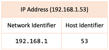
Figure 7.5 – Subnet with network and host identifiers
With our IPv4 address (192.168.1.53), we could devise a network identifier of 192.168.1 and the host identifier as 53. The resulting subnet mask is this:
192.168.1.0
We dropped the least significant group in the subnet mask, representing the host identifier (53), and replaced it with 0. The 0 in this case indicates the starting address in the subnet. In other words, any host identifier value in the range of 0 – 255 is allowed in the subnetwork. For example, the IP address of 192.168.1.92 is a valid (and accepted) IP address in the 192.168.1.0 network.
An alternative representation of subnets uses so-called Classless Inter-Domain Routing (CIDR) notation. CIDR represents an IP address as the network address (prefix) followed by a slash (/) and the bit-length of the prefix. In our case, the CIDR notation of the 192.168.1.0 subnet is this:
192.168.1/24
The first three groups in the network address make up for 3 x 8 = 24 bits, hence the /24 notation.
Usually, subnets are planned with the host identifier address as a starting point. Back to our example, suppose we wanted our host identifier addresses in the network to start with 100 and end with 125.
The binary representation of 192.168.1.100 is this:
11000000.10101000.00000001.01100100
The last group in the preceding sequence (highlighted) represents the host identifier (100). The closest binary value to the reserved 99 addresses that would not be permitted in our subnet is 96 = 64 + 32. The equivalent binary value is as follows:
11100000
In other words, the three most significant bits in the host identifier are reserved. Reserved bits in the subnet representation are shown as 1. These bits would be added to the 24 already reserved bits of the network address (192.168.1), accounting in total for 27 = 24 + 3 bits. Here's the equivalent representation:
11111111.11111111.11111111.11100000
Consequently, the resulting netmask is this:
255.255.255.224
The CIDR notation of the corresponding subnet is shown here:
192.168.1.96/27
The remaining 5 bits in the host identifier's group account for 25 = 32 possible addresses in the subnet, starting with 97. This would limit the maximum host identifier value to 127 = 96 + 32 – 1. (We subtract 1 to account for the starting number of 97 included in the total of 32). In this range of 32 addresses, the last IP address is reserved as a broadcast address, shown here:
192.168.1.127
A broadcast address is reserved as the highest number in a network or subnet, when applicable. Back to our example, excluding the broadcast address, the maximum host IP address in the subnet is this:
192.168.1.126
You can learn more about subnets in RFC 1918 (https://tools.ietf.org/html/rfc1918). Since we mentioned the broadcast address, let's have a quick look at it.
Broadcast addresses
A broadcast address is a reserved IP address in a network or subnetwork, used to transmit a collective message (data) to all devices belonging to the network. The broadcast address is the last IP address in the network or subnet, when applicable.
For example, the broadcast address of the 192.168.1.0/24 network is 192.168.1.255. In our example in the previous section, the broadcast address of the 192.168.1.96/27 subnet is 192.168.1.127 (127 = 96 + 32 – 1).
For more information on broadcast addresses, please visit https://en.wikipedia.org/wiki/Broadcast_address.
IPv6 addresses
An IPv6 address is a 128-bit number (16 bytes) usually expressed as up to eight groups of 2-byte (16-bits) numbers, separated by a column (:). Each number in these eight groups is a hexadecimal number, with values between 0000 and FFFF. Here's an example of an IPv6 address:
2001:0b8d:8a52:0000:0000:8b2d:0240:7235
An equivalent representation of the preceding IPv6 address is shown here:
2001:b8d:8a52::8b2d:240:7235/64
In the second representation, the leading zeros are omitted, and the all-zero groups (0000:0000) are collapsed into an empty group (::). The /64 notation at the end represents the prefix length of the IPv6 address. The IPv6 prefix length is the equivalent of the CIDR notation of IPv4 subnets. For IPv6, the prefix length is expressed as an integer value between 1 and 128.
In our case, with the prefix length of 64 (4 x 16) bits, the subnet looks like this:
2001:b8d:8a52::
The subnet represents the leading four groups (2001, 0b8d, 8a52, 0000), a total of 4 x 16 = 64 bits. In the shortened representation of the IPv6 subnet, the leading zeros are omitted and the all-zero group is collapsed to ::.
Subnetting with IPv6 is very similar to IPv4. We won't go into the details here, since the related concepts are already presented in the IPv4 section. For more information on IPv6, please refer to RFC 2460 (https://tools.ietf.org/html/rfc2460).
After becoming familiar with IP addresses, it is fitting to introduce some of the related network constructs—sockets and ports—serving the software implementation of IP addresses.
Sockets and ports
A socket is a software data structure representing a network node for communication purposes. Although a programming concept, in Linux a network socket is ultimately a file descriptor controlled via a network application programming interface (API). A socket is used by an application process for transmitting and receiving data. An application can create and delete sockets. A socket cannot be active (sending or receiving data) beyond the lifetime of the process that created the socket.
Network sockets operate at the transport-layer level in the OSI model. There are two endpoints to a socket connection—a sender and a receiver. Both the sender and receiver have their own IP address. Consequently, a critical piece of information in the socket data structure is the IP address of the endpoint owning the socket.
Both endpoints create and manage their sockets via the network processes using these sockets. The sender and receiver may agree upon using multiple connections to exchange data. Some of these connections may even run in parallel. How do we differentiate between these socket connections? The IP address by itself is not sufficient, and this is where ports come into play.
A network port is a logical construct used to identify a specific process or network service running on a host. A port is an integer value in the range of 0 – 65535. Usually, ports in the range of 0 – 1024 are assigned to the most used services on a system. These ports are also called well-known ports. Here are a few examples of well-known ports and the related network service for each of them:
- 25—SMTP
- 21—FTP
- 22—SSH
- 53—DNS
- 67, 68—DHCP (client = 68, server = 67)
- 80—HTTP
- 443—HTTP Secure (HTTPS)
Port numbers beyond 1024 are for general use and are also known as ephemeral ports.
A port is always associated with an IP address. Ultimately, a socket is a combination of an IP address and a port. For more information on network sockets, you can refer to RFC 147 (https://tools.ietf.org/html/rfc147). For well-known ports, see RFC 1340 (https://tools.ietf.org/html/rfc1340).
Let's put to work the knowledge we gained so far, by looking next at how to configure the local networking stack in Linux.
Linux network configuration
This section describes the TCP/IP network configuration for Ubuntu and CentOS platforms, using their latest released versions to date. The same concepts would apply for most Linux distributions, albeit some of the network configuration utilities and files involved could be different.
We use the ip command-line utility to retrieve the system's current IP addresses, as follows:
ip addr
An example output is shown here:
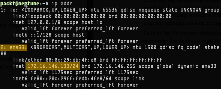
Figure 7.6 – Retrieving the current IP addresses with the ip command
We highlighted some relevant information, such as the network interface ID (2: ens33) and the IP address with the subnet prefix (172.16.146.133/24).
Let's look at Ubuntu's network configuration next. At the time of this writing, the current released version of Ubuntu is 20.04.
Ubuntu network configuration
Ubuntu 20.04 provides the netplan command-line utility for easy network configuration. netplan uses a YAML Ain't Markup Language (YAML) configuration file to generate the network interface bindings. The netplan configuration file(s) is in the /etc/netplan/ directory, as shown in the following code snippet:
ls /etc/netplan/
In our case, the configuration file is 00-installer-config.yaml, as illustrated here:
Figure 7.7 – Retrieving the netplan configuration file(s)
Changing the network configuration involves editing the netplan YAML configuration file. As a good practice, we should always make a backup of the current configuration file before making changes.
We'll look at dynamic IP addressing first.
Dynamic IP
To enable a dynamic (DHCP) IP address, we edit the netplan configuration file and set the dhcp4 attribute to true for the network interface of our choice (ens33 in our case), as follows:
sudo nano /etc/netplan/00-installer-config.yaml
Here's the related configuration excerpt, with the relevant points highlighted:

Figure 7.8 – Enabling DHCP in the netplan configuration
After saving the configuration file, we can test the related changes with the following command:
sudo netplan try
We get the following response:
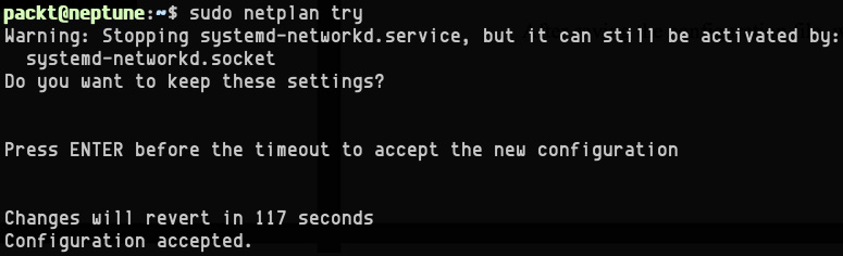
Figure 7.9 – Testing and accepting the netplan configuration changes
netplan validates the new configuration and prompts for accepting the changes. The following command applies the current changes to the system:
sudo netplan apply
Next, we configure a static IP address using netplan.
Static IP
To set the static IP address of a network interface, we start by editing the netplan configuration YAML file, as follows:
sudo nano /etc/netplan/00-installer-config.yaml
Here's a configuration example with a static IP address of 172.16.146.100/24:

Figure 7.10 – Static IP configuration example with netplan
After saving the configuration, we can test and accept, and then apply changes, as we did in the Dynamic IP section, with the following commands:
sudo netplan try
sudo netplan apply
For more information on the netplan command-line utility, see netplan --help or the related system manual (man netplan).
We'll look at the CentOS network configuration next. At the time of this writing, the current released version of Red Hat Enterprise Linux (RHEL)/CentOS is CentOS 8.
CentOS network configuration
There are two ways to configure and manage network interfaces in CentOS 8, as outlined here:
- Manually editing the network interface files in /etc/sysconfig/network-scripts/
- Using the nmcli command-line utility
The network configuration files are in the /etc/sysconfig/networks-scripts/ directory, as shown in the following code snippet. They are named according to the corresponding network interface ID and prefixed with ifcfg. In our case, we retrieve the configuration file with the following command:
ls /etc/sysconfig/networks-scripts/
The output is as follows:

Figure 7.11 – Retrieving the network configuration files
The only network configuration file is ifcfg-ens33 and this corresponds to the ens33 network interface.
Let's look at dynamic IP addressing first.
Dynamic IP
Here's a DHCP configuration example for ifcfg-ens33:
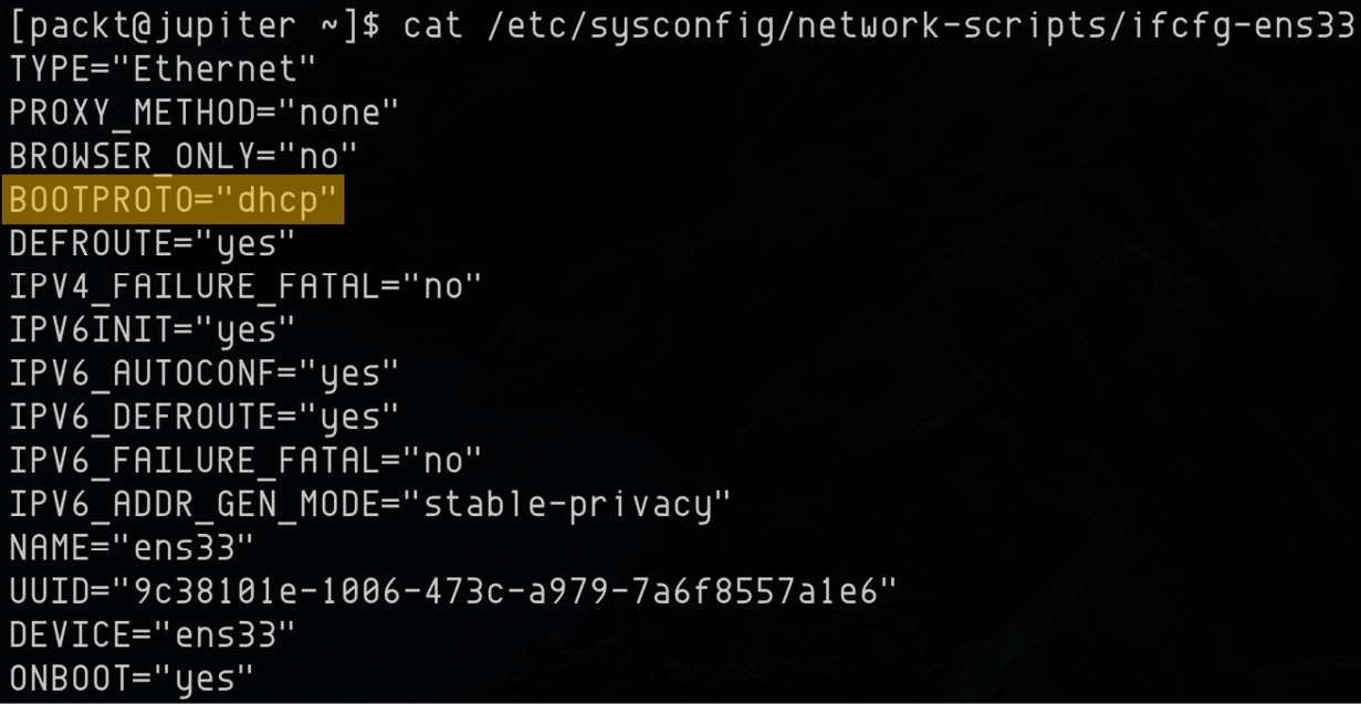
Figure 7.12 – Dynamic IP configuration
The dynamic IP address is enabled with BOOTPROTO="dhcp". The possible values for BOOTPROTO are listed as follows:
- dhcp—uses the DHCP protocol to set a dynamic IP address
- bootp—uses the Bootstrap (BOOTP) protocol to set a dynamic IP address
- none—uses a static IP address
To apply the changes, we need to restart (down and up) the related network interface (ens33) with the following code:
sudo nmcli connection down ens33
sudo nmcli connection up ens33
To configure a dynamic IP address using ncmli, we run the following command:
sudo nmcli connection modify ens33 IPv4.method auto
The IPv4.method auto directive enables DHCP.
Let's configure a static IP address next.
Static IP
Here's a static IP configuration example for ifcfg-ens33:

Figure 7.13 – Static IP configuration
The relevant changes are highlighted. DHCP is disabled with BOOTPROTO="none". IPADDR and PREFIX set the static IP address (172.16.146.136/24). We also have the gateway and DNS servers specified.
The changes are saved with the following code:
sudo nmcli connection down ens33
sudo nmcli connection up ens33
To perform the equivalent static IP address changes using ncmli, we need to run multiple commands. First, we set the static IP address, as follows:
sudo nmcli connection modify ens33 IPv4.address 172.16.146.136/24
If we had no previous static IP address configured, we recommend saving the preceding change before proceeding with the next steps. The changes are saved with the following code:
sudo nmcli connection down ens33
sudo nmcli connection up ens33
Next, we set the gateway and DNS IP addresses, as follows:
sudo nmcli connection modify ens33 IPv4.gateway 172.16.146.2
sudo nmcli connection modify ens33 IPv4.dns 8.8.8.8
Finally, we disable DHCP with the following code:
sudo nmcli connection modify ens33 IPv4.method manual
After these changes, we need to restart the ens33 network interface with the following code:
sudo nmcli connection down ens33
sudo nmcli connection up ens33
Next, we'll take a look at how to change the hostname of a Linux machine.
Hostname configuration
To retrieve the current hostname on a Linux machine, we can use either the hostname or hostnamectl command, as follows:
hostname
In our case, the response is this:
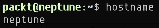
Figure 7.14 – Retrieving the current hostname
The most convenient way to change the hostname is with the hostnamectl command. We can change the hostname to jupiter with the following code:
sudo hostnamectl set-hostname jupiter
Let's verify the hostname change with the hostnamectl command this time, as follows:
hostnamectl
The output of the hostnamectl command provides more detailed information compared to the hostname command, as we can see here:

Figure 7.15 – Retrieving the current hostname with the hostnamectl command
Alternatively, we can use the hostname command to change the hostname temporarily, as follows:
sudo hostname jupiter
But this change would not survive a reboot unless we also change the hostname in the /etc/hostname and /etc/hosts files, as follows:
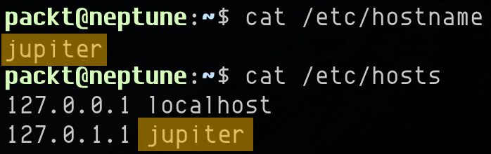
Figure 7.16 – The /etc/hostname and /etc/hosts files
After the hostname reconfiguration, a logout followed by a login would usually reflect the changes.
Working with networking services
In this section, we enumerate some of the most common network services running on Linux. Not all the services mentioned here are installed or enabled by default in your Linux platform of choice. Chapter 8, Configuring Linux Servers, and Chapter 9, Securing Linux, go into how to install and configure some of them. Our focus in this section remains on what these networking services are, how they work, and the networking protocols they use for communication.
A network service is typically a system process implementing an application layer (OSI Layer 7) functionality for data communication purposes. Network services are usually designed as peer-to-peer or client-server architectures.
In peer-to-peer networking, multiple network nodes each run their own equally privileged instance of a network service while sharing and exchanging a common set of data. Take, for example, a network of DNS servers, all sharing and updating their domain name records.
Client-server networking usually involves one or more server nodes on a network and multiple clients communicating with any of these servers. An example of a client-server networking service is SSH. An SSH client connects to a remote SSH server via a secure terminal session, perhaps for remote administration purposes.
Each of the following subsections briefly describes a networking service, and we encourage you to explore a related topic of interest further. Let's start with DHCP servers.
DHCP servers
A DHCP server uses the DHCP protocol to enable devices on a network to request an IP address assigned dynamically. The DHCP protocol was briefly described in the TCP/IP protocols section earlier in this chapter.
A computer or device requesting a DHCP service sends out a broadcast message (or query) on the network to locate a DHCP server, which in turn provides the requested IP address and other information. The communication between the DHCP client (device) and the server uses the DHCP protocol.
The DHCP protocol's initial discovery workflow between a client and a server operates at the data link layer (2) in the OSI model. Since Layer 2 uses network frames as PDUs, the DHCP discovery packets cannot transcend the local network boundary. In other words, a DHCP client can only initiate communication with a local DHCP server.
After the initial handshake (on Layer 2), DHCP turns to UDP as its transport protocol, using datagram sockets (Layer 4). Since UDP is a connectionless protocol, a DHCP client and server exchange messages without a prior arrangement. Consequently, both endpoints (client and server) require a well-known DHCP communication port for the back-and-forth data exchange. These are the well-known ports 68 (for a DHCP server) and 67 (for a DHCP client).
A DHCP server maintains a collection of IP addresses and other client configuration data (such as MAC addresses and domain server addresses) for each device on the network requesting a DHCP service.
DHCP servers use a leasing mechanism to assign IP addresses dynamically. Leasing an IP address is subject to a lease time, either finite or infinite. When the lease of an IP address expires, the DHCP server may reassign it to a different client upon request. A device would hold on to its dynamic IP address by regularly requesting a lease renewal from the DHCP server. Failing to do so would result in the potential loss of the device's dynamic IP address. A late (or post-lease) DHCP request would possibly result in a new IP address being acquired if the previous address had already been allocated by the DHCP server.
A simple way to query the DHCP server from a Linux machine is by invoking the following command:
ip route
This is the output of the preceding command:
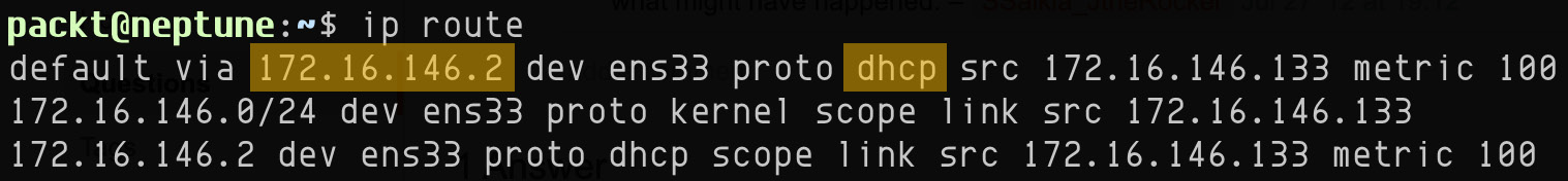
Figure 7.17 – Querying the IP route for DHCP information
The first line of the output provides the DHCP server (172.16.146.2).
Chapter 8, Configuring Linux Servers, will further go into the practical details of installing and configuring a DHCP server.
For more information on DHCP, please refer to RFC 2131 (https://tools.ietf.org/html/rfc2131).
DNS servers
A Domain Name Server (DNS), also known as a name server, provides a name-resolution mechanism by converting a hostname (such as wikipedia.org) to an IP address (such as 208.80.154.224). The name-resolution protocol is DNS, briefly described in the TCP/IP protocols section earlier in this chapter. In a DNS-managed TCP/IP network, computers and devices can also identify and communicate with each other by hostnames, not just IP addresses.
As a reasonable analogy, DNS very much resembles an address book. Hostnames are relatively easier to remember than IP addresses. Even in a local network, with only a few computers and devices connected, it would be rather difficult to identify (or memorize) any of the hosts by simply using their IP address. The internet relies on a globally distributed network of DNS servers.
There are four different types of DNS servers: recursive servers, root servers, top-level domain (TLD) servers, and authoritative servers. All these DNS server types work together to bring you the internet as you experience it in your browser.
A recursive DNS server is a resolver that helps you find the destination (IP) of a website you search for. When you do a lookup operation, a recursive DNS server is connected to different other DNS servers to find the IP address that you are looking for and return it to you in the form of a website. Recursive DNS lookups are faster, thanks to caching every query that they perform. In a recursive type of query, the DNS server calls itself and does the recursion while still sending the request to other DNS server to find the answer. There is also an iterative type of DNS lookup.
An iterative DNS lookup is done by every DNS server directly, without using caching. For example, in an iterative query, each DNS server responds with the address of another DNS server, until one of them has the matching IP address for the hostname in question and responds to the client. For more details on DNS server types, please check out the following Cloudflare learning solution: https://www.cloudflare.com/learning/dns/what-is-dns/.
DNS servers maintain (and possibly share) a collection of database files, also known as zone files—typically simple plain-text ASCII files, storing the name and IP address mapping. In Linux, one such DNS resolver file is /etc/resolv.conf.
To query the DNS server managing the local machine, we can query the /etc/resolv.conf file by running the following code:
cat /etc/resolv.conf | grep nameserver
The output yields the following code:

Figure 7.18 – Querying DNS server using /etc/resolv.conf
A simple way to query name-server data for an arbitrary host on a network is by using the nslookup tool. If you don't have the nslookup utility installed on your system, you may do so with the commands outlined next.
On Ubuntu/Debian, run the following command:
sudo apt-get install dnsutils
On CentOS, run this command:
sudo yum install bind-utils
For example, to query the name-server information for a computer named neptune.local in our local network, we run the following command:
nslookup neptune.local
The output is shown here:
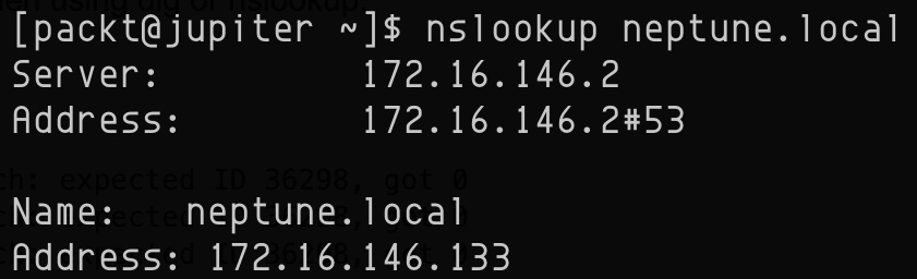
Figure 7.19 – Querying name-server information with nslookup
We can also use the nslookup tool interactively. For example, to query the name-server information for wikipedia.org, we can simply run the following command:
nslookup
Then, in the interactive prompt, we'll enter wikipedia.org: as illustrated here:
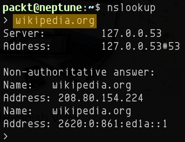
Figure 7.20 – Using the nslookup tool interactively
To exit the interactive shell mode, press Ctrl + C. Here's a brief explanation of the information shown in the preceding output:
- Server (Address): The loopback address (127.0.0.53) and port (53) of the DNS server running locally
- Name: The internet domain we're looking up (wikipedia.org)
- Address: The IPv4 (208.80.154.224) and IPv6 (2620:0:861:ed1a::1) address corresponding to the lookup domain (wikipedia.org)
nslookup is also capable of reverse DNS search when providing an IP address. The following command retrieves the name server (dns.google) corresponding to the IP address 8.8.8.8:
nslookup 8.8.8.8
The command yields the following output:
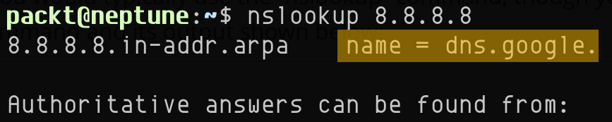
Figure 7.21 – Reverse DNS search with nslookup
For more information on the nslookup tool, you can refer to the nslookup system reference manual (man nslookup).
Alternatively, we can use the dig command-line utility. If you don't have the dig utility installed on your system, you can do so by installing the dnsutils package on Ubuntu/Debian or bind-utils on CentOS platforms. The related commands for installing the packages were shown previously with nslookup.
For example, the following command retrieves the name-server information for the computer named jupiter.local.localdomain in the local network:
dig jupiter.local.localdomain
This is the result (see the highlighted ANSWER SECTION):
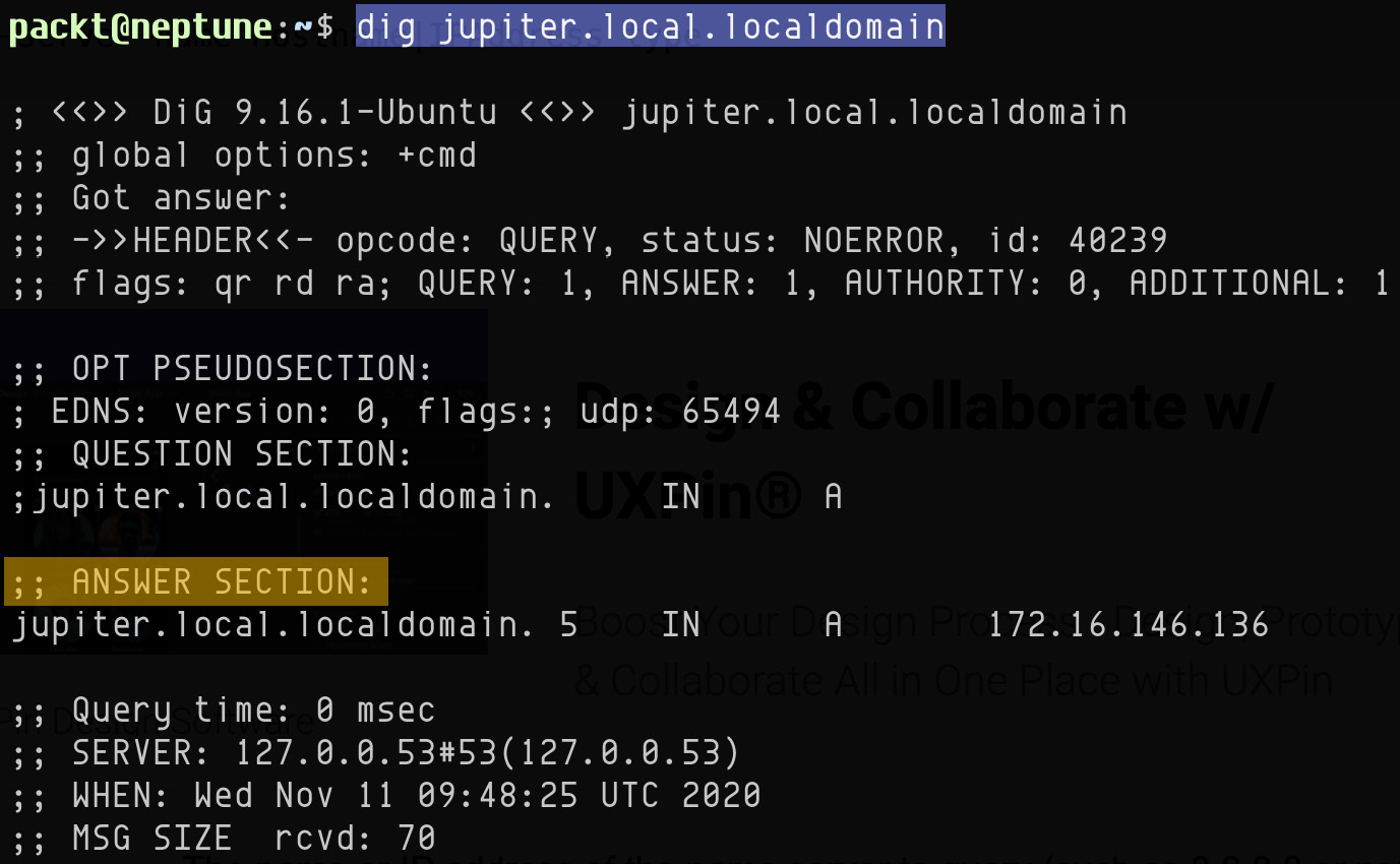
Figure 7.22 – Querying name-server information with dig
To perform a reverse DNS lookup with dig, we specify the -x option, followed by an IP address (for example, 8.8.4.4), as follows:
dig -x 8.8.4.4
The command yields the following output (see the highlighted ANSWER SECTION):

Figure 7.23 – Reverse DNS lookup with dig
For more information about the dig command-line utility, please refer to the related system manual (man dig).
The DNS protocol operates at the application layer (7) in the OSI model. The standard DNS service well-known port is 53.
Chapter 8, Configuring Linux Servers, will further go into the practical details of installing and configuring a DNS server. For more information on DNS, you can refer to RFC 1035 (https://www.ietf.org/rfc/rfc1035.txt).
The DHCP and DNS networking services are arguably the closest to the TCP/IP networking stack, while playing a crucial role when computers or devices are attached to a network. After all, without proper IP addressing and name resolution, there's no network communication.
Obviously, there's a lot more to distributed networking and related application servers than just strictly the pure network management stack performed by DNS and DHCP servers. In the following sections, we'll take a quick tour around some of the most relevant application servers running across distributed Linux systems.
Authentication servers
Standalone Linux systems typically use the default authentication mechanism, where user credentials are stored in the local filesystem (such as /etc/passwd, /etc/shadow). We explored the related user authentication internals in Chapter 4, Managing Users and Groups, earlier in this book. But as we extend the authentication boundary beyond the local machine—for example, accessing a file or email server—having the user credentials shared between the remote and localhosts would become a serious security issue.
Ideally, we should have a centralized authentication endpoint across the network, handled by a secure authentication server. User credentials should be validated using robust encryption mechanisms before users can access remote system resources.
Let's consider the secure access to a network share on an arbitrary file server. Suppose the access requires Active Directory (AD) user authentication. Creating the related mount (share) locally on a user's client machine will prompt for user credentials. The authentication request is made by the file server (on behalf of the client) to an authentication server. If the authentication succeeds, the server share becomes available to the client. The following diagram represents a simple remote authentication flow between a client and a server, using a Lightweight Directory Access Protocol (LDAP) authentication endpoint:

Figure 7.24 – Authentication workflow with LDAP
Examples of standard secure authentication platforms (available for Linux) include the following:
- Kerberos (https://en.wikipedia.org/wiki/Kerberos_(protocol))
- LDAP (https://en.wikipedia.org/wiki/Lightweight_Directory_Access_Protocol)
- Remote Authentication Dial-In User Service (RADIUS) (https://en.wikipedia.org/wiki/RADIUS)
- Diameter (https://en.wikipedia.org/wiki/Diameter_(protocol))
- Terminal Access Controller Access-Control System (TACACS+) (https://datatracker.ietf.org/doc/rfc8907/)
We'll go over the installation and configuration of a Linux LDAP authentication server (using OpenLDAP) in the Configuring an LDAP server section of Chapter 9, Securing Linux.
In this section, we illustrated the authentication workflow with an example using a file server. To remain on topic, let's look at network file-sharing services next.
File sharing
In common networking terms, file sharing represents a client machine's ability to mount and access a remote filesystem belonging to a server, as if it were local. Applications running on the client machine would access the shared files directly on the server. A text editor (for example) can load and modify a remote file, then save it back to the same remote location, all in a seamless and transparent operation. The underlying remoting process—the appearance of a remote filesystem acting as local—is made possible by file-sharing services and protocols.
For every file-sharing network protocol there is a corresponding client-server file-sharing platform. Although most network file servers (and clients) have cross-platform implementations, some operating system platforms are better suited for specific file-sharing protocols, as we'll see in the following subsections. Choosing between different file-server implementations and protocols is ultimately a matter of compatibility, security, and performance.
Here are some of the most common file-sharing protocols, with some brief descriptions for each.
SMB
The Server Message Block (SMB) protocol provides network discovery and file- and printer-sharing services. SMB also supports interprocess communication over a network. SMB is a relatively old protocol, developed by International Business Machines Corporation (IBM) in the 1980s. Eventually, Microsoft took over and made some considerable alterations to what became the current version through multiple revisions (SMB 1.0, 2.0, 2.1, 3.0, 3.0.2, and 3.1.1).
CIFS
The Common Internet File System (CIFS) protocol is a particular implementation of the SMB protocol. Due to the underlying protocol similarity, SMB clients would be able to communicate with CIFS servers, and vice versa. Though SMB and CIFS are idiomatically the same, their internal implementation of file locking, batch processing, and—ultimately—performance is quite different. Apart from legacy systems, CIFS is rarely used these days. SMB should always be preferred over CIFS, especially with the more recent revisions of SMB 2 or SMB 3.
Samba
As with CIFS, Samba is another implementation of the SMB protocol. Samba provides file- and print-sharing services for Windows clients on a variety of server platforms. In other words, Windows clients can seamlessly access directories, files, and printers on a Linux Samba server, just as if they were communicating with a Windows server.
As of version 4, Samba natively supports Microsoft AD and Windows NT domains. Essentially, a Linux Samba server can act as a domain controller on a Windows AD network. Consequently, user credentials on the Windows domain can transparently be used on the Linux server without being recreated, and then manually kept in sync with the AD users.
NFS
The Network File System (NFS) protocol was developed by Sun Microsystems and essentially operates on the same premise as SMB—accessing files over a network as if they were local. NFS is not compatible with CIFS or SMB, meaning that NFS clients cannot communicate directly to SMB servers, or vice versa.
Most of the time, NFS is the file-sharing protocol of choice within Linux networks. For mixed networking environments—such as Windows, Linux, and macOS interoperability—Samba and SMB are best suited for file sharing.
AFP
The Apple Filing Protocol (AFP) is a proprietary file-sharing protocol designed by Apple and exclusively operates in macOS network environments. We should note that besides AFP, macOS systems also support standard file-sharing protocols, such as SMB and NFS.
Some file-sharing protocols (such as SMB) also support print sharing and are used by print servers. Let's take a closer look at print sharing next.
Printer servers
A printer server (or print server) connects a printer to client machines (computers or mobile devices) on a network, using a printing protocol. Printing protocols are responsible for the following remote printing tasks over a network:
- Discovering printers or print servers
- Querying printer status
- Sending, receiving, queueing, or canceling print jobs
- Querying print job status
Common printing protocols include the following:
- Line Printer Daemon (LPD) protocol
- Generic protocols: SMB; TELNET
- Wireless printing protocols (such as AirPrint by Apple)
- Internet printing protocols (such as Google Cloud Print)
Among the generic printing protocols, SMB (also a file-sharing protocol) has been previously described in the File sharing section. The TELNET communication protocol is described in the Remote access section.
File- and printer-sharing services are mostly about sharing documents, digital or printed, between computers on a network. When it comes to exchanging documents, additional networking services come into play, such as file transfer and email services. Let's look at file transfer next.
File transfer
FTP is a standard network protocol for transferring files between computers on a network. FTP operates in a client-server environment, where an FTP client initiates a remote connection to an FTP server, and files are being transferred in either direction. FTP maintains a control connection and one or more data connections between the client and the server. The control connection is generally established on the FTP server's port 21, and it's used for exchanging commands between the client and the server. Data connections are exclusively used for data transfer and are negotiated between client and server (through the control connection). Data connections usually involve ephemeral ports for inbound traffic, and they only stay open during the actual data transfer, closing immediately after the transfer completes.
FTP negotiates data connections in one of the following two modes:
- Active mode—The FTP client sends a PORT command to the FTP server, signaling that the client actively provides the inbound port number for data connections.
- Passive mode—The FTP client sends a PASV command to the FTP server, indicating that the client passively awaits the server to supply the port number for inbound data connections.
FTP is a relatively "messy" protocol when it comes to firewall configurations, due to the dynamic nature of the data connections involved. The control connection port is usually well known (such as port 21 for insecure FTP) but data connections are originated on a different port (usually 20) on either side, while on the receiving end the inbound sockets are opened within a preconfigured ephemeral range (1024 – 65535).
FTP is most often implemented in a secure fashion through either of the following approaches:
- FTP over SSL (FTPS)—SSL/TLS-encrypted FTP connection. The default FTPS control connection port is 990.
- SSH File Transfer Protocol (SFTP)—FTP over SSH. The default SFTP control connection port is 22. For more information on the SSH protocol and client-server connectivity, refer to SSH in the Remote access section, later in this chapter.
Chapter 9, Securing Linux, looks closely at the practical implementation of a Linux FTP server.
Next, we'll look at mail servers and the underlying email exchange protocols.
Mail servers
A mail server (or email server) is responsible for email delivery over a network. A mail server can either exchange emails between clients (users) on the same network (domain)—within a company or organization—or deliver emails to other mail servers, possibly beyond the local network, such as the internet.
An email exchange usually involves the following actors:
- An email client application (such as Outlook or Gmail)
- One or more mail servers (Exchange; Gmail server)
- The recipients involved in the email exchange—a sender and one or more receivers
- An email protocol controlling the communication between the email client and the mail servers
The most used email protocols are POP3, IMAP, and SMTP. Let's take a closer look at each of these protocols.
POP3
POP version 3 (POP3) is a standard email protocol for receiving and downloading emails from a remote mail server to a local email client. With POP3, emails are available for reading offline. After download, emails are usually removed from the POP3 server, thus saving up space. Modern-day POP3 mail client-server implementations (Gmail; Outlook) also have the option of keeping email copies on the server. Persisting emails on the POP3 server becomes very important when users access emails from multiple locations (client applications).
The default POP3 ports are outlined here:
- 110—for insecure (non-encrypted) POP3 connections
- 995—for secure POP3 using SSL/TLS encryption
POP3 is a relatively old email protocol, not always suitable for modern-day email communications. When users access their emails from multiple devices, IMAP is a better choice. Let's look at the IMAP email protocol next.
IMAP
IMAP is a standard email protocol for accessing emails on a remote IMAP mail server. With IMAP, emails are always retained on the mail server, while a copy of the emails is available for IMAP clients. A user can access the emails on multiple devices, each with their IMAP client application.
The default IMAP ports are outlined here:
- 143—for insecure (non-encrypted) IMAP connections
- 993—for secure IMAP using SSL/TLS encryption
Both POP3 and IMAP are standard protocols for receiving emails. To send emails, SMTP comes into play. Let's take a look at the SMTP email protocol next.
SMTP
SMTP is a standard email protocol for sending emails over a network or the internet.
The default SMTP ports are outlined here:
- 25—for insecure (non-encrypted) SMTP connections
- 465 or 587—for secure SMTP using SSL/TLS encryption
When using or implementing any of the standard email protocols described in this section, it is always recommended to use the corresponding secure implementation with the most up-to-date TLS encryption, if possible. POP3, IMAP, and SMTP also support user authentication, an added layer of security—also recommended in commercial or enterprise-grade environments.
To get an idea about how the SMTP protocol operates, let's go through some of the initial steps for initiating a SMTP handshake with Google's Gmail SMTP server.
We start by connecting to the Gmail SMTP server, using a secure (TLS) connection via the openssl command, as follows:
openssl s_client -starttls smtp -connect smtp.gmail.com:587
We invoked the openssl command, simulating a client (s_client), starting a TLS SMTP connection (-starttls smtp), and connecting to the remote Gmail SMTP server on port 587 (-connect smtp.gmail.com:587).
The Gmail SMTP server responds with a relatively long TLS handshake block, ending with the following:
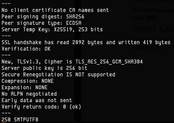
Figure 7.25 – Initial TLS handshake with a Gmail SMTP server
Next, we initiate the SMTP communication with a HELO command (spelled precisely as such). Google expects the following HELO greeting:
HELO hellogoogle
Another handshake follows, ending with 250 smtp.gmail.com at your service, as illustrated here:

Figure 7.26 – Gmail SMTP server is ready for communication
Next, the Gmail SMTP server requires authentication via the AUTH LOGIN SMTP command. We won't go into further details, but the key point to be made here is that the SMTP protocol follows a plaintext command sequence between the client and the server. It's very important to adopt a secure (encrypted) SMTP communication channel, using TLS. The same applies to any of the other email protocols (POP3; IMAP).
So far, we've covered several network services, some of them spanning multiple networks or even the internet. Network packets carry data and destination addresses within the payload, but there are also synchronization signals between the communication endpoints, mostly to discern between sending and receiving workflows. The synchronization of network packets is based on timestamps. Reliable network communications would not be possible without a highly accurate time-synchronization between network nodes. We'll look at the network time-keepers next.
NTP servers
NTP is a standard networking protocol for clock synchronization between computers on a network. NTP attempts to synchronize the system clock on participating computers within a few milliseconds of Coordinated Universal Time) (UTC)— the world's time reference.
The NTP protocol implementation usually assumes a client-server model. The NTP server acts as a time source on the network by either broadcasting or sending updated timestamp datagrams to clients. An NTP server continually adjusts its system clock according to well-known accurate time servers worldwide, using specialized algorithms to mitigate network latency.
A relatively easy way to check the NTP synchronization status on our Linux platform of choice is by using the ntpstat utility. ntpstat may not be installed by default on our system. On Ubuntu, we can install it with the following command:
sudo apt-get install ntpstat
On CentOS, we install ntpstat with the following command:
sudo yum install ntpstat
ntpstat requires an NTP server running locally. To query the NTP synchronization status, we run the following command:
ntpstat
This is the output:

Figure 7.27 – Querying NTP synchronization status with ntpstat
ntpstat provides the IP address of the NTP server the system is synchronized with (74.6.168.72), the synchronization margin (17 milliseconds), and the time-update polling interval (1024 s). To find out more about the NTP server, we can dig its IP address with the following code:
dig -x 74.6.168.72
And it looks like it's one of Yahoo's time servers (t1.time.gq1.yahoo.com), as we can see here:
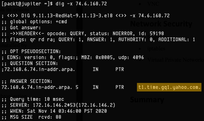
Figure 7.28 – Querying NTP synchronization status with ntpstat
The NTP client-server communication uses UDP as the transport protocol on port 123. Chapter 8, Configuring Linux Servers, has a dedicated section for installing and configuring an NTP server. For more information on NTP, you can refer to https://en.wikipedia.org/wiki/Network_Time_Protocol.
Our brief journey among networking servers and protocols is coming to an end here. Everyday Linux administration tasks often require some sort of remote access to a system. There are many ways to access and manage computers remotely. Our next section describes some of the most common remote-access facilities and related network protocols.
Remote access
Most Linux networking services provide a relatively limited remote management interface, with their management command-line interface (CLI) utilities predominantly operating locally on the same system where the service runs. Consequently, the related administrative tasks assume local terminal access. Direct console access to the system is sometimes not possible. This is when remote-access servers come into play to enable a virtual terminal login session with the remote machine.
Let's look at some of the most common remote-access services and applications next.
SSH
SSH is perhaps the most popular secure login protocol for remote access. SSH uses strong encryption, combined with user authentication mechanisms, for secure communication between a client and a server machine. SSH servers are relatively easy to install and configure, and Chapter 8, Configuring Linux Servers, has a dedicated section describing the related steps.
The default network port for SSH is 22.
SSH supports the following authentication types:
- Public-key authentication
- Host-based authentication
- Password authentication
- Keyboard-interactive authentication
The following sections provide brief descriptions of these SSH authentication forms.
Public-key authentication
Public-key (or SSH-key) authentication is arguably the most common type of SSH authentication.
Important note
This section will use the terms public-key and SSH-key interchangeably, mostly to reflect the related SSH authentication nomenclature in the Linux community.
The SSH-key authentication mechanism uses a certificate/key pair—a public key (certificate) and a private key. An SSH certificate/key pair is usually created with the ssh-keygen tool, using standard encryption algorithms such as the Rivest–Shamir–Adleman algorithm (RSA) or the Digital Signature Algorithm (DSA).
SSH public-key authentication supports either user-based authentication or host-based authentication models. The two models differ in the ownership of the certificate/key pairs involved. With client authentication, each user has its own certificate/key pair for SSH access. On the other hand, host authentication involves a single certificate/key pair per system (host).
Both SSH-key authentication models are illustrated and explained in the following sections. The basic SSH handshake and authentication workflows are the same for both models. First, the SSH client generates a secure certificate/key pair and shares its public key with the SSH server. This is a one-time operation for enabling the public-key authentication.
When a client initiates the SSH handshake, the server asks for the client's public key and verifies it against its allowed public keys. If there's a match, the SSH handshake succeeds, the server shares its public key with the client, and the SSH session is established.
Further client-server communication follows standard encryption/decryption workflows. The client encrypts the data with its private key, while the server decrypts the data with the client's public key. When responding to the client, the server encrypts the data with its own private key, and the client decrypts the data with the server's public key.
SSH public-key authentication is also known as passwordless authentication, and it's frequently used in automation scripts where commands are executed over multiple remote SSH connections without prompting for a password.
Let's take a closer look at the user-based and host-based public-key authentication mechanisms next.
User-based key authentication
User-based authentication is the most common SSH public-key authentication mechanism. According to this model, every user connecting to a remote SSH server has its own SSH key. Multiple user accounts on the same host (or domain) would have different SSH keys, each with its own access to the remote SSH server, as suggested in the following diagram:

Figure 7.29 – User-based key authentication
A somewhat similar approach to user-based SSH key authentication is the host-based authentication mechanism, described next.
Host-based key authentication
Host-based authentication is another form of SSH public-key authentication and involves a single SSH key per system (host) connecting to a remote SSH server, as illustrated in the following diagram:
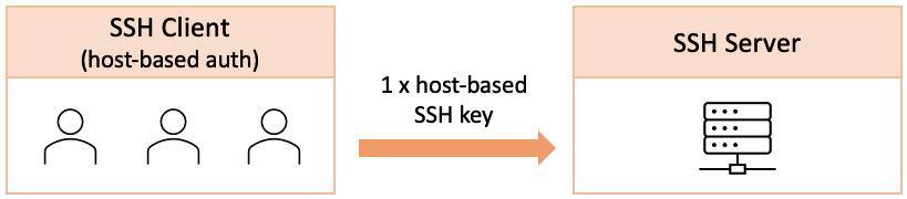
Figure 7.30 – Host-based key authentication
With host-based authentication, the underlying SSH key can only authenticate SSH sessions that originated from a single client host. Host-based authentication allows multiple users to connect from the same host to a remote SSH server. If a user attempts to use a host-based SSH key from a different machine than the one allowed by the SSH server, access would be denied.
Sometimes, a mix of the two public-key authentications is used—user- and host-based authentication—an approach that provides an increased security level to SSH access.
When security is not critical, simpler SSH authentication mechanisms could be more suitable. Password authentication is one such mechanism.
Password authentication
Password authentication requires a simple set of credentials from the SSH client, as a username and password. The SSH server validates the user credentials, either based on the local user accounts (in /etc/passwd) or select user accounts defined in the SSH server configuration (/etc/ssh/sshd_config). The SSH server configuration described in Chapter 8, Configuring Linux Servers, further elaborates on this subject.
Besides local authentication, SSH can also leverage remote authentication methods such as Kerberos, LDAP, RADIUS, and so on. In such cases, the SSH server delegates the user authentication to a remote authentication server, as described in the Authentication servers section earlier in this chapter.
Password authentication requires either user interaction or some automated way to provide the required credentials. Another similar authentication mechanism is keyboard-interactive authentication, described next.
Keyboard-interactive authentication
Keyboard-interactive authentication is based on a dialog of multiple challenge-response sequences between the SSH client (user) and the SSH server. The dialog is a plain-text exchange of questions and answers, where the server may prompt the user for any number of challenges. In some respect, password authentication is a single-challenge interactive authentication mechanism.
The interactive connotation of this authentication method could lead us into thinking that user interaction would be mandatory for the related implementation. Not really. As a matter of fact, keyboard-interactive authentication could also serve implementations of authentication mechanisms based on custom protocols, where the underlying message exchange would be modeled as an authentication protocol.
Before moving on to other remote access protocols, we should again call out the wide use of SSH due to its security, versatility, and performance. But SSH connectivity may not always be possible or adequate in specific scenarios. In such cases, TELNET may come to the rescue. Let's take a look at it next.
TELNET
TELNET is an application-layer protocol for bidirectional network communication using a plain-text CLI with a remote host. Historically, TELNET was among the first remote-connection protocols, but it always lacked a secure implementation. SSH eventually became the standard way to log in from one computer to another, yet TELNET has its own advantages over SSH when it comes to troubleshooting various application-layer protocols, such as web- or email-server communication.
Let's look at an example to get a sense of how TELNET works. We'll be simulating a simple HTTP request/response connecting to an Apache web server using TELNET. The general syntax of TELNET is shown here:
telnet HOST PORT
In our case, Apache runs on the jupiter.local host and port 80, as shown here:
telnet jupiter.local 80
We get the following response:
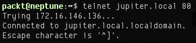
Figure 7.31 – Connecting with TELNET to a remote web server
Next, we initiate a web communication following the HTTP/1.1 protocol by typing the following command:
GET / HTTP/1.1
The HTTP/1.1 protocol requires a mandatory Host HTTP header, so we continue with the following code:
Host: localhost
After each of the preceding lines, we hit Enter (new line), and after the Host header, we hit Enter twice. The Apache web server responds as follows:

Figure 7.32 – HTTP request/response with TELNET
We truncated the response for brevity. The TELNET session we just ran shows the interactive step-by-step HTTP communication between a web client—our local terminal window—and a remote Apache web server (jupiter.local).
TELNET and SSH are command-line-driven remote-access interfaces. There are cases when a direct desktop connection is needed to a remote machine through a graphical user interface (GUI). We'll look at desktop sharing next.
VNC
Virtual Network Computing (VNC) is a desktop-sharing platform that allows users to access and control a remote computer's GUI. VNC is a cross-platform client-server application. A VNC server running on a Linux machine, for example, allows desktop access to multiple VNC clients running on Windows or macOS systems. The VNC network communication uses the Remote Framebuffer (RFB) protocol, defined by RFC 6143.
Setting up a VNC server is relatively simple. VNC assumes the presence of a graphical desktop system. You can refer to the Installing Linux graphical user interfaces section in Chapter 1, Installing Linux, to set up a GNOME or K Desktop Environment (KDE) desktop in Linux. Let's take an RHEL/CentOS 8 system with a GNOME desktop and configure VNC. We start by installing a VNC server, as follows:
sudo dnf install tigervnc-server tigervnc-server-module -y
Next, we create a VNC password for the current user, like this:
vncpasswd
The vncpasswd utility prompts for a password and asks if we want to use VNC in view-only mode. We choose full-control access. This is the output of the vncpasswd command:

Figure 7.33 – Setting up the VNC password
In the following step, we specify GNOME as the VNC desktop of our choice by running the following code:
printf 'gnome-session & gnome-terminal &' > ~/.vnc/xstartup
The ~/.vnc/xstartup file stores the current VNC configuration. Optionally, we can enable clipboard sharing with VNC, between the client and the server, with the following line added to the ~/.vnc/xstartup file:
vncconfig -iconic &
Here's the final content of the ~/.vnc/xstartup file:
gnome-session &
gnome-terminal &
vncconfig -iconic &
We are now ready to start the VNC server, so we run the following command:
vncserver -geometry 1920x1080
In the vncserver command, we specified a screen resolution for the VNC sessions (1920x1080). The command yields the following output:
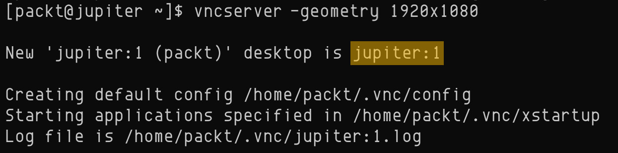
Figure 7.34 – Starting the VNC server
In the vncserver command's output, we should note the VNC desktop ID (jupiter:1). This ID will be used as the VNC client hostname. The default network port range for the VNC server starts with 5901. Multiple VNC clients connect to incremental ports.
Using a VNC client application—such as VNC Viewer (by RealVNC) on Mac OS X—we can now remotely access our CentOS 8 Linux machine, as shown in the following screenshot:

Figure 7.35 – Using a VNC client
For simplicity and space considerations, we described a relatively raw and straightforward way of running VNC. Obviously, we could be more creative about controlling the lifetime of the VNC process. The complementary source code of this chapter shows such a script.
This concludes our section about networking services and protocols. We tried to cover the most common concepts about general-purpose network servers and applications, mostly operating in a client-server or distributed fashion. With each network server, we described the related network protocols and some of the internal aspects involved. Chapter 8, Configuring Linux Servers, and Chapter 9, Securing Linux, will showcase practical implementations for some of these network servers.
In the next section, our focus turns to network-security internals.
Understanding network security
Network security represents the processes, actions, and policies to prevent, monitor, and protect unauthorized access into computer networks. Network security paradigms span a vast array of technologies, tools, and practices. Here are a few important ones:
- Access control—Selectively restricting access based on user authentication and authorization mechanisms. Examples of access control include users, groups, and permissions. Some of the related concepts have been covered in Chapter 4, Managing Users and Groups.
- Application security—Securing and protecting server and end-user applications (email, web, and mobile apps). Examples of application security include Security-Enhanced Linux (SELinux), strongly encrypted connections, antivirus, and anti-malware programs. We'll cover SELinux in Chapter 9, Securing Linux.
- Endpoint security—Securing and protecting servers and end-user devices (smartphones, laptops, and desktop PCs) on the network. Examples of endpoint security include firewalls and various intrusion-detection mechanisms. We'll look at firewalls in Chapter 9, Securing Linux.
- Network segmentation—Partitioning computer networks into smaller segments or virtual LANs (VLANs). This is not to be confused with subnetting, which is a logical division of networks through addressing.
- VPNs—Accessing corporate networks using a secure encrypted tunnel from public networks or the internet. We'll look at VPNs in Chapter 9, Securing Linux.
In everyday Linux administration, setting up a network security perimeter should always follow the paradigms enumerated previously, roughly in the order listed. Starting with access-control mechanisms and ending with VPNs, securing a network takes an inside-out approach, from local systems and networks, to firewalls, VLANs, and VPNs. The next section explores VPNs.
VPNs
A VPN is a networking technology that provides online security, privacy, and anonymity to users by creating a private network over a public internet connection. VPNs are generally used to accommodate the following scenarios:
- Establishing a secure encrypted connection between a device and a private or corporate network
- Enabling access to region-restricted websites (prevent geo-blocking)
- Shielding internet activity from prying eyes
VPNs essentially create a data tunnel within a network—usually the internet—to securely access network resources remotely, bypass internet censorship, mask IP addresses, and more.
Let's take a look at how VPNs work.
Working with VPNs
VPNs are based on a client-server architecture routing a client device's network communication through a VPN server. The VPN server provides an encrypted communication tunnel with the client device, acting as an intermediary of sorts between the client and the internet, or a private (or corporate) network. VPN implementations typically use OSI Layer 2 and 3 network extensions with SSL/TLS protocols.
Commercial or enterprise-grade VPN solutions usually ship a proprietary VPN client app that users install on their computers and mobile devices. The VPN client is configured to use specific VPN endpoints provisioned by the app. Notable commercial VPN products include ExpressVPN, NordVPN, Surfshark, Norton Secure VPN, and IPVanish.
Most operating systems have integrated client support for general-purpose VPN. In the following sections, we describe the configuration of a VPN environment using Open VPN —an open source VPN solution.
Setting up OpenVPN
In this section, we'll guide you through the process of setting up OpenVPN on Ubuntu Server 20.04 Long-Term Support (LTS). We'll use a virtual private server (VPS) for our VPN endpoint, featuring a public network interface. The main reason for a VPS environment hosted in a public cloud (such as Amazon Web Services (AWS)/Elastic Compute Cloud (EC2), DigitalOcean, Linode, and so on) is the commodity of having a directly accessible public IP address over the internet. Alternatively, we could use an arbitrary host within a private network, with the required network address translation (NAT) configuration settings in the firewall or router, to make it accessible from the public internet.
A quick way to set up a VPN is by using an open source utility assisting with the OpenVPN configuration, available at https://git.io/vpn. The following procedure will help you set up a VPN in a matter of minutes. Here are the steps we'll be following:
- Identifying the network interface for VPN connections
- Downloading and running the VPN installer script
- Connecting to the VPN using a Linux client
Let's start with the first step.
Identifying the VPN network interface
A typical host—acting as VPN server—has either of the following network configurations:
- A private static IP address behind a NAT/router/firewall with a public IP address. Examples include AWS/EC2 instances or home network computers behind a general-purpose router.
- A public static IP address routable from the internet. Examples of such include VPS instances by DigitalOcean, Linode, and others.
In our example, we use a DigitalOcean VPS instance. Let's look at our network interfaces available on the system, as follows:
ip addr
This is the output of the preceding command:

Figure 7.36 – Identifying network interfaces
In our case, the eth0 interface has a publicly facing IP address of 138.68.19.158 with a corresponding local (internal) IP address of 10.46.0.5. These network addresses are relevant in our next step for configuring the VPN, using the VPN installer script.
Configuring VPN
We start by making sure our system is up to date by running the following commands:
sudo apt-get update
sudo apt-get upgrade
Next, we download and run the VPN installer script with the following command:
wget https://git.io/vpn -O vpnsetup && bash vpnsetup
We chose the arbitrary name of vpnsetup for the installer script. The script provides step-by-step guided assistance, as can be seen in the following screenshot:
Figure 7.37 – Running the VPN installer
We highlighted the relevant choices, as follows:
- 138.68.19.158—The IP address of the network interface we dedicate for VPN connections
- UDP—The recommended OpenVPN protocol
- 1194—The VPN connection port
- Current system resolvers—The default DNS subsystem on the host
- client—The name of the VPN client instances
Upon successfully running the VPN installer, we can verify the running status of the OpenVPN server with the following command:
sudo systemctl status [email protected]
We should get the following active(running) status:
Figure 7.38 – Querying the OpenVPN server status
The script also generates a default OpenVPN client profile as a file named according to the name of the VPN client chosen in the final step of the VPN installer script (that is, client). In our case, the file is ~/client.ovpn, as we can see here:
cat ~/client.ovpn
Here's an excerpt from it:

Figure 7.39 – The OpenVPN client profile (.ovpn file)
The OpenVPN client profile is shared with a specific VPN client, as we'll see next. We can generate multiple such distinct client profiles by running the VPN installer script multiple times. Since we downloaded the VPN installer script, we can also invoke it locally. We need to make the script executable, first by running the following commands:
chmod a+x ./vpnsetup
./vpnsetup
Subsequent runs of the script provide us with the following options:
Figure 7.40 – A subsequent invocation of the VPN installer
Choosing option 1) will generate a new client profile. The other options are also obvious, according to their descriptions. Client profiles are shared exclusively with the OpenVPN clients using our VPN.
Next, let's take a look at how to configure VPN clients using our OpenVPN server. OpenVPN clients are supported on all major operating system platforms. In the following examples, we showcase OpenVPN clients running on Linux and Android platforms.
Configuring a Linux OpenVPN client
The instructions in this section will help you configure OpenVPN client connectivity on Ubuntu and CentOS platforms. Using your client platform of choice, start by installing the openvpn client package, as follows:
- On Ubuntu, run the following command:
sudo apt-get install -y openvpn
- On CentOS, run the following command:
sudo yum install -y openvpn
Next, we copy the OpenVPN client profile (generated in the Configuring VPN section) to /etc/openvpn/client/client.conf. We assume the client.ovpn profile has been copied over to the client machine (such as in /home/packt/client.ovpn), and run the following code:
sudo cp /home/packt/client.ovpn /etc/openvpn/client/client.conf
At this point, we can immediately test the VPN client connectivity by running the following code:
sudo openvpn --client --config /etc/openvpn/client/client.conf
Here's an excerpt from the output of a successful VPN connection:

Figure 7.41 – Testing the OpenVPN client connectivity
You may exit with Ctrl + C from the preceding process. To enable the OpenVPN client on the system, we start the related daemon, as follows:
sudo systemctl start openvpn-client@client
The @client invocation of the openvpn-client daemon denotes the related OpenVPN client configuration file (in /etc/openvpn/client/client.conf). If the configuration file is named differently, we should adjust the preceding command accordingly.
The status of the OpenVPN client should show as active, as can be seen in the following screenshot:
Figure 7.42 – Querying the OpenVPN client status
After successfully establishing the VPN client connection, your client machine's public IP address should match the VPN server's public IP (138.68.19.158). You can check this by running the following command:
dig TXT +short o-o.myaddr.l.google.com @ns1.google.com
This is the output of the preceding command:
Figure 7.43 – Retrieving the public IP address of the client machine
To stop VPN client connectivity, we run the following command:
sudo systemctl stop openvpn-client@client
We can also configure OpenVPN clients on a variety of other operating system platforms. Let's look at a mobile platform next.
Configuring an Android OpenVPN client
First, install the OpenVPN Connect app from the Android App store. Next, open the app and import the OpenVPN client profile. We generated the client profile previously, as described in the Configuring VPN section. You have a couple of options to import the profile, either by specifying the Uniform Resource Locator (URL) of the file (such as a Google Drive direct link, OneDrive, or Dropbox) or just pointing to the downloaded file, if the mobile platform supports access to downloads.
The process is illustrated in the following screenshot:
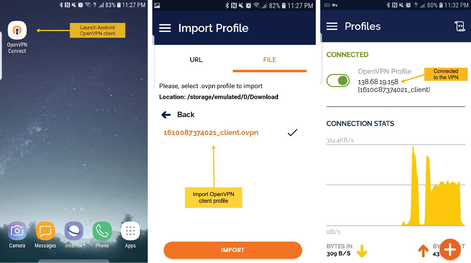
Figure 7.44 – Using the Android OpenVPN client app
After importing the OpenVPN client profile, you can connect to the VPN. The following illustrations suggest the steps described previously. Upon connecting to the VPN, our mobile device's public IP address becomes 138.68.19.158—the VPN server's IP address.
For more information about the OpenVPN project and related product downloads, please visit https://openvpn.net/download-open-vpn/.
Summary
This chapter represents a relatively condensed view of basic Linux networking principles. We have learned about network communication layers and protocols, IP addressing schemes, TCP/IP configurations, well-known network application servers, and VPN. A good grasp of networking paradigms will give Linux administrators a more comprehensive view of the distributed systems and underlying communication between the application endpoints involved.
Some of the theoretical aspects covered in this chapter are taken for a practical spin in Chapter 8, Configuring Linux Servers, focusing on real-world implementations of network servers. Chapter 9, Securing Linux, will further explore network security internals and practical Linux firewalls. Everything we have learned so far will serve as a good foundation for the assimilation of these upcoming chapters.
Questions
Here's a quick quiz to outline and attest some of the essential concepts covered in this chapter:
- How does the OSI model compare to the TCP/IP model?
- Think of a couple of TCP/IP protocols and try to see where and how they operate in some of the network administration tasks or applications you are familiar with.
- At what networking layer does the HTTP protocol operate? How about DNS?
- What is the network class for IP address 192.168.0.1?
- What is the network prefix corresponding to network mask 255.255.0.0?
- How do you configure a static IP address using the nmcli utility?
- How do you change the hostname of a Linux machine?
- What is the difference between the POP3 and IMAP email protocols?
- How does SSH host-based authentication differ from user-based SSH key authentication?
- What is the difference between SSH and TELNET?