
In some cases, a single broadcast domain is formed by combining two or more interfaces. Two ports on your pfSense router act as if they are on the same switch, except that the firewall rules are used to control the traffic between the interfaces. This can be achieved using bridging, but you need to be careful to avoid loops when employing bridging As mentioned earlier, the primary means of preventing looping on bridges is to use the STP, which is employed by managed switches and routers (including pfSense).
It should be noted that, in the current version of pfSense, bridged interfaces are treated no differently than non-bridged interfaces. Therefore, firewall rules are applied to each interface that is a member of the bridge on an inbound basis. Older versions of pfSense had filtering turned off on bridges by default, and it had to be enabled to work. In the current version of pfSense, there is no way to selectively disable filtering on bridges; the only way to do so is to use the Disable Firewall checkbox in System | Advanced; this disables all packet filtering.
Bridging two internal interfaces in pfSense is fairly easy, but there are some issues that you need to address:
- One interface will have an IP address (the main interface) and one will have no IP address (the bridged interface)
- You need to make sure that the DHCP server is running only on the main interface and not on the one being bridged
- In order to allow DHCP traffic on the interface, you need to create a firewall rule on the bridged interface
To bridge interfaces in pfSense, navigate to Interfaces | (assign) and click on the Bridges tab. On this tab a table displaying all configured bridges will be present. To add a new bridge, click on the Add button below the table and to the right.
On the Bridge configuration page, you must select at least two interfaces in the Member Interfaces listbox. These are the interfaces that will be bridged. You may also enter a brief non-parsed description in the Description edit box.
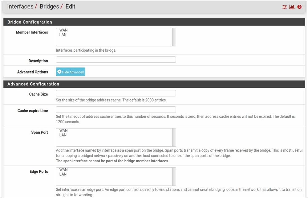
The Bridges configuration page, showing some advanced settings.
Setting up a bridge can be as simple as selecting the interfaces, but clicking on the Show Advanced button reveals a number of advanced options, many of them pertaining to spanning trees. The Cache size edit box allows you to set the size of the bridge address cache. The default size is 2000 entries. The Cache expire time edit box allows you to set the timeout (in seconds) of address cache entries. The address cache entries will not be expired if this field is set to zero. The default expire time is 1200 seconds.
The next setting is the Span Port listbox. If an interface is set as a span port, then that interface will transmit a copy of each frame received by the bridge. This can be useful for monitoring network traffic. Note that the span interface cannot be one of the bridge members.
Next is the Edge Ports listbox. An edge port is a port that is only connected to one bridge. As such, it cannot create bridging loops in the network, and thus can transition straight to the forwarding state. The Auto Edge Ports listbox will cause the selected ports to automatically detect the edge status, which is the default for bridge interfaces.
The PTP Ports listbox sets the selected interfaces as point-to-point links, which is necessary if the interface is to make a straight transition to forwarding. The Auto PTP Ports listbox allows you to select interfaces for which pfSense will automatically detect the point-to-point status by checking the full duplex link status. This is the default for bridged interfaces.
The Sticky Ports listbox allows you to mark an interface as sticky, which causes dynamically learned address entries from the interface to be treated as static once they enter the cache. These entries are never aged out of the cache or replaced, even if the learned address is seen on a different interface. Finally, the Private Ports listbox allows you to mark selected interfaces as private interfaces; these interfaces will not forward traffic to any other interface that is also private.
If you are going to use a spanning tree, you have to choose which STP to use. pfSense currently supports two protocols:
- STP: As described earlier, the original STP creates a spanning tree within a network of layer 2 bridges and disables links that are not part of the spanning tree, leaving a single path between any two nodes on the tree. This protocol was eventually standardized by the IEEE as 802.1D. STP is a relatively simple protocol, but it can take close to a minute for it to respond to a topology change.
- Rapid Spanning Tree Protocol (RSTP): Standardized by the IEEE as 802.1w, RSTP reduces the convergence time for responding to a topology change to a matter of seconds, but at the price of some added complexity. STP has three bridge port roles – root, designated, and disabled – and RSTP adds two (alternate, which provides an alternate path to the root bridge, and backup, which is a backup or redundant path to a segment) for a total of five bridge port roles. This, and the fact that the number of switch port states is reduced to three (discarding, learning, and forwarding), helps decrease the convergence time.
You can set the STP options by scrolling down to the RSTP/STP section. Right above this section is the Enable RSTP/STP checkbox, which you must check to enable these protocols. Next is the Protocol drop-down box, where you can select the protocol. The STP Interfaces listbox allows you to select the interfaces on which STP/RSTP is enabled. The Valid time field allows you to specify how long a spanning tree configuration will be valid, while in the Forward time field you can specify a delay for forwarding packets when RSTP or STP is enabled. The defaults for Valid time and Forward time are 20 seconds and 30 seconds respectively. The Hello Time field allows you to set the time between broadcasting STP configuration messages (when STP mode is invoked). The Priority field is where you can enter the bridge priority, and the Hold count field represents the number of packets that will be sent before rate limiting is invoked.
The final series of edit boxes sets the spanning tree priority for each of the interfaces. You can set them to anything from 0 to 240 (in increments of 16); the default is 128. You can also set the path cost for each interface. By default, the path cost is calculated from the link speed. However, you can manually set it to anything from 1 to 200000000. Set it to 0 to change it back to the default behavior. When you are done making changes, click on the Save button and, from the main Bridges page, click on Apply Changes.
If you haven't done so already, you should disable DNS on the bridged interface. You can do this by navigating to Services | DHCP Server (or DHCPv6 Server/RA), clicking on the tab for the bridged interface, making sure the Enable checkbox is unchecked, and clicking on the Save button. This will ensure that DHCP continues to function properly.
You also need to create a firewall rule on the bridged interface to allow DHCP traffic. To do that, navigate to Firewall | Rules, click on the tab of the bridged interface, and click the Add button. Normally, the Source field is set to a network or IP address. DHCP is a special case, because a client does not yet have an IP address. Thus, you must set the Source to 0.0.0.0 (choose Single host or alias in the Source drop-down box). Set the source port to 68. In the Destination field, set the destination to 255.255.255.255 and set the destination port to 67. In the Protocol drop-down box, select UDP. Make sure the Action drop-down box is set to Allow, click on the Save button, then click on Apply Changes on the main Firewall page. Make sure the new rule is at the top of the list of rules for the interface. Once this rule has been added, clients in the bridged segment should be able to receive DHCP leases.
Bridged interfaces behave somewhat differently from non-bridged interfaces, and for that reason you may find there are some things that cannot be done with bridges. In other cases, you may have to make modifications in order to get a pfSense feature to work with bridging.
A captive portal requires an IP on each interface on which it is active; this IP address is used to serve the portal contents. But bridged interfaces do not have an IP address. Therefore, captive portals do not work with bridging.
Another situation where bridged interfaces can be problematic is with multi-WAN setups. This is because the nodes on the bridged interfaces often have a different gateway than pfSense, and the router that is the default gateway for these nodes is the only device that can direct traffic from these nodes. However, multi-WAN can still work on a pfSense firewall in the following situations:
- Nodes on the bridged interfaces have pfSense as their default firewall
- Multi-WAN is being used only on non-bridged interfaces
CARP also does not work well with bridging, and we can illustrate why it doesn't work well with a diagram. A standard CARP setup with two firewalls, one master and one backup, will have both firewalls connected to the switch for each internal interface (for example, LAN and OPT1). This is acceptable, as there is still only one path to each of the switches for a node. The two network segments are essentially merged into a single larger network when they are bridged. A loop is formed when two paths are created between the switches for each interface. For example, in a CARP setup without looping, a node on LAN has one path to a node on OPT1 – through the master firewall. If the interfaces are bridged, however, there will be two paths to OPT1 – the bridge on the master firewall and the bridge on the backup firewall.
If the interface switch is a managed switch, we can handle it better by implementing STP or RSTP on the managed switch. Unmanaged switches, however, have no way of preventing looping, and looping can essentially crash a network.
There is another way of using bridged interfaces with CARP, although it is somewhat inelegant. It entails the following steps:
- Configure your master and backup firewalls as you would with any CARP deployment, taking care to ensure the interface assignments are identical on all firewalls. This should carry over to the bridged interfaces; the bridges should be copied so they are also identical.
- If you are using managed switches, use STP/RSTP to ensure the port connecting the switch to the master firewall has priority over the port connecting the switch to the backup firewall. When you are done configuring the ports, confirm that the master firewall's port is forwarding traffic and the backup firewall's port is blocking traffic.
- Another possible method is to use a script to ensure that a bridge on the firewall is up only if the firewall is designated as MASTER. This can be done by running the
ifconfigcommand on thecarp0interface, and checking the content of the command's output using a command such asgrep. Once you have installed the script, you can run the script automatically using the cron daemon. You will likely want to run the script fairly often – for example, every 60 seconds – to ensure that, when there is a failover, it is as smooth as possible. - Yet another possible method is to use
devdto catch when the actual CARP state transition happens. You can edit/etc/devd.confon the master and backup firewalls so that the bridge (or bridges) is/are brought up and down whenever a CARP state transition is detected.
It is beyond the scope of this chapter to describe these procedures in detail. If you require to implement this solution on your network, you can find these methods described in a post at the official pfSense forum at http://forum.pfsense.org/index.php/topic,4984.0.html.
To provide an example of bridging, we'll use pfSense to bridge two interfaces – LAN and OPT1. We will also assume that there are downstream routers and, to prevent looping, we will run RSTP on the bridged interfaces. In this case, LAN1 will be the main interface and OPT1 will be the bridged interface. Assume that the LAN interface has an IP address of 172.16.1.1 and a subnet of 172.16.0.0, and that the DHCP server is running on LAN.
To begin, we navigate to Services | DHCP Server and disable DHCP on OPT1. To do this, we uncheck the Enable checkbox, and click on the Save button. Now we can create our bridge. To do so, we navigate to Interfaces | (assign) and click on the Bridges tab. We click on the Add button on that page to add a new bridge.
Since we are bridging LAN and OPT1, we select these two interfaces in the Member Interfaces listbox. We also enter a brief description in the Description edit box (for example LAN to OPT1 bridge). If all we wanted to do is create a simple bridge, we would be done with configuration, but we want to run RSTP on the bridged interfaces, so we click on the Show Advanced button and scroll down the page. We check the Enable RSTP checkbox, and then in the RSTP/STP section we leave the protocol in the Protocol dropdown set to RSTP. In the STP interfaces listbox, we select LAN and OPT1. Assume also that, in spanning tree calculations, we want the LAN port to be favored over OPT1, so we scroll down and set LAN Path cost to 1 and OPT1 to 1000. Once we are done setting these values, we click on the Save button and then click on Apply Changes on the main Bridges page.
We have now configured the bridge, but we still must create a firewall rule on the OPT1 interface to allow for DHCP traffic. Thus, we navigate to Firewall | Rules and click on the OPT1 tab, then click on the Add button. On the Rules configuration page, we set Protocol to UDP. In the Source drop-down box, we select Single host or alias and type 0.0.0.0 in the corresponding edit box. We click on the Display Advanced button, and in the Source port range edit box, we enter 68. For Destination, we also select Single host or alias and type 255.255.255.255 in the corresponding edit box. In the Destination port range edit box, we enter 67. We enter a brief description (for example, Allow DHCP traffic), click on the Save button, and then click on the Apply Changes button on the main firewall rules page.
When we have confirmed that the newly created rule is at the top of the list of rules for the OPT1 interface, our configuration is complete. Clients connecting to OPT1 should now be able to receive an address on the 172.16.0.0 subnet from the DHCP server on LAN.