
Chapter 1
Mechatronics Systems Based on CAD/CAM 1
This chapter describes several mechatronics systems that use computer-aided design/computer-aided manufacturing (CAD/CAM) software. These mechatronics systems include: a five-axis NC machine tool with a tilting head, a three-axis NC machine tool with a rotary unit, articulated-type industrial robots with six degreesof-freedom (DOF), and a desktop Cartesian-type robot with high-position resolution.
1.1. Introduction
Computer-aided design (CAD) involves creating computer models defined by geometrical parameters. Computer-aided manufacturing (CAM) uses geometrical design data to control automated machinery. CAD/CAM use computer-based tools and simulation that greatly assist the integration of design and manufacture processes. The main-processor of CAM generates cutter location data called CL data that contain precise position and orientation components, when the linear approximation mode is selected in CAM parameters. Hence, to achieve efficient implementation, machine tools and robotics can display superior abilities and high-level functions using the generated CL data.
1.2. Five-axis NC machine tool with a tilting head
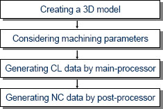
In this section, a three-dimensional (3D) machining system based on a five- axis NC machine tool with a tilting head is evaluated as a conventional system [NAG 96]. The five-axis NC machine tool is one of the most representative and popular machine tools in wood product manufacturing. The machining system consists of a 3D CAD/CAM with variable-axis function and a post-processor. Figure 1.1 shows the five-axis NC machine tool (HEIAN FF-151MC). The NC machine tool has a tilting head that can simultaneously incline and rotate. It should be noted, however, that corrected NC data are required to run the NC machine tool as a computer simulation. The post-process generally involves computing corrected NC data from CL data. Figure 1.2 shows the general process to calculate the corrected NC data for the five-axis NC machine tool.
Figure 1.1. Five-axis NC machine tool with a tilting head

Figure 1.2. Process to compute NC data for five-axis NC machine tool
Examples of paint roller models with a relief design are shown in Figure 1.3. First, the model of a relief design was drawn using a 3D CAD. Second, CAM parameters such as pick feed, path pattern (e.g. zigzag path), in/out tolerances, and so on are set according to the requirement of actual machining. The main-processor of CAM calculates cutter paths using the parameters. The cutter paths are called CL data. The i-th step CL(i) in CL data is composed of position vector p(i) = [x(i) y(i) z(i)]T and normal direction vector n(i) = [nx(i) ny(i) nz(i)]T which are given as follows:
Figure 1.3. Artistic paint roller models designed by 3D CAD

Finally, the post-processor generates corrected NC data for the five-axis NC machine tool with a tilting head, only by considering the tool length [NAG 96]. Figure 1.4 shows the main head with a tilting mechanism, which has a ball-end mill at the tip. The tool length L1 + L2 is defined as the distance from the center of swing to the tip of the ball-end mill, which should be measured in advance. The post-processor transforms the CL data into NC data for the five-axis NC machine tool as shown in Figure 1.1. The main head can incline and rotate within the range ±90 and ±180 degrees, respectively. The inclined and rotated axes are called the 4th(B) axis and 5th(C) axis, respectively. The i-th step in the corrected NC data is written by:
where b(i) and c(i) are the head angles of inclination and rotation, respectively. The CL data generated from the main-processor of CAM are composed of sequential points on the model’s surface. If the NC data are transformed from the CL data without considering the tool length and are given to the NC machine tool, then the center of swing directly follows the NC data. This would cause a serious and dangerous interference between the main head and the workpiece. On the contrary, if the center of swing follows the corrected NC data given by equations [1.3] and [1.4], the tip of the ball-end mill can desirably move along the model surface.
Figure 1.4. Definition of tool length in case of a tilting head

Recently, such a five-axis NC machine tool with a tilting head has become a center of attraction in wood product manufacturing. However, it has been recognized from machining experiments that the five-axis NC machine tool is not suitable for carving roller models as shown in Figure 1.3. Although high machining performance is expected to exceed the capability of standard NC machine tools, it has been hardly used for carving roller models yet. The main reason is that the roller models as shown in Figure 1.3 cannot be machined in a single path for the cutter, that is, models have to be machined using multiple paths for the cutter, requiring complicated cutter repositioning; thus, the 3D machining for artistic design paint rollers is complicated and time consuming. Furthermore, it is not easy to realize the modeling of a relief design on a cylindrical shape. To overcome these problems, a 3D machining system based on a three-axis NC machine tool with a rotary unit is discussed in the next section.
1.3. Three-axis NC machine tool with a rotary unit
1.3.1. Introduction
As described in the previous section, the wooden paint rollers have a cylindrical shape with an artistic design so that it is not easy to observe its elaborate carving even when the latest woodworking machinery such as a five-axis NC machine tool with a tilting head is used. Generally, metallic cylindrical parts are precisely processed by an expensive CNC turning center with milling capability. However, in the furniture manufacturing industry, three-axis NC machine tools and five-axis NC machine tools with a tilting head have been mainly used. Thus, a new woodworking machinery for wooden paint rollers should be designed by utilizing such existing NC machine tools and by considering the equipment cost. In this section, a three-axis NC machine tool with a rotary unit and its post-processor are proposed to efficiently produce artistic wooden paint rollers of many kinds of designs. The proposed machining system is used easily and at low cost by only adding a compact rotary unit on a conventional three-axis NC machine tool. The post-processor provides two effective functions. One is a transformation technique from CL data without feedrate values to NC data, mapping the y-directional pick feeds to rotational angles of the rotary unit. The post-processor allows a well-known three-axis NC machine tool to easily transcribe a relief design from a flat model to a cylindrical model. The other function is an elaborate addition of feedrate codes according to the curvature of each design to protect the cylindrical surface from an undesirable edge chipping. The post-processor generates safe feedrate values using a simple fuzzy reasoning method while checking edges and curvatures in a relief design, and appends them into NC data. The post-processed NC data mildly act on the fragile edges of wooden paint rollers [NAG 09].
1.3.2. Post-processor for a three-axis NC machine tool with a rotary unit
Conventional paint rollers generally have no artistic designs or if they do, designs are limited to flat or simple patterns even if they have. As mentioned in the previous section, unfortunately, it is not easy to carve a relief design on a cylindrical workpiece even if the five-axis NC machine tool with a tilting head is used. First of all, we discuss the problem concerning 3D machining of wooden cylindrical shapes with a relief design. When the modeling of a roller is conducted using a 3D CAD, a base cylindrical shape is modeled in advance. Then a favorite relief design is drawn on the cylindrical model. However, the modeling of relief design on the cylindrical shape as shown in Figure 1.3 is a complicated task, even when high-end 3D CAD software is used. Next, it is not easy to realize its 3D machining using the five-axis NC machine tool with a tilting head, in which the NC data generated from CAM are composed of x-, y-, z-, b-, and c-directional components. Thus, to easily provide many kinds of paint rollers with a wide variety and low volume to home making industries, a machining system that can directly carve an artistic relief design on a cylindrical workpiece must be developed.
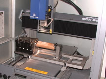
To cope with these problems, a new 3D machining system is considered based on a three-axis NC machine tool with a rotary unit, and a post-processor is proposed for the rotary unit. The post-processor allows conventional woodworking machinery as the three-axis NC machine tool to elaborately produce wooden paint rollers. An artistic design drawn on a flat model surface can easily be transcribed to a cylindrical model surface. In the remainder of this section, the system is described in detail. A three-axis NC machine tool with x-, y-, and z-axes must be first prepared to realize the proposed concept. As an example, an NC machine tool MDX-650A provided by Roland D.G. as shown in Figure 1.5 is used for experimentation. The NC machine tool is equipped with an auto tool changer ZAT-650 and a rotary unit ZCL-650A. The mechanical resolution of the rotary unit is about 0.0027 degrees. The NC machine tool has four DOF, that is, three translations and one rotation. This section addresses how to easily make a wooden paint roller with an artistic relief design. The most important point is that proper NC data for the NC machine tool with a rotary unit can be generated in one step. To meet this end, the post-processor generates the NC data that transcribe the design on a flat model to it on a cylindrical model. By applying the post-processed NC data, the NC machine tool can directly carve an artistic relief design on a cylindrical workpiece.
Figure 1.5. Three-axis NC machine tool MDX-650 with a rotary unit
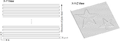
Next, we describe the feature of the post-processor. A desired relief design is first modeled on a flat base model. The CL data are then generated with a zigzag path as shown in Figure 1.6. In this case, the coordinate system should be set so that the pick-feed direction is parallel to the table slide direction of the NC machine tool, that is, y-direction. The proposed post-processor transforms the CL data without “FEDRAT/” statements into the corresponding NC data, mapping y-directional positions to rotational angles of the rotary unit. As can be seen from the components of the NC data, when the rotary unit is active, the table slide motion in y-direction is inactive. The post-processor first checks all steps in the CL data, and extracts the minimum value y_min and the maximum value y_max in y-direction. The angle a(i) for the rotary unit at the i-th step is easily calculated from equation [1.5]:
where y_length is the length in y-direction, which is obtained by y_max–y_min. The CL data p(i) = [x(i) y(i) z(i)]T at the i-th step is transformed into the NC data composed of [x(i) a(i) z(i)]T using equation [1.5]. The length in y-direction is transformed into the circumference of the roller model. The amount of the small angle a(i) depends on the ratio of y_length to y_pick. It is expected that the relief design shown in Figure 1.6 is desirably carved on the surface of a cylindrical workpiece. Thus, the proposed system provides a function that easily transcribes an artistic design from the surface on a flat model to a surface on a cylindrical wooden workpiece fixed to the rotary unit.
Figure 1.6. Generation of zigzag path
1.3.3. Experiment
In the previous section, a three-axis NC machine tool with a rotary unit and its post-processor were introduced to efficiently machine cylindrical wooden workpieces. The machined workpiece can be used as an artistic paint roller, which is very useful and convenient to directly transcribe a relief design to a wall just after painting. In this section, an actual machining experiment of a cylindrical wooden workpiece is conducted using the proposed system. Although up till now there have been few studies to investigate optimal machining conditions with respect to the machined curved surface of wood, Fujino et al. [FUJ 03] examined the influences of machining conditions such as feedrate and feed direction to the grain using two wood species, in which constant feedrate values under 2,000 mm/min were evaluated. The roughness of the machined surface was measured based on 3D profiles obtained by laser scanning, where the surface roughness was shown to be improved as the feedrate decreased. It is expected from the above result that the decrease of feedrate will be effective to suppress an undesirable edge chipping. Wooden materials are essentially brittle compared with metallic materials so that the increase of feedrate tends to bring out the edge chipping. Such a characteristic was confirmed in preliminarily conducted machining test, in which the feedrate was varied using an override function. The override function allows the NC machine tool to manually increase or decrease the programmed feedrates written with “F” code.
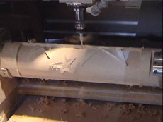
Figure 1.7 shows a machining scene example of a paint roller without any undesirable edge chipping, in which the feedrate values with “F” code are outputted online from the fuzzy feedrate generator [NAG 09]. The kind of wooden material used is a glued laminated wood. The maximum cutting depth of material removed is 3 mm. The wooden material was machined with the design as shown in Figure 1.6 giving the maximum cutting depth of 3 mm. An undesirable edge chipping occurred when feedrate values higher than about 800 mm/min were given. To suppress the edge chipping around the edges, the feedrates less than 800 mm/min were given by the fuzzy feedrate generator.
Figure 1.7. Machining scene of a wooden paint roller
1.4. Articulated-type industrial robot
1.4.1. Introduction
Industrial robots have drastically rationalized many kinds of manufacturing processes in industrial fields. The user interface provided by the robot maker has been almost limited to a teaching pendant. The teaching pendant is a useful and safe tool to obtain the position and orientation at the tip of a robot arm along a desired trajectory, but the teaching process is a very complicated and time-consuming task. In particular, when the desired trajectory includes a curved line, many through points have to be recorded in advance; the task is not easy.
For this decade, open architectural industrial robots as shown in Figure 1.8 have been produced from several industrial robot makers such as KAWASAKI Heavy Industries, Ltd, MITSUBISHI Heavy Industries, Ltd, YASKAWA Electric Corp., and so on. Open architecture, described in this section, means that the servo system and kinematics of the robot are technically opened so that various applications required in industrial fields can be planned and developed on the user’s side. For example, non-taught operations by collaborating with a CAD/CAM system can be considered due to the opened accurate kinematics. Also, force control strategy using a force sensor can be implemented due to the opened servo system. In this section, a 3D robot sander and a mold-polishing robot are introduced for wooden workpieces and metallic molds, respectively.
Figure 1.8. Open architecture industrial robot Mitsubishi PA10

1.4.2. For sanding a wooden workpiece
1.4.2.1. Surface-following control
The proposed robotic sanding system has two main features. One is that neither conventional complicated teaching tasks nor a post-processor (CL data → NC data) is required; the other is that the polishing force acting on the sanding tool and the tool’s position/orientation are simultaneously controlled along a free-formed curved surface. In this section, a surface-following control method indispensable for realizing the features is described in detail. A robotic sanding task needs a desired trajectory so that the sanding tool attached to the tip of the robot arm can follow the object’s surface, keeping contact with the surface from the normal direction. In executing a motion using an industrial robot, the trajectory is generally obtained in advance, for example, through a conventional robot teaching process. When the conventional teaching for an object with complex curved surface is conducted, the operator has to input a large number of teaching points along the surface. Such a teaching task is complicated and time-consuming.
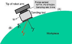
Next, a sanding strategy dealing with the polishing force is described in detail. The polishing force vector F(k) = [Fx(k) Fy(k) Fz(k)]T is assumed to be the resultant force of contact force vector f(k) = [fx(k) fy(k) fz(k)]T and kinetic friction force vector Fr(k) = –[Frx(k) Fry(k) Frz(k)]T that are given to the workpiece as shown in Figure 1.9, where the sanding tool is moving along the surface from (A) to (B). Fr(k) is written as follows:
where the first term is the Coulomb friction and the second is the viscous friction. µi and ηi (i = x, y, z) are the i-directional coefficients of Coulomb friction per unit contact force and of viscous friction, respectively. Each friction force is generated by f(k) and vt(k), respectively. The polishing force F(k) is represented by:
The polishing force magnitude can easily be measured using a three DOF force sensor attached between the tip of the arm and the sanding tool, which is obtained by:
where SFx (k), SFy (k), and SFz (k) are the directional components of force sensor measurements in the sensor coordinate system. The force sensor used is the NITTA IFS-67M25A with a sampling rate of 8 kHz. Although the IFS-67M25A is a six DOF force/moment sensor, the moment components are ignored because the moment data are not needed in the force control system. The error Ef(k) of polishing force magnitude is calculated by:
where Fd is the desired polishing force.
Figure 1.9. Polishing force F composed of contact force f and friction force Fr
1.4.2.2. Feedback control of polishing force
In the wooden furniture manufacturing industry, skilled workers usually use hand-held air-driven tools to finish the surface after machining or painting. These types of tools cause large magnitude vibrations with high frequency so that it is difficult for a skilled worker to sand the workpiece keeping a desired polishing force. Consequently, undesirable unevenness tends to appear on the sanded surface. To achieve good surface finishing, it is fundamental and effective to stably control the polishing force. When the robotic sanding system runs, the polishing force is controlled by the impedance model following force control with integral action given by:
where νnormal(k) is the velocity scalar; Kf is the force feedback gain; Kfi is the integral control gain; and Md and Bd are the desired mass and desired damping coefficients, respectively. ∆t is the sampling width. Using νnormal(k), the normal velocity vector νn(k) = [νnx(k) νny(k) νnz(k)] at the contact point is represented by:
where od(k) is the normal vector at the contact point, which is obtained from CL data.
1.4.2.3. Feedforward and feedback control of position
Currently, wooden furniture is designed and machined with 3D CAD/CAM systems and NC machine tools, respectively. Accordingly, the CL data generated from the main-processor of CAM can be used for the desired trajectory of the sanding tool. The block diagram of the surface-following controller implemented in the robot sander is shown in Figure 1.10. The position and orientation of the tool attached to the tip of the robot arm are feedforwardly controlled by the tangent velocity vt(k) and rotational velocity vr(k), respectively, referring to the desired position xd(k) and desired orientation od(k). vt(k) is given through an open-loop action so as not to interfere with the force feedback loop. The polishing force is regulated by vn(k) which is orthogonal to vt(k). vn(k) is given to the normal direction referring to the orientation vector od(k).
It should be noted, however, that using only vt(k) is not enough to precisely carry out desired trajectory control along CL data: actual trajectory tends to deviate from the desired one so that the constant pick feed (e.g. 20 mm) cannot be performed. This undesirable phenomenon leads to a lack of evenness on the surface. To overcome this problem, a simple position feedback loop with small gains is added as shown in Figure 1.10 so that the tool does not seriously deviate from the desired pick feed. The position feedback control law generates another velocity vp(k) given by:
where Sp = diag(Spx, Spy, Spz) is a switch matrix to realize a weak coupling control in each direction. If Sp = diag(1, 1, 1), then the coupling control is active in all directions; whereas if Sp = diag(0, 0, 0), then the position feedback loop does not contribute to the force feedback loop in all directions. Ep(k) = xd(k) — x(k) is the position error vector. x(k) is the current position of the sanding tool attached to the tip of the arm and is obtained from the forward kinematics of the robot. Kp = diag(Kpx, Kpy, Kpz) and Ki = diag(Kix, Kiy, Kiz) are the position and integral gain matrices, respectively. Each component of Kp and Ki has to be set to small values so as not to obviously disturb the force control loop. Finally, recomposed velocities ![]() ,
, ![]() , and
, and ![]() are summed up to make a velocity command v(k), and the v(k) is given to the reference of the Cartesian-based servo controller of the industrial robot. It is known that the complete six constraints, which consist of three DOF positions and three DOF forces in a constraint frame, cannot be simultaneously satisfied. However, the delicate cooperation between the position feedback loop and force feedback loop is an important key point to successfully achieve robotic sanding with curved surface.
are summed up to make a velocity command v(k), and the v(k) is given to the reference of the Cartesian-based servo controller of the industrial robot. It is known that the complete six constraints, which consist of three DOF positions and three DOF forces in a constraint frame, cannot be simultaneously satisfied. However, the delicate cooperation between the position feedback loop and force feedback loop is an important key point to successfully achieve robotic sanding with curved surface.
Figure 1.10. Block diagram of surface-following controller based on CL data

1.4.2.4. Experiment
In this section, experimental results of surface sanding are shown using the proposed robot sander. The overview of the robot sander developed based on KAWASAKI FS20 is shown in Figure 1.11. The orbital sanding tool is widely used by skilled workers to sand or finish a workpiece with curved surface. The base of the orbital sanding tool can perform eccentric motion. It is the reason why it is not only a powerful sanding tool but also gives good surface quality with less scratch. In this experiment, an orbital sanding tool is selected and attached to the tip of the robot arm via a force sensor. The diameter of the circular base and the eccentricity are 90 mm and 4 mm, respectively. The weight of the sanding tool is about 1.5 kg. When a sanding task is conducted, a circular pad with a sanding paper is attached to the base.
Figure 1.11. 3D robot sander with peripheral devices
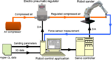
Figure 1.12 shows the sanding scene using the robot sander. In this case, the polishing force was satisfactorily controlled around a desired value. Hand-held air-driven tools are usually used by skilled workers to sand wooden material used for furniture. These types of tools cause large noise and vibration. Furthermore, the system of force control consists of an industrial robot, force sensor, attachment, hand-held air-driven tool, zig, and wooden material. Because each of them has a stiff property, it is not easy to strictly keep a desired polishing force without overshoot and oscillation. This is the reason why measured values of the polishing force tend to have spikes and noise. However, the result is much better than that by a skilled worker. Although it is difficult for a skilled worker to simultaneously keep the desired polishing force, tool position, and orientation even for a few minutes, the robot sander can perform the task more uniformly and perseveringly.
Figure 1.13a shows the target workpiece after NC machining, that is, before sanding, which is a representative shape that the conventional sanding machines cannot sand sufficiently. The pick feed in the NC machining is set to 3 mm. The surface before sanding has undesirable cusp marks higher than 3 mm for every pick feed. The robot sander first removes the cusp marks using a rough sanding paper #80, then sands the surface using a sanding paper of a middle roughness #220, and finally a smooth paper #400. The diameters of the pad and paper are cut to 65 mm, which are larger than that of the ball-end mill (17 mm) used in the NC machining process. The pad was put between the base and the sanding paper. The CL data were regenerated with a pick feed of 15 mm for the robotic sanding. The contour was made so as to be a small size with an offset of 15 mm to prevent the edge of the workpiece from over sanding. Table 1.1 shows the other sanding conditions and the parameters of the surface-following controller. These semi-optimum values were found through trial and error. Figure 1.13b shows the surface after the sanding process. The touch feelings with both the fingers and the palm were very satisfactory. Undesirable cusp marks were not observed at all. There was also no over sanding around the edge of the workpiece and no swell on the surface. Furthermore, we conducted a quantitative evaluation using a stylus instrument so that the measurements obtained by the arithmetical mean roughness (Ra) and max height (Ry) were around 1 µm and 3 µm, respectively. Figure 1.14 shows a piece of artistic furniture using the workpiece sanded by the robot sander. It was confirmed from the experimental result that the proposed robotic sanding system could successfully sand the wooden workpiece with curved surface.
Figure 1.12. Sanding scene of a curved workpiece
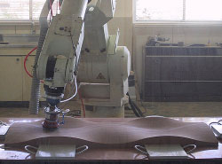
Figure 1.13. Curved surfaces before and after sanding process
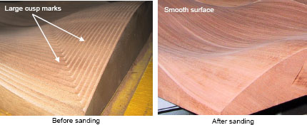
Table 1.1. Sanding conditions and control parameters
| Conditions or parameters | Values |
| Robot | KAWASAKI FS3OL |
| Force sensor | NITTA IFS-100M40A |
| Workpiece | Japanese oak |
| Size (mm) | 1,200 x 425 x 85 |
| Diameter of sand paper (mm) | 65 |
| Grain size of sand paper (#) | 80→220→400 |
| Desired polishing force Fd (kgf) | 1.0 |
| Feed rate ||vt|| (mm/s) | 30 |
| Pick feed of CL data (mm) | 15 |
| Air pressure of orbital sanding tool (kgf/cm2) | 4.0 |
| Desired mass coefficient Md (kgf.s2/mm) | 0.01 |
| Desired damping coefficient Bd (kgf.s/mm) | 20 |
| Force feedback gain Kf | 1 |
| Integral control gain for polishing force Kfi | 0.001 |
| Switch matrix for weak coupling control .Sp | diag(0, 1, 0) |
| Position feedback gain matrix Kp | diag(0, 0.01, 0) |
| Integral control gain matrix Ki, for position | diag(0, 0.0001, 0) |
| Sampling width ∆t (ms) | 0.01 |
Figure 1.14. Artistic furniture using the workpiece sanded by the robot sander

1.4.3. For mold finishing
1.4.3.1. Introduction
In the next stage, we try to include an industrial robot into the polishing process of polyethylene terephthalate (PET) bottle molds. As can be guessed, the sizes of the target workpieces are smaller than parts constructing furniture, that is, the radius of curvature is also smaller. In the manufacturing industry of PET bottle molds, 3D CAD/CAM systems and machining centers are similarly used, and these advanced systems have been drastically rationalizing the design and manufacturing process of metallic molds. On the contrary, most of the polishing processes after a machining process have been supported by skilled workers with capabilities concerning both dexterous force control and skillful trajectory control for an abrasive tool. The skilled workers usually use mounted abrasive tools of several sizes and shapes. In using these types of tools, keeping contact with the metallic workpiece with a desired contact force and a tangential velocity is the most important factor to obtain a high-quality surface. When performing a polishing task, it is also a key point that skilled workers reciprocatingly move the abrasive tool back and forth along the object surface.
Since the repetitive position accuracy at the tip of articulated-type industrial robots is 0.1 mm or thereabouts [NAG 08], it is very difficult to polish the surface of the metallic mold using only position control strategy. In the polishing process of PET bottle molds, the surface accuracy Ra of 0.1 µm or less is finally required for mirror-like finishing. In particular, when an industrial robot makes contact with a metallic workpiece, several factors that decrease the total stiffness of the system are included. They are called backlash, strain, and deflection, all of which exist not only in the robot itself but also in the force sensor, abrasive tool, jig, base frame, and so on. Therefore, it is meaningless to discuss the position accuracy at the tip of the abrasive tool attached to the robot arm. If position control is used for a polishing task where an abrasive tool and metallic workpiece contact each other, then both the stiffness of the robot and the total stiffness including the abrasive tool have to be extremely high. However, this problem and the problem on uncertainty of workpiece positioning have not been overcome.
It is actually known that no advanced polishing robots have been successfully developed yet on a commercial basis for such metallic molds with curved surface as in the case of PET bottle molds, due to the poor polishing quality and the complicated operation. The reasons why conventional polishing robots based on an industrial robot could not satisfactorily finish the curved surface of molds are listed as follows:
– Conventional industrial robots provide only a teaching pendant as a user-interface device. Precise teaching along a curved surface is extremely difficult and complicated.
– Kinematics and servo control, which are indispensable in developing a real-time application for mold polishing, have not been technically available as an open source to engineers and researchers.
– No successful control strategy has been proposed yet for mold polishing with curved surface. Compatibility between force control and position control is needed for higher surface quality.
Figure 1.15. Mold-polishing robot developed based on MOTOMAN UP6
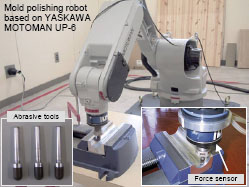
In this section, dexterous techniques are presented for understanding a skillful mold-polishing robot as shown in Figure 1.15. The CL data with normal vectors called multi-axis CL data can be used for not only a desired trajectory of tool translational motion but also a contact direction given to a mold. The impedance model following force control method keeps the polishing force, composed of a contact force and kinetic friction force, constant. A CAD/CAM-based position/force controller in Cartesian space by referring to such multi-axis CL data is proposed for the polishing robot with a ball-end abrasive tool. The surface polishing is achieved by controlling both the tool position along the CL data and the polishing force. The difference with the block diagram shown in Figure 1.10 is that the orientation of the tool is always fixed to z-axis in work coordinate system; the orientation component in CL data is used for the force direction to be given to a mold. The CAD/CAM-based position/force controller is applied to an industrial robot with an open architecture controller. The effectiveness and validity of the mold-polishing robot with the CAD/CAM-based position/force controller are demonstrated through an actual polishing experiment.
1.4.3.2. Basic polishing scheme for a ball-end abrasive tool
In this section, a control strategy that efficiently uses the contour of a ball-end abrasive tool is introduced for the mold polishing with curved surface. In polishing, the polishing force acting between the abrasive tool and the target mold is controlled. The polishing force is the most important physical factor that largely affects the quality of polishing, and assumed to be the resultant force of contact and kinetic friction forces. The mold-polishing robot is shown in Figure 1.15, in which a ball-end abrasive tool with a radius of 5 mm is attached to the tip of a six DOF-articulated industrial robot through a force sensor. The abrasive tool is generally attached to a portable electric sander so that the power of polishing is obtained by its high rotational motion, for example, 10,000 rpm. In this case, however, it is very difficult for a skilled worker to keep regulating suitably the power, contact force, and tangential velocity for many minutes according to an object’s shape, and so, undesirable over-polishing tends to occur frequently. Thus, to protect the mold surface against the over-polishing, the proposed polishing robot keeps the tool’s rotation slow, and polishes the mold using the resultant force Fr of the Coulomb friction and the viscous friction. Each friction force is generated by the contact force f in normal direction and the tangent velocity vt, respectively.
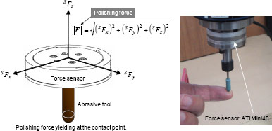
Figure 1.16 shows the control strategy considering the kinetic friction forces. In this figure, f is given by the normal velocity vn at the contact point between the abrasive tool and the mold. vn is yielded by the force controller given by equation [1.11]. In this chapter, the polishing force is defined as the resultant force of Fr and f, which can be measured by a force sensor. Figure 1.17 shows an example of a force sensor, ATI Mini40 six-axis force/torque sensor. It is assumed that the polishing is well performed by a hybrid control of the tool position and the polishing force. To avoid the interference between the abrasive tool and the mold, the orientation of the tool is not going to change and is always fixed to the z-axis in the work coordinate system. Fortunately, since PET bottle molds have no over-hang, a suitable contact point between the ball-end abrasive tool and the mold can always be obtained. The proposed polishing robot does not need to use any complex tools, vision sensors, teaching systems, and jigs so that it can be used in a simple manner.
Figure 1.16. Polishing strategy taking account of kinetic friction forces
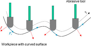
Figure 1.17. Polishing force measured by a force sensor
1.4.3.3. Feedforward and feedback control of tool position
Currently, metallic molds for PET bottle manufacturing are designed and machined with 3D CAD/CAM systems and machining centers, respectively. Accordingly, multi-axis CL data generated from the main-processor of CAM can be used for the desired trajectory of an abrasive tool. The block diagram of the CAD/CAM-based position/force controller implemented in the mold-polishing robot is almost the same as Figure 1.10, except that the tool axis is always fixed to the z-axis in the work coordinate system. In other words, the tool orientation is not changing to maintain the force control stability and to uniformly abrade the contour of the ball-end abrasive tool.
The position of the abrasive tool is feedforwardly controlled by the tangential velocity vt(k) given by:
where vtangent is the velocity scalar which means the feedrate. vt(k) is given through an open-loop action so as not to interfere with the normal velocity vn(k). On the other hand, the polishing force is controlled by vn(k) which is orthogonal to vt(k). vn(k) is given to the normal direction referring to od(k). It should be noted, however, that using only vt(k) is not enough to execute desired trajectory control along the CL data, that is, the tool is not able to conduct regular pick-feed motion, for example, with a given pick feed of 0.1 mm. To avoid this undesirable phenomenon, a simple position feedback loop with a small gain is added as shown in Figure 1.10 so that the abrasive tool does not deviate from the desired pick-feed motion. The position feedback control law generates another velocity vp(k) given by equation [1.12]. Finally, the velocities vn(k), vt(k), and vp(k) are summed up, and are given to the reference of the Cartesian-based servo controller of the industrial robot. The CAD/CAM-based position/force controller neither deals with the moment nor with the rotation, and also the origin of the constraint space (force space) is always chosen at the contact point. Accordingly, although a paper by Duffy states the fallacy of modern hybrid control theory such as dimensional inconsistency, dependence on the choice of origin of the coordinates [DUF 90], our proposed system is not affected.
1.4.3.4. Experiment
To evaluate the validity and effectiveness of the mold-polishing robot using the CAD/CAM-based position/force controller, a fundamental polishing experiment is conducted using an aluminum mold machined by a machining center. The objective of the fundamental polishing is to remove all cusp marks on the curved surface whose heights are around 0.3 mm. The fundamental polishing before finishing process is one of the most important processes to create the best appearance for mirror-like surfaces. If the undesirable cusp marks are not uniformly removed in advance, then it is very difficult to finish the mold with a mirror-like surface without scratches, swells, and over-polishing; however, much time would be spent for the finishing process.
Figure 1.18 shows the mold-polishing robot developed based on an industrial robot KAWASAKI FS03 with open control architecture. The industrial robot provides several useful Windows API functions such as a Cartesian-based servo control and forward/inverse kinematics. A ball-end abrasive tool is attached to the tip of the robot arm via a force sensor. The surface was polished through three steps, making the grain size of the abrasive tool gradually smaller, that is, from #220, #320 to #400. Figure 1.19 shows the polishing scene using the proposed robot. When the polishing robot runs, the abrasive tool reciprocatingly rotates with ±40 deg/sec using the sixth axis of the robot so that the tool contour can be abraded uniformly. If the abrasive tool is uniformly abraded keeping the ball-end shape, the robot can keep up the initial polishing performance. Although the tool length gradually becomes shorter due to tool abrasion, the force controller absorbs the uncertainty concerning the tool length. The y-directional position feedback loop delicately contributes to the force feedback loop to keep the constant pick feed even around the inclination part of the mold.
Figure 1.18. Mold-polishing robot developed based on KAWASAKI FS03

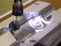
Figure 1.19. Polishing scene of PET bottle mold
1.5. Desktop Cartesian-type robot
1.5.1. Background
The finishing of an LED lens mold after a machining process requires high accuracy, delicateness, and skill such that it has not been successfully automated yet. Generally, a target LED lens mold has many concave areas precisely machined with a tolerance of ±0.01 mm as shown in Figure 1.20, where each diameter is 3.6 mm. This means that the target mold is not axis-symmetric so that conventional effective polishing systems, which can deal with only axis-symmetric workpieces, cannot be applied. Accordingly, such an axis-asymmetric lens mold is polished by a skilled worker in most cases. Skilled workers generally finish small lens molds using a wood-stick tool with diamond paste while checking the finished area through a microscope. However, the smaller the workpiece is, the more difficult the task is. In particular, it is required for an LED lens mold to handle the surface uniformly and softly so that high resolutions for both position and force are indispensable for the corresponding mechatronics system.
Figure 1.20. LED lens mold

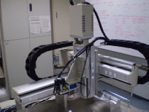
In this section, a new desktop Cartesian-type robot with compliance controllability is presented for finishing metallic molds with a small curved surface [NAG 10]. The Cartesian-type robot consists of three single-axis devices. A wood-stick tool attached to the tip of the z-axis has a ball-end shape. Also, the control system of the robot is composed of a force feedback loop, position feedback loop, and position feedforward loop. The force feedback loop controls the polishing force consisting of tool contact force and kinetic friction force. The position feedback loop controls the position in a spiral direction. Furthermore, the position feedforward loop leads the tool tip along a spiral path. The Cartesian-type robot delicately smoothes the surface roughness at about 50 µm height on each concave area, and finishes the surface with a high quality.
1.5.2. Cartesian-type robot
To finish small concave areas as shown in Figure 1.20, a novel robot is proposed in this section. Figure 1.21 shows the proposed desktop Cartesian-type robot consisting of three single-axis devices with a position resolution of 1 µm. The three single-axis devices are used for x-, y-, and z-directional motions. A servo spindle motor is also used for the rotational motion of the tool axis. The servo spindle motor with a reduction gear and the tool axis work together with a belt. The size of the robot is 850 mm width, 645 mm depth, and 700 mm height. The single-axis device is a position control device ISPA with high-precision resolution provided by IAI Corp., which is composed of a base, linear guide, ball-screw, AC servo motor, and so on. The effective strokes in x-, y-, and z-directions are 400, 300, and 100 mm, respectively. The effective stiffness in the z-direction is about 177.7 N/mm when a wood-stick tool is used. Therefore, it is expected that the force resolution about 0.178 N can be performed due to the position resolution of 1 µm.
Figure 1.21. Cartesian-type robot with compliant motion capability
1.5.3. Design of weak coupling control between force feedback loop and position feedback loop
A skillful control strategy is proposed for an LED lens mold with aspherical surface. An abrasive tool moves along a spiral path as shown in Figure 1.22 while stably keeping the polishing force at a desired value. The weak coupling controller has been already proposed for the PET bottle polishing robot, in which the force feedback loop and position feedback loop are slightly coupled in a selected direction such as a pick-feed direction. In this case, a zigzag path is generally used for the desired trajectory so that a position feedback control is active only in the pick-feed direction, for example, the y-direction. On the contrary, in the case that an LED lens mold is finished by the Cartesian-type robot, the direction of the force feedback loop, that is, normal direction, changes gradually all the time when the abrasive tool contacts with the bottom center of a concave area and rises along a spiral path. Since the contact force is given to the normal direction at the contact point, the following three conditions are considered:
1. Around the bottom center of an LED lens mold, the x- and y-directional components of the normal vector are almost 0. Therefore, the force feedback control system should be constructed in the z-direction, and the position feedback control system also should be given to the x- and y-directions.
2. The z-directional component of the normal vector is almost 0 around the upper area so that the direction of the force control system periodically changes in the x- and y-directions according to the spiral path. Hence, the position feedback control system is assigned only in the z-direction.
3. Around the middle area, the x-, y-, and z-directional components of the normal vector change instantaneously along the spiral path so that the force feedback control system should be designed in the x-, y-, and z-directions. The weak coupling control is not needed in the cases of 1 and 2. In the case of 3, however, the weak coupling control is applied to realize a regular pick-feed motion in the z-direction, while performing the stable polishing force. It is further important to independently regulate the weight of the coupling control coping with the shape of the workpiece. To deal with the problem, each component of the position feedback gain Kp = diag(Kpx, Kpy, Kpz) is varied as:
where α is the basic gain for the weak coupling control. nz (0 ≤ nz ≤ 1) is the z-directional component of the normal direction vector. When an abrasive tool rises along the spiral path as shown in Figure 1.22, nz varies from 1 to 0. For example, if α is given 0.001, Kpx and Kpy varies from 0.001 to 0, and Kpz varies from 0 to 0.001 with the rise of a thin wood-stick tool.
Figure 1.22. Spiral path used for desired trajectory of LED lens mold

1.5.4. Frequency characteristic of force control system
Next, the frequency characteristics of the force control system are evaluated through a simple force control experiment. A thin wood-stick tool (ϕ = 1 mm) is used. Figure 1.23 shows an example of the desired force whose frequency is set to 1 Hz. The peak-to-peak value of desired force is 4 N. The frequency characteristics are measured within the range from 0 to 15 Hz in this order. The frequency of 0 Hz means that the desired force is set to the constant value 5 N. Figure 1.24 shows the frequency characteristics of the amplitude in the case that the wood-stick tool is used. Although 0 dB is the ideal result in the force control system, that is, the response can almost completely follow the reference shown in Figure 1.23, values over 0 dB tend to occur with the increase of the frequency. This phenomenon is caused by undesirable overshoots and oscillations in the stiff force control system. However, the desired polishing force in actual finishing tasks is generally set to a constant value, for example, 20 N so that the frequency characteristic is almost no problem.
Figure 1.23. An example of desired force

Figure 1.24. Frequency characteristics of force control system

1.5.5. Finishing experiment of an LED lens mold
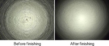
In this section, the proposed system is applied to the finishing of a test workpiece of an LED lens mold. A thin ball-end tool lathed from a wooden stick is used, whose tip diameter is 1 mm. Figure 1.25 shows the finishing scene of the workpiece, where a special oil including the diamond lapping paste is being poured. Figure 1.26 shows the large-scale photos of the surfaces before and after the finishing process. It is observed that small cusps on the concave surface can be removed uniformly. The effectiveness and promise are confirmed from the finishing experiment.
Figure 1.25. Finishing scene of a test workpiece
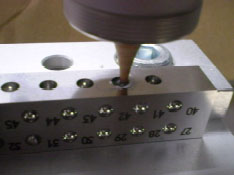
Figure 1.26. Large-scale photos of surfaces before and after finishing process
1.6. Conclusions
Currently, 3D CAD/CAM systems are widely used in various manufacturing fields and applications. The main-processor of CAM generates cutter location data called CL data, which consists of precise position and its normal direction components. Machine tools and robots can display more superior abilities and functions by minutely using the CL data. This chapter has experimentally described and evaluated several mechatronics systems based on a 3D CAD/CAM system. A five-axis NC machine tool with a tilting head, a three-axis NC machine tool with a rotary unit, articulated-type industrial robots for furniture sanding and mold polishing, and a desktop Cartesian-type robot for LED lens mold finishing have been introduced.
Finally, we hope that the chapter will be useful not only for engineers in related industrial fields, but also for students pursuing education and research concerning NC machine tools, 3D machining, advanced control system, CAD/CAM, industrial robot, automation, and so on.
1.7. Bibliography
[DUF 90] DUFFY J., “The fallacy of modern hybrid control theory that is based on orthogonal complements of twist and wrench spaces”, Journal of Robotic Systems, vol. 7, no. 2, 1990, pp. 139–144.
[FUJ 03] FUJINO K., SAWADA Y., FUJII Y., OKUMURA S., “Machining of curved surface of wood by ball end mill—effect of rake angle and feed speed on machined surface”, Proceedings of the 16th International Wood Machining Seminar, part 2, 2003, pp. 532–538.
[NAG 08] NAGATA F., HASE T., HAGA Z., OMOTO M., WATANABE K., “Intelligent desktop NC machine tool with compliance control capability”, Proceedings of the 13th International Symposium on Artificial Life and Robotics, 2008, pp. 779–782.
[NAG 09] NAGATA F., KUSUMOTO Y., WATANABE K., “Intelligent machining system for the artistic design of wooden paint rollers”, Robotics and Computer-Integrated Manufacturing, vol. 25, no. 3, 2009, pp. 680–688.
[NAG 10] NAGATA F., MIZOBUCHI T., TANI S., HASE T., HAGA Z., WATANABE K., HABIB M.K., KIGUCHI K., “Desktop orthogonal-type robot with abilities of compliant motion and stick-slip motion for lapping of LED lens molds”, Proceedings of 2010 IEEE International Conference on Robotics and Automation (ICRA 2010), 2010, pp. 2095–2100.
[NAG 96] NAGATA F., WATANABE K., “Development of a post-processor module of 5-axis control NC machine tool with tilting-head for woody furniture”, Journal of the Japan Society for Precision Engineering, vol. 62, no. 8, 1996, pp. 1203–1207 (in Japanese).
1 Chapter written by Fusaomi NAGATA, Yukihiro KUSUMOTO, Keigo WATANABE and Maki K. HABIB.