
Microsoft SQL Clustering Core Capabilities
SQL Server allows fail-over and fail-back to or from another node in a cluster. In an “active/passive” configuration, an instance of SQL Server will be actively servicing database requests from one of the nodes in a SQL cluster (active node). Another node will be idle until, for whatever reason, a fail-over occurs (passive node). With a fail-over situation, the secondary node (the passive node) will take over all SQL resources (databases and MS DTC) without the end-user ever knowing that a fail-over has occurred. The end-user might experience some type of brief transactional interruption because SQL clustering cannot take over “in flight” transactions. However, from the end-user's point-of-view, they are still just talking to a single (virtual) SQL Server and truly won't know which node is fulfilling their requests. This type of application transparency is a highly desirable feature that is making SQL clustering more and more popular as a high availability option.
In an ”active/active” configuration, SQL Server runs multiple servers simultaneously with different databases, allowing for organizations with more constrained hardware requirements (that is, no designated secondary systems) to enable fail-over to or from any node without having to set aside (idle) hardware.
By taking advantage of the clustering capabilities of Windows 2000 Advanced Server, SQL Server 2000 provides the high availability and reliability required of an enterprise class database management system. You can install up to 16 instances of Microsoft SQL Server 2000 in a Microsoft cluster service.
SQL Clustering Is Built on MSCS
As you already have seen in Chapter 4, “Microsoft Cluster Services,” MSCS is capable of detecting hardware or software failures and automatically shifting control of the server to a healthy node. SQL Server 2000 implements fail-over clustering based on the clustering features of the Microsoft Clustering Service. In other words, SQL Server is a fully “cluster aware” application. Windows 2000 Advanced Server would normally handle up to two servers, whereas Windows 2000 Datacenter can handle up to four servers in a single cluster. The fail-over cluster shares a common set of cluster resources (or cluster groups) such as clustered (shared) disk drives. You can install SQL Server on as many nodes as you want; this is only limited by the operating system limitations. Each node must be running the same version of MSCS as well.
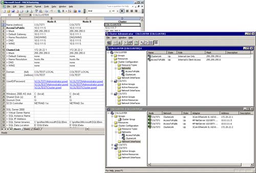
Figure 5.1 shows a typical two-node clustering configuration that has been configured in an active/passive mode. COLTST1 and all of the highlighted cluster group resources of COLTST1 is the “active” node. COLTST3 is the “passive” node. In the event that COLTST1 should fail, COLTST3 (via MSCS) will pick up control of these cluster group resources. So, the first step in creating a SQL Server clustering configuration entails installing the MSCS feature.
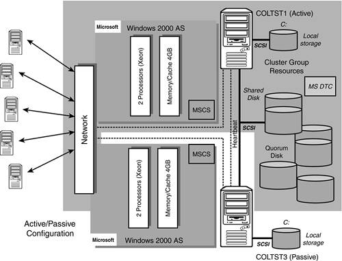
The short list of resources controlled by the cluster will be
Physical Disks (Q:—Quorum disk, E:—Shared disks, F:, so on)
Cluster IP Address
Cluster Name (Network Name)
MS DTC
SQL Server Virtual IP Address
SQL Server Virtual Name (Network Name)
SQL Server
SQL Agent
In Chapter 4, we created the first three cluster group resources (Physical Disks, Cluster IP Address, and Cluster Name). We must now add MS DTC (Microsoft Distributed Transaction Coordinator) and the SQL Server resources to the cluster to complete the installation of SQL clustering.
Configuring MS DTC for Use with SQL Clustering
MS DTC is required in a cluster for distributed queries and two-phase commit transactions. SQL Server relies on MS DTC heavily in this regard. After you have installed MS Cluster Services (as outlined in Chapter 4) please verify that MS DTC has been installed as well.
On each node of the cluster, check your “services” to see if Distributed Transaction Coordinator is there. If not, you will have to do this now by running DTCSetup.exe on each node in the cluster. DTCSetup.exe can be found in the Windows/System32 folder of each node. Follow these simple steps:
1. | Verify that node A has control of the clusters resource groups (via the cluster administrator). |
2. | Then, first from node A, run the following from a DOS prompt: C:WindowsSystem32> DTCSetup.exe This will copy the needed files to the system32 folder. |
3. | Check the event viewer to make sure that the install was successful on this node. If this fails, you will have to start over, or even have to undo entries in the registry. |
4. | You might also be prompted to run DTCSetup.exe on the second node. [Do so, only if prompted.] |
Once the installation of MS DTC is completed, you can now configure it to be a resource within cluster services. This is done by running the comclust.exe program on each node which will configure MS DTC to run in clustered mode. Make sure you do this on both nodes, one at a time.
1. | Again, from a DOS command prompt, run comclust.exe on node A. This will configure MS DTC for use with cluster services. C:WindowsSystem32> comclust.exe |
2. | After this step completes on the first node, repeat this step on node B. |
3. | Verify that the DTCLOG folder has been created on the cluster shared disk. NOTE: By default, the MSDTC service will start with a local system account. This local system account must be given full permissions to the DTCLOG folder. |
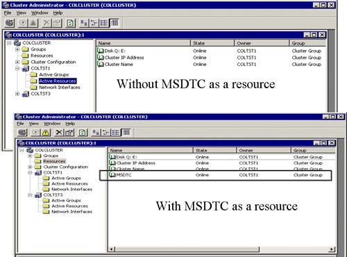
In the top portion of Figure 5.2, the Cluster Administrator window shows that MS DTC is not listed as a resource yet. Once you configure MS DTC as a resource (via comclust.exe), it will appear as a resource in the cluster group (as you can see in the bottom Cluster Administrator window of Figure 5.2).
Laying Out a SQL Cluster Configuration
When you install SQL Server in a clustered server configuration, you create it as a ”virtual” SQL Server. In other words, a virtual SQL Server will not be tied to a specific physical server. Figure 5.3 shows the same two-node cluster configuration with all of the SQL Server components identified. This virtual SQL Server will be the only thing the end-user will ever see. As you can also see in Figure 5.3, the virtual server name is VSQLDBARCH and the SQL Server Instance name is VSQLSRV1. From the network's point of view the fully qualified SQL Server instance will be “VSQLDBARCHVSQLSRV1.” Figure 5.3 also shows the other cluster group resources that will be part of your SQL clustering configuration. These, of course, are MS DTC (as we configured earlier), SQL Agent, and the shared disk where your databases will live. A SQL Agent will be installed as part of the SQL Server installation process and is associated with the SQL Server instance it is installed for. Same is true for MS DTC; it will be associated with the particular SQL Server instance that it is installed to work with (VSQLSRV1 in this case).
Now, before we go too much further, it would be a good time to talk about how you should lay out a SQL Server implementation on the shared disks that are managed by the cluster. The overall usage intent of a particular SQL Server instance dictates how you might choose to have configured your shared disk and how it might be best configured for scalability and availability.
Figure 5.4 shows the typical RAID levels used in a high availability disk configuration, the fault tolerance to expect, the number of logical I/Os per read, the physical I/Os per read, number of logical I/Os for a write operation, and the number of physical I/Os per writes. In general, RAID 0 is great for storage that doesn't need fault tolerance; RAID 1 or 10 is great for storage that needs fault tolerance, but doesn't have to sacrifice too much performance (like with most Online Transaction Processing Systems—OLTP); and RAID 5 is great for storage that needs fault tolerance, but whose data doesn't change that much (low data volatility as in many DSS/Read Only systems).
Figure 5.4. Different I/O costs of the typical RAID level configurations used in HA.
What this all translates to is that there is a time and place to use the different fault tolerant disk configurations. Figure 5.5 provides a very good “rule of thumb” to follow for deciding which SQL Server database file types should be placed on which RAID level disk configuration. This would be true regardless of whether the RAID disk array was a part of a SQL cluster or not.
The Quorum Drive
As part of this high availability disk configuration, the quorum drive should be isolated to a drive all by itself and be mirrored to guarantee that it is available to the cluster at all times. Without it, the cluster won't come up at all and you won't be able to access your SQL databases.
SQL Server Database Files
One or more physically separate shared disk arrays can house your SQL Server managed database files. In a SQL Server database, it is highly desirable to isolate your data files away from your transaction log files for any database that has volatility (like with OLTP systems). In addition, perhaps one of the most critical databases in a SQL Server instance is the internal shared database of TempDB. TempDB should be isolated away from your other databases and perhaps placed on some high performing disk configuration such as RAID 10. SQL Server requires that TempDB be allocated at server startup time, so the location of TempDB should be protected rigorously. Do not place TempDB on a RAID 5 disk array! The write overhead is far too much for this internally used (and shared) database. In general, put your OLTP SQL Server database data/transaction log files on RAID 10 (including Master DB, Model DB, and MSDB) and your DSS/Read Only data/transaction log files on RAID 5.
Figure 5.6 shows an example of a typical production SQL Server instance that has three application databases on it and how all of these database files might be laid out over a shared multi-disk configuration. Master DB and the DSS (read only) database were crated on the E: Drive (a RAID 5 disk array); TempDB database was isolated to the F: Drive (a RAID 10 disk array). The other two OLTP databases were spread out over the G: and H: drives (also RAID 10 disk array), and the Q: drive was reserved for the quorum files for MSCS (a RAID 1 or RAID 10 disk array).
Figure 5.6. Sample SQL Server/SQL clustering database file allocations across multiple shared disks.
Network Interfaces
As you can see in Figure 5.7, one final glance with Cluster Administrator shows that both COLTST1 and COLTST3 nodes and their private and public network interfaces are completely specified and their state (status) is “up.” If you like, you should double-check these IP addresses and network names with the Excel spreadsheet that was created for this cluster specification.
Figure 5.7. The state of the cluster network interfaces and their correspondence to our Excel spreadsheet specification.
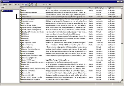
Cluster Service
As you can see in Figure 5.8, the Cluster Service is running and has been started by the cluster login account for the COLTEST domain as was required.
Figure 5.8. Make sure Cluster Service is running and started by the cluster account for the domain.
CAUTION If Cluster Service is not started, and won't start, you will not be able to install SQL clustering. You will have to remove and then re-install MSCS from scratch. A little extra advice is to browse the Event Viewer to familiarize yourself with the types of warnings and errors that start appearing with Cluster Service.
As you add more things to be managed by the cluster (such as SQL Server), you will want to be able to distinguish the new events from the old (normal) events. Looking at Figure 5.9, you can see the major events that describe the state of the cluster. These are all ClusSvc event sources. The event IDs to focus on are Event ID 1128, 1125, 1061, and 1122.
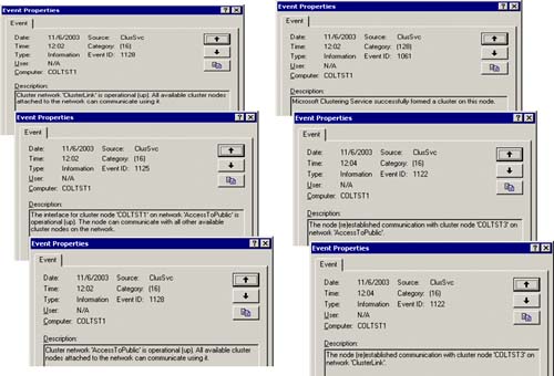
Event ID 1128 shows the cluster network state (the public network and the private network that has been defined in the cluster). For example: Cluster Network “ClusterLink” is operational.
Event ID 1125 shows the interface state (the machine and which network is being used). For example: COLTST1 on “AccessToPublic” network is operational.
Event ID 1122 shows the node communication state for the cluster node. For example: COLTST3 successfully established communication on the “AccessToPublic” network with the cluster.
Okay, the cluster is intact, all services are intact, and the needed resource groups are being managed by the cluster. You will now be able to build up the two-node SQL cluster.