
Chapter 8: Designing the Power Platform Solution
In this chapter, you will learn how to lead the design process using our fictional case study at Inveriance Corps and communicate decisions through effective design visualizations. You will create a blueprint that defines the Solution Architecture, PowerApps Portals user prototypes, application life cycle management (ALM) processes, and an automation strategy that leverages Power Automate capabilities. You will learn how to design supportable customizations, component reuse patterns, and data migration strategies. By the end of this chapter, you will be able to group requirements based on user roles or tasks, and design data visualization strategies.
In this chapter, we are going to cover the following topics:
- Defining the Power Platform Solution Architecture topology
- Power Platform detailed design
- Facilitating understanding through descriptive visual designs
- Defining user experience prototypes for customer-facing and internal applications
- Designing data migration strategies
- Defining the application life cycle management process
This chapter emphasizes descriptive and compelling design visualizations for Model-Driven Apps, PowerApps Portals, and Canvas Apps, all of which are a vital part of the implementation as they facilitate understanding of the task at hand for all team members and project stakeholders.
Defining the Power Platform Solution Architecture topology
A Solution Architecture topology describes the logical and physical components that make up a Power Platform implementation. During the design process, you will likely ask yourself the question, what is the best software architecture pattern? You would then look at the wide variety of tools and services and options available within the Microsoft ecosystem and find the answer to your initial question. The answer is that there is no best architectural pattern. When designing a Power Platform implementation, Solution Architects review the platform as-is, the desired short and long-term goals, and design the architecture that is best suited to fulfill these goals. The design decision process considers technical, commercial, and business constraints, guiding the implementation toward solutions that can be achieved within budget and desired timescales.
The product roadmap and future Power Platform feature upgrades and deprecations are also considered during the design stages. The Solution Architect creates a long-term roadmap for the Power Platform implementation itself.
In this section, you will work through the various considerations and decisions when designing a Power Platform solution, to come up with the best possible design for an organization’s specific situation.
Understand the current state
Power Platform solutions are often implemented to complement or replace existing business application architecture and business processes. During the discovery and analysis phases, which were discussed in previous chapters, you will understand the extant systems and processes and how a Power Platform solution is best positioned to add value to the organization. Armed with the information gathered, you would create an architecture topology diagram with just enough detail to facilitate design discussions and draft the proposed Solution Architecture.
As a Solution Architect, you will decide the level of detail to be included in the topology diagrams for the as-is architecture, depending on the complexity and the required level of integration of existing systems. The following diagram illustrates a typical as-is architecture topology diagram for an organization looking to transform its bespoke time tracking, customer portal website, and Excel/SQL-based CRM systems:
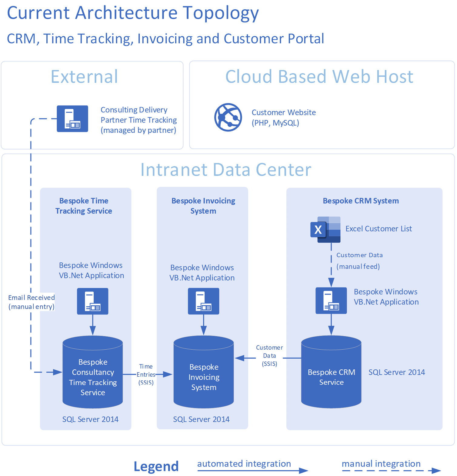
Figure 8.1 – Example as-is architecture topology diagram
The preceding diagram describes the existing CRM, time tracking, and customer portal systems within an organization, illustrating the type of integrations between systems at a high level.
Additional details (for example, network layers and protocols, security, and authentication processes) may be added to the diagram if it would help team members visualize the to-be Solution Architecture. Conversely, a simpler solution diagram (or no diagram at all) would also suffice, depending on the complexity of the implementation.
Considering existing systems, databases, and locations, the as-is architecture diagram helps guide the design decisions for the Power Platform solution.
Understand the to-be state
The discovery, requirements capture, and fit-gap analysis exercises discussed in the previous chapters describe activities that result in a deep understanding of the organization’s goals and expectations from a Power Platform solution. These are some of the typical documents and artifacts that will help create a Power Platform Solution Architecture topology:
- Discovery phase documentation, notes, and architectural overview diagrams
- Requirements capture documentation and workshop notes
- Business process models
- Data models
- Fit-gap analysis results
Having reviewed the preceding documentation and collaborated with the organization’s stakeholders, SMEs, and system owners, Solution Architects are ideally positioned to design a Power Platform architecture topology that addresses the organization’s short and long-term goals.
Considering the project’s constraints
Most projects will have explicit or implied constraints, be they financial, technical, or operational. When designing the Solution Architecture topology for an organization, these constraints play a part in the decision process. The project will have specific budgetary and financial constraints that the implementation must adhere to to be accepted by the organization. When defining the Solution Architecture, you would typically take into account the following costs:
- Power Platform licensing
- Dynamics 365 application user licenses
- Power Platform and Azure storage
- Third-party or external component licenses
- Implementation build
- Ongoing support and maintenance
- Other one-off or running costs that may apply
As a Solution Architect, you will prepare a cost calculator that allows the business to make an informed decision regarding any proposed solution’s ongoing costs and maintenance overheads. The following figure illustrates a solution cost calculator that’s presented to the customer when implementing a Power Platform and Dynamics 365 Sales implementation:

Figure 8.2 – Example Power Platform solutions options selector spreadsheet
The preceding example worksheet presented the customer with two options for back-office users and five for field resources, allowing the project owners and stakeholders to make an informed decision.
Presenting the customer with several architecture options and the associated licensing and build costs allows the business to select the best solution to fulfill their needs within the project’s financial constraints. It also provides transparency and a platform for collaboration with the customer.
While consulting with the organization, you can present the pros and cons of each Solution Architecture option, and help product owners select the best option for their needs. Once an option has been selected, a more detailed architectural blueprint can be created for the Power Platform solution.
Architecture that fits short and long-term objectives
When designing the Solution Architecture topology for a Power Platform project, the Solution Architects take into account the short-term project goals (replacing legacy systems may be a typical example) and the long-term goals (which may include all systems and business processes or a complete overhaul and digital transformation of the organization). The Solution Architecture topology will take two objectives into account, and propose a solution that fulfills both these goals. Let’s take a look at these.
Pillar for Great Solution Architecture – Balancing Decisions
The Solution Architected topology you propose will take future goals into account. For example, you may find that short-term goals could be fulfilled with a simple Power Platform model-driven app. However, the long-term goals may be more closely aligned with the Dynamics 365 Sales application.
During the design process, you will delve deeper into the long-term goals to decide whether a Power App, a Dynamics 365 application, or a combination of both, would be the best solution for the business in terms of build complexity, licensing, and maintenance costs. Note that a move from Power Apps to a Dynamics 365 application would typically require a substantial migration effort.
Linking the architectural building blocks
When designing the Solution Architecture topology for a Power Platform implementation, you will consider how components interact with each other and external systems. The discovery and analysis phases of the project will have yielded several useful documents, and the requirements capture phase will have identified systems to be integrated. The Solution Architecture topology will take those systems and integrations into account, and illustrate the connections between the Power Platform and external systems. The following diagram illustrates the interaction between Power Platform components and an external timesheet tracking system:

Figure 8.3 – Example Power Platform solutions architecture topology showing interactions
The level of detail in the Solution Architecture topology diagrams will vary, depending on the requirements and complexity of the project. Some projects will also have stringent security directives, which the architecture topology will need to address. As the Power Platform Solution Architect, you will decide on the level of complexity required to illustrate the Solution Architecture topology, including enough detail for the design to be useful as a discussion point with product owners and as a design guide for the implementation team.
Presenting multiple architecture options to facilitate selection
It is often useful to provide an organization with more than one implementation option, allowing product owners to review the pros and cons of each option. An options selector listing the various pros and cons is a useful tool for you as the Solution Architect and the customer as the reviewer.
The following diagrams present two options for implementing a Power Platform solution. The first option includes a Model-Driven app as the main component:
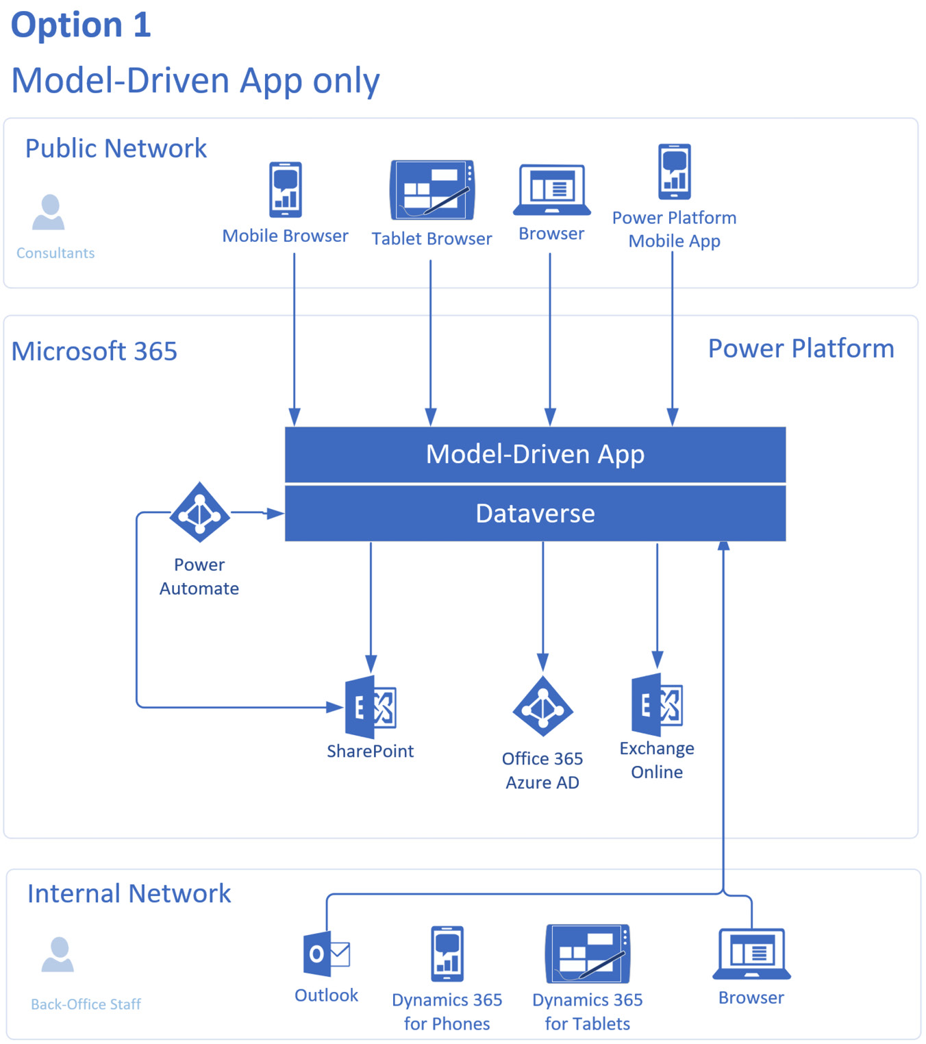
Figure 8.4 – Example solution topology diagram presenting a Model-Driven app-only option
The second diagram presents a solution that includes a Model-Driven App and Power Pages:

Figure 8.5 – Example solution topology diagram presenting a second option, including a Model-Driven app and Power Pages
Having presented various options and the pros and cons of each, you will be in a position to decide, together with the product owners, on the best option to fulfill the organization’s short and long-term goals. The selected option can then be expanded on, and the Solution Architecture topology diagram can be enhanced to include enough detail for the implementation team to use as a blueprint.
Review iterations
While creating the Solution Architecture topology, you will go through several review iterations with the product owners, stakeholders, and other individuals with a vested interest in the Power Platform implementation. These review sessions aim to further refine the Solution Architecture, with each session bringing the design closer to the organization’s needs.
Product roadmap
While creating the Solution Architecture topology, you will take into account the product roadmap for Power Platform components, the business applications, and any third-party components being considered. New features are constantly being added to Power Platform, and these are announced in advance for preview before they are available for general availability. As new functionality is introduced, certain features are, at times, deprecated. These deprecations or application end-of-life are also announced. Solution Architects review upcoming features and new applications so that the architecture being created is viable throughout the lifetime of the solution.
Reference Documentation
The following link provides details of upcoming Power Platform releases, Dynamics 365 updates, and product applications:
https://powerapps.microsoft.com/roadmap/
Power Platform detailed design
The Solution Architecture topology provides the structure for the Power Platform solution. Once this foundation is in place, you can create a detailed design for the implementation. This section discusses the various patterns, considerations, and ideas for creating detailed Power Platform designs.
Power Apps design patterns
Having decided that you will be using Power Apps for your project, you are presented with several choices. Typically, you will select from one of these three main options:
- Custom App: Power Apps can be built from the ground up, using the Dataverse as a base, and extending it to complete the project. Tables, columns, and forms are built to match a wide range of requirements. While Power Apps provide flexibility through a blank canvas approach, the trade-off may be in the implementation time. Building a sales-related Model-Driven application from scratch may take longer than using a base Dynamics 365 application or a partner starter app.
- Dynamics 365: Dynamics 365 is, in essence, a Power Apps application that has been built to fulfill specific business needs (for example, customer service, sales, marketing, and more). As a Solution Architect, you will, at times, find using Dynamics 365 applications to be the best solution for the organization in terms of implementation time and technical capabilities.
- Partner App: Microsoft partners have created a wide range of Power Platform and Dynamics 365 applications that can be leveraged, expediting the implementation of Power Platform solutions, and providing enhanced capabilities not available with the base Microsoft product. As a Solution Architect, you will know these partner applications or research them during the design process, to identify whether a partner application is the best solution to fulfill a requirement.
Having reviewed your options and selected the one that best suits the project, you can drill down into the implementation details and select the types of Power Apps to be used. The next section discusses the design process for the various Power Platform components.
Dataverse design
Most Power Apps rely on Dataverse for storing and processing configuration and operational data. Canvas Apps often use Dataverse, though not exclusively as they may work off alternative data sources such as SharePoint, Excel, and many more.
When building a Power Apps application, Solution Architects define the tables that hold operational data. An entity-relationship diagram allows all members of the implementation team to work off the same page, and the resulting data structure is more likely to be coherent and maintainable.
When using Dynamics 365, several Dataverse tables are included to support the functionality of the application. When opting for a custom Dataverse model-driven app, the majority of the tables will be created during the implementation phase, as the number of tables included as standard is limited to basic entities such as contacts, accounts, and tasks.
Note on Restricted Tables
Specific tables are restricted, depending on the available product licenses. For example, the Case table requires one of these licenses:
Dynamics 365 for Customer Service Professional edition
Dynamics 365 for Customer Service Enterprise edition
Dynamics 365 Customer Engagement plan
Dynamics 365 plan
For further details, please reference https://docs.microsoft.com/power-apps/maker/data-platform/data-platform-restricted-entities.
Model-Driven Apps design
Designing Model-Driven Apps tends to be a visual exercise. Alongside entity-relationship diagrams, you will be responsible for designing application forms, views, business process flows, and the business process that underpins the application.
Functional consultants and Power Platform developers will rely on your designs to build the solution. Therefore, the designs will become a guiding map through which the implementation team will draw its inspiration and guidance. With a design in place, the project has a higher chance of resulting in a coherent Model-Driven App that is easy to build, use, and maintain.
During the design phase, it may be useful to carry out design workshops, which are an extension of the requirements capture sessions performed earlier in the implementation. These may be informal sessions where stakeholders, product owners, and quite possibly the implementation team are present, collaborating to draft a wireframe for the forms and content users will be presented with.
Interactive design sessions where the Solution Architect or designer collaborates with participants to drag and drop forms, sections, and fields are often an expedient way to reach the desired result, which is to create a design that solves the business problems in the best possible way.
Form designs
The following diagram illustrates a typical whiteboard exercise for a Model-Driven App’s form design session:
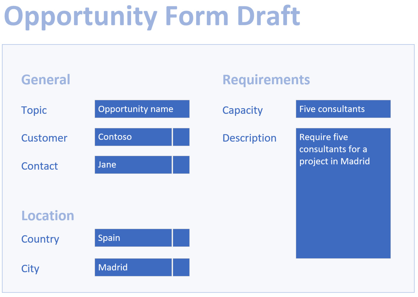
Figure 8.6 – Example Model-Driven App form design
Form designs go through multiple iterations of change, making simple wireframe diagrams ideal for quick live updates during workshops. Their purpose is to illustrate the form’s structure, the fields that will be presented to users, and the type of data that would be entered during the normal use of the form, including sample data so that the viewer can visualize their use of the application.
Dashboard designs
Similar to form design, Model-Driven App dashboards also benefit from simple upfront designs, which may be created during the design workshops. Solution Architects help stakeholders and product owners craft dashboard layouts that contain just enough information for the viewers to understand what the result will allow them to see on those dashboards.
The Solution Architect, in collaboration with the stakeholders and product owners, can quickly adjust the contents, layout, and structure of these dashboards using a graphical design tool.
The implementation team can then use these dashboard designs to build the solution. The following diagram illustrates a simple dashboard design that might be used during an interactive session with the project stakeholders:
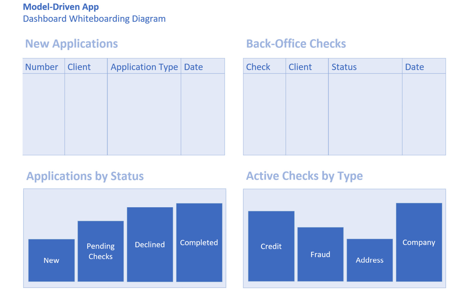
Figure 8.7 – Example Model-Driven App dashboard design
Now let us understand the business process flow designs.
Business process flow designs
Business processes form a key part of Model-Driven Apps. As a Solution Architect, you will review the requirements and process models captured in the earlier sessions and create designs for how these will be implemented within a Power Platform application.
Depending on the implementation, this may take shape in the form of business process flow designs or general process automation processes. The decision to use business process flows will often be driven by the need for users to visualize a multi-stage journey. If the user could benefit from such a view, business process flows are an ideal solution as data is relatively easy to configure.
The following diagram illustrates how a process can be broken down into stages and can be then built into a business process flow:
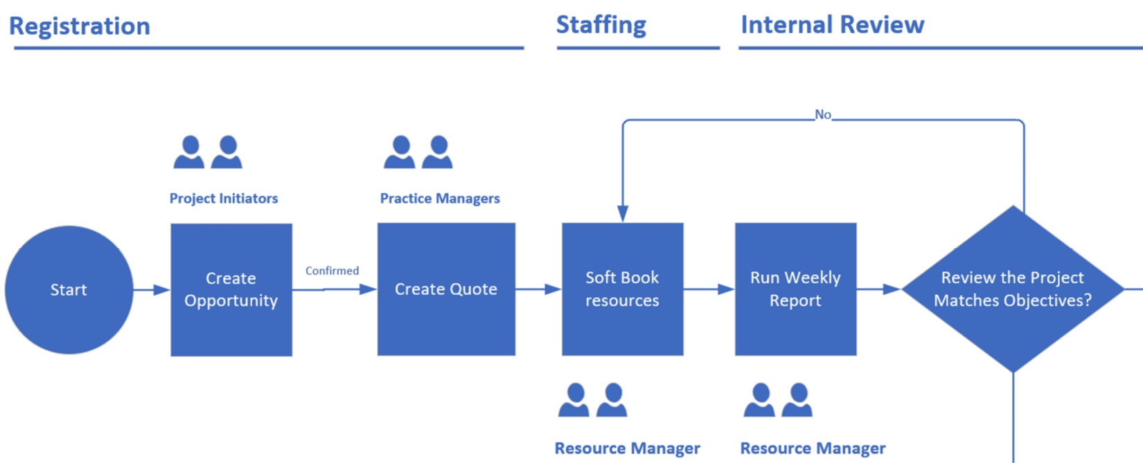
Figure 8.8 – Model-Driven App business process flow design breakdown
Solution Architects work with stakeholders during the design phase to develop the ideal process flows, moving the various tasks, personas, and data points into place. During an interactive session with stakeholders, everyone can agree on the flow of the process and the sequence of events that the system users will follow.
Once agreed, the implementation team can use these design diagrams to build the various processes within the Model-Driven App.
State machine designs
Specific Model-Driven App processes benefit from status management. Depending on the complexity of the process, and the status transitions involved, it may be helpful to create a state model diagram or a state machine design.
Let’s see some advantages:
- State machine diagrams define the transitions between the statuses of record or overall process, allowing the Solution Architect to visualize the various paths a process may go through.
- Any exceptions that need to be handled as part of the implementation become apparent when visualizing the status flow.
- The state machine diagrams also provide stakeholders with a visual cue for how their data will transition throughout the lifetime of a business process journey.
- State machine diagrams are vital components of any state-driven application. They should be drafted early in the process, feeding into all other Model-Driven App designs as a base status structure.
The following diagram illustrates a state machine diagram for a customer onboarding process:
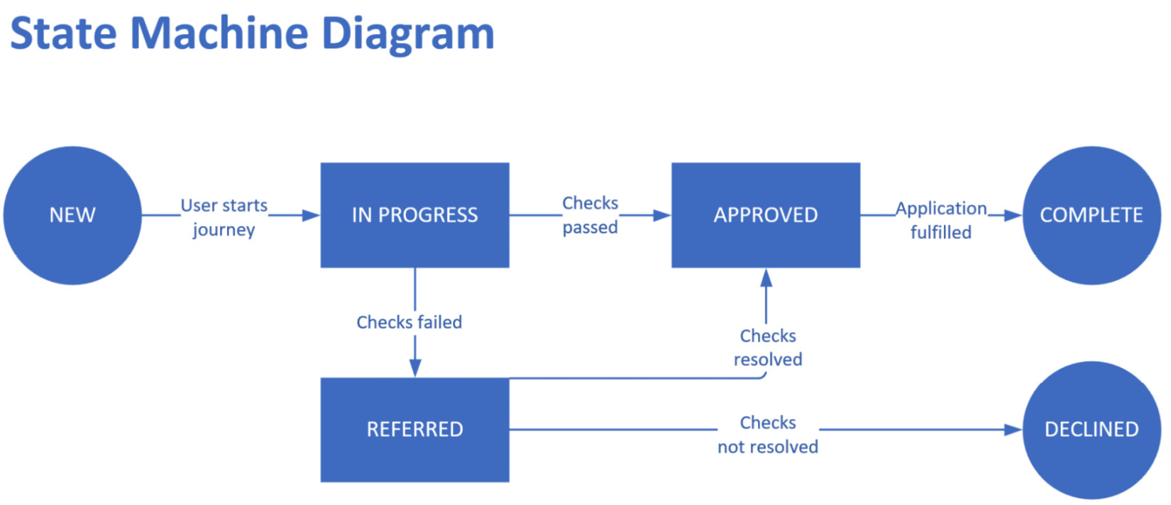
Figure 8.9 – State machine diagram for a customer onboarding journey
The implementation team can then work off the state machine diagrams and build the necessary state transitions, triggers, and automation logic to fulfill the design.
Designing Model-Driven Apps using additional components
When designing Model-Driven Apps, Solution Architects consider additional components that can be leveraged within forms and dashboards.
Canvas Apps may be embedded within Model-Driven App forms to present a rich user interface that would not usually be possible using the standard form components. Therefore, your design will include Canvas Apps where a requirement demands it.
The various designs, artifacts, and documents that are created as part of the Model-Driven App design process can then be used within the implementation tasks. It is often useful to include the designs (or a reference to them) in the implementation team’s task management tool. This means that team members can work directly off these designs and create a solution that matches the vision created by the Solution Architect.
Canvas Apps design
During the Canvas App design phase, it is often helpful to create mockups or wireframes of what the users would see and the components they will interact with, so that a non-functional UI prototype can be rapidly developed without opening the editor.
Canvas Apps rely on connectors to interact with data sources and APIs to perform the various tasks a user may carry out on the user interface. As a Solution Architect, you will identify the data sources and connectors that will be used within the application. Power Platform implementations tend to use Dataverse as their primary data source. Therefore, the Canvas App design would include the tables the user would access.
Canvas Apps provide a rich set of logic building blocks that can be used to present users with a user interface that fulfills complex tasks on their behalf. A Solution Architect needs to identify the best location for business logic. Complex business processes are often best kept within the Dataverse and Power Automate layers rather than being built within Canvas Apps. This allows business logic to be reused within other Power Platform applications.
The following diagram illustrates an example UI design where the user interface transitions through three steps, allowing the user to enter information at each stage within a Canvas App:

Figure 8.10 – Example Canvas App UI design
Canvas Apps can also be included within Teams channels to provide a rich UI through which users can interact with an application and the data sources that are attached to it. When designing Canvas Apps, you can identify use cases where they may be embedded into the Teams application and create a design for a Canvas App that lends itself to be placed within a messaging tool.
The visual nature of Canvas Apps lends itself to graphical UI and UX design. The diagrams you create during the design sessions with stakeholders can then be used by the implementation team and become the blueprint for the application user interface.
Designing Power Pages (previously known as Power Apps Portals)
When designing Power Pages solutions, you will be building design documentation that the implementation team will use. The design documentation needs to be of sufficient detail so that the consultants and developers can proceed with the configuration and development tasks.
Power Pages have multiple implementation paths. From wizard-driven journeys using Advanced Form steps to single-page applications (SPAs), they provide a base framework for public-facing websites.
Key Portal design considerations
There are three key areas that Solution Architects should consider when designing a Power Pages application:
- User authentication and security:
Users may access Power Pages either in an authenticated or anonymous state. One of the key decisions of a Portal design will be to define whether users will require authentication to access certain application features and the type of authentication that will be used. The authentication method selected will impact the overall design solution and will be carefully chosen at the design stage.
The authentication options that are available for Power Pages at the time of writing are as follows:
- Azure AD (OpenID Connect)
- Azure AD (SAML 2.0)
- Azure AD (WS-Federation)
- Azure AD B2C (OpenID Connect)
- AD FS (SAML 2.0)
- AD FS (WS-Federation)
- Microsoft (OAuth 2.0)
- LinkedIn (OAuth 2.0)
- Facebook (OAuth 2.0)
- Google(OAuth 2.0)
- Twitter(OAuth 2.0)
- Local authentication (deprecated)
Reference Documentation
Please refer to the Power Apps Portal/Power Pages authentication documentation at https://docs.microsoft.com/en-us/powerapps/maker/portals/configure/configure-portal-authentication for more information.
- User interface:
Power Pages are graphically driven websites that are configured via their corresponding administration app. Portals may be SPAs or multi-page applications with drill-down lists, multi-step journeys, and more. Whichever option you select, you will want to create a UX wireframe that illustrates the components to be built.
The wireframe designs will also be useful artifacts during stakeholder discussions and uses. Non-technical individuals will be able to understand how the Portal will be built thanks to visual cues in your user experience designs.
The following diagram illustrates an example Portal UX journey:

Figure 8.11 – Example Power Pages journey design
- Portal configuration versus development:
Power Pages provide extensive configuration capabilities thanks to their various UI-building tools. Forms are usually built using the same editor as Model-Driven Apps. During the design phase, you will review the requirements and use case scenarios to identify areas that may require custom development. Favoring configured solutions versus custom development expedites implementation and keeps maintenance costs low.
There are instances where creating coded solutions is the best option. When a portal requires custom development, you will aim to create design and coding guidelines for developers to follow. Portal custom development may be carried out using one or more of the following options.
- Power Pages custom development options:
- JavaScript: Client-side code that extends the functionality of forms or pages.
- Liquid Templates: Server-side logic is used to retrieve data from DataVerse and extend the standard Portal page’s rendering capabilities.
- Power Control Framework: These are now available within Power Page forms and extend the standard field capabilities.
- Dataverse Plugins: These use the .NET development language.
Custom development and .NET plugins and Workflow Code Activities, in particular, may be considered as options when the standard Portal functionality does not fulfill the project requirements, and the requirements may not be adjusted to work with the out-of-the-box feature set:
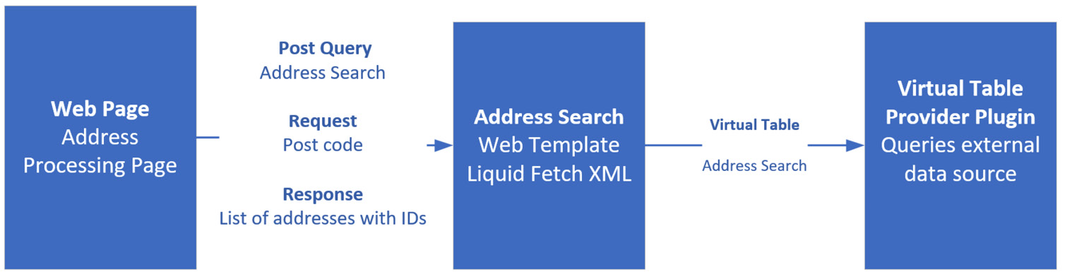
Figure 8.12 – Example Power Pages custom development design – browser to server interaction
The preceding diagram illustrates an example design that includes interaction between the browser, the Portal application servers, and custom plugin components for an address search page.
Roadmap for Canvas and Model-Driven Apps
Canvas Apps, Model-Driven Apps, and Portals have a roadmap of features published regularly. Solution Architects reference the application’s roadmap, including features that are coming soon and would be beneficial to the project. Similarly, any capabilities that are due to be deprecated would also be taken into account so that they can be excluded from the design to prevent refactoring and expensive reimplementation in the future.
Reference Documentation
The Power Platform and Dynamics 365 roadmap can be found at https://powerapps.microsoft.com/roadmap/.
Power Automate design
Power Automate provides a rich business process automation framework through which consultants create complex business processes via a drag-and-drop user interface. It provides a no-code alternative to custom development.
During the design phase, Solution Architects will concern themselves with the following areas.
Triggers
Cloud Flows use various types of triggers to initiate the execution of business processes. Solution Architects review the requirements and create automation designs that specify the types of triggers that will be used by the implementation team.
The three types of Cloud Flows triggers are as follows:
- Automated Flows: The process is triggered by an event such as a Dataverse row being added or an email being received.
- Instant Flows: The process is triggered by the user pressing a button on a form.
- Scheduled Flows: The process is triggered at a specified frequency (for example, every day at 00:00 hours)
Typical Power Platform Cloud Flows tend to use Dataverse table actions as a trigger, initiating an automation process when a record is created, updated, or deleted, or when a custom action is executed. It is important to define project best practices when Flows are created using trigger settings that are appropriate for the project’s needs.
Defining retry strategies and concurrency requirements for Cloud Flow triggers will help result in a consistent implementation across the project’s business processes, improve resilience, and reduce unexpected behaviors caused by race conditions.
The Dataverse triggers that are available within Cloud Flows are as follows:
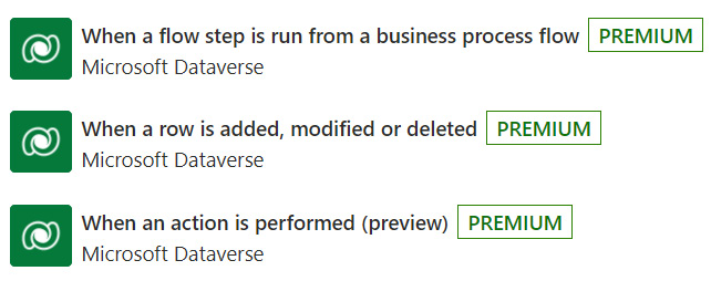
Figure 8.13 – Dataverse Cloud Flow triggers
Dataverse triggers default to retrying the execution of a Cloud Flow four times. While this may be sufficient for many applications, there are instances where the execution of a process is critical to the business. In those instances, the retry policy will need to be changed from its default settings, as shown in the following screenshot:

Figure 8.14 – Default Cloud Flow configuration for Dataverse triggers
Upgrading the Trigger retry policy settings for critical processes will help ensure the Cloud Flow is executed when the system is under load (for example, during peak periods of Dataverse API usage).
The following screenshot illustrates a Cloud Flow trigger that’s been configured to retry every 30 seconds up to 90 times:
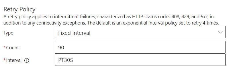
Figure 8.15 – Cloud Flow trigger set to retry every 30 seconds up to 90 times
Under certain circumstances, an exponential trigger retry policy will provide an even more robust Cloud Flow implementation strategy. The policy illustrated in the following screenshot will retry the trigger up to 30 times every 30 seconds, and the retry frequency increases exponentially up to 1 hour:
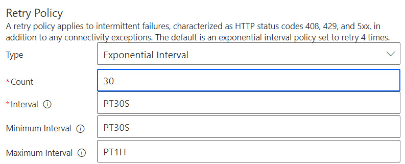
Figure 8.16 – Cloud Flow trigger set to use an exponential retry policy
In addition to the retry policies, the level of parallelism that’s used by Cloud Flows executions may be controlled via the trigger settings. Multiple instances of a Cloud Flow may be triggered in parallel by default. The default setting benefits general automated processes, as parallel processing results in higher execution performance. There are instances where having a Cloud Flow being triggered multiple times in parallel may cause unexpected results.
During the design phase, Solution Architects identify processes that may not be executed multiple times in parallel. A typical example is a potentially long-running process that executes on schedule every 30 minutes. If having multiple instances of the process running at the same time is likely to cause unexpected results due to two processes reading and writing to the same data, the concurrency of the Cloud Flow should be set to 1.
Equally, if there is no benefit to multiple instances of a process running in parallel, changing the Cloud Flow’s degree of parallelism to 1 would ensure only one instance may run at any one time. The following screenshot shows the trigger’s concurrency control parameter set to run only one instance of a Cloud Flow at a time:

Figure 8.17 – Cloud Flow trigger will run only one instance at a time
Cloud Flows may be triggered by a wide range of events, such as HTTP requests, SharePoint actions, and more. As a Solution Architect, you will identify the best trigger to fulfill a business requirement and create a blueprint for the flows that will be built by the implementation team.
Common actions
Power Automate Cloud Flows have a wide range of actions available. Power Platform Solution Architects are aware of the Dataverse actions available to understand the framework’s automation capabilities within the context of Model-Driven Apps, Canvas Apps, and Portals. The Dataverse actions that are available within Cloud Flows at the time of writing are as follows:
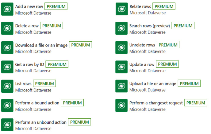
Figure 8.18 – Dataverse actions available within Cloud Flows
Power Platform Solution Architects also consider actions relating to Outlook email notifications and SharePoint document management events in the Power Automate designs.
Power Automate Reference Documentation
For more details on Power Automate’s triggers, actions, and capabilities, please go to https://docs.microsoft.com/power-automate/dataverse/overview.
Power Automate limits
Power Automate Cloud Flows are bound by API limits. Solution Architects take these limits into account so that the normal function of this solution is unaffected by their enforcement and compliance with purchased capacity.
Power Automate designers are also conscious of the Dataverse API limits when creating Cloud Flows, especially those expected to transact a high number of Dataverse API requests. The Dataverse API has a 5-minute sliding window, within which a user may perform a maximum number of API requests before the calling client is throttled. Power Automate handles throttling responses to a certain extent. However, the Cloud Flow design will need to consider the retry policy on Dataverse actions to ensure the process does not fail under load.
Cloud Flows are subject to three key types of limits:
- Limits for automated, scheduled, and instant flows:
Cloud Flows are subject to several design limits (for example, the maximum number of action steps, variables, and parallel concurrent executions) and operational limits (for example, actions per 5-minute sliding window, content throughput per 5 minutes, and 24 hours).
Solution Architects are aware of these Power Automate limits and must consider whether Cloud Flows is a suitable solution, depending on whether the projected usage and throughput required from the process falls safely within the limits of the Power Platform framework.
Reference Documentation
For more details on limits for automated, scheduled, and instant flows, please go to https://docs.microsoft.com/power-automate/limits-and-config.
- Request limits and allocations:
Cloud Flows consume Power Platform requests on every action they perform, including conditional statements, variable initialization and updates, and other action steps within the Cloud Flow designer, except for the Scope action step. The user request limits vary, depending on the license being used to execute the Cloud Flow. Power Automate’s per-flow plan has a much greater number of Power Platform requests allocated per 24-hour period than the Power Platform and Dynamics 365 user licenses.
During the design phase, Solution Architects will consider how the Cloud Flows will be executed and the most optimal licensing strategy for the processes, and then design accordingly. A Power Automate per-flow license would be suitable for use when a specific Cloud Flow is expected to use a large number of Power Platform requests on a given day.
Note that Power Platform request consumption is measured at its peaks. For example, if a process uses 10K requests per day, except for the first day of the month, where it uses 100K Power Platform requests, the licensing strategy will have to cater to the peak. In this scenario, the Cloud Flow will require sufficient capacity to consume 100K Power Platform requests per day.
Solution Architects carefully consider the projected Power Platform API request consumption for specific processes and the solution as a whole to preempt high-cost licensing situations. The design will consider the license limits and guide the decision to use the Cloud Flows or an alternative component that, while less configurable, is not bound by the same Power Platform request limits.
Reference Documentation
Please refer to the following documentation for the latest Power Platform license user request limits: https://docs.microsoft.com/power-platform/admin/api-request-limits-allocations.
- Service protection API limits:
Like any other client communicating with the Dataverse API, Cloud Flows are bound by service protection API limits put in place to safeguard the availability and performance of the platform for all users.
Of particular interest is the 5-minute sliding window API request limit. Cloud Flows that exceed these limits when communicating with Dataverse will receive a throttling response, and their function will be impacted.
Solution Architects take care to design a Cloud Flow implementation strategy that considers the projected Dataverse throughput that’s expected from normal and peak processing times. The most appropriate solution for a particular task is selected on that basis. For example, suppose a process requires two million records to be imported into Dataverse within 1 hour. In that case, a Cloud Flow will likely be flagged for throttling due to the high volume of API requests and the consumption of Power Platform requests. An alternative solution, such as a bulk data import, may be better suited for the large volume of data to be imported.
Reference Documentation
For more details on service protection API limits, please go to https://docs.microsoft.com/powerapps/developer/data-platform/api-limits.
In short, Solution Architects create Cloud Flow designs that carefully consider their usage, the consumption of Power Platform requests, and limit consumption to ensure the normal production usage by Cloud Flows is within the purchased limits.
Monitoring
Power Automate and Cloud Flows include monitoring tools where administrators review failed processes and usage statistics. The Power Platform Admin Centre provides an overview of Power Platform usage, as shown in the following screenshot:
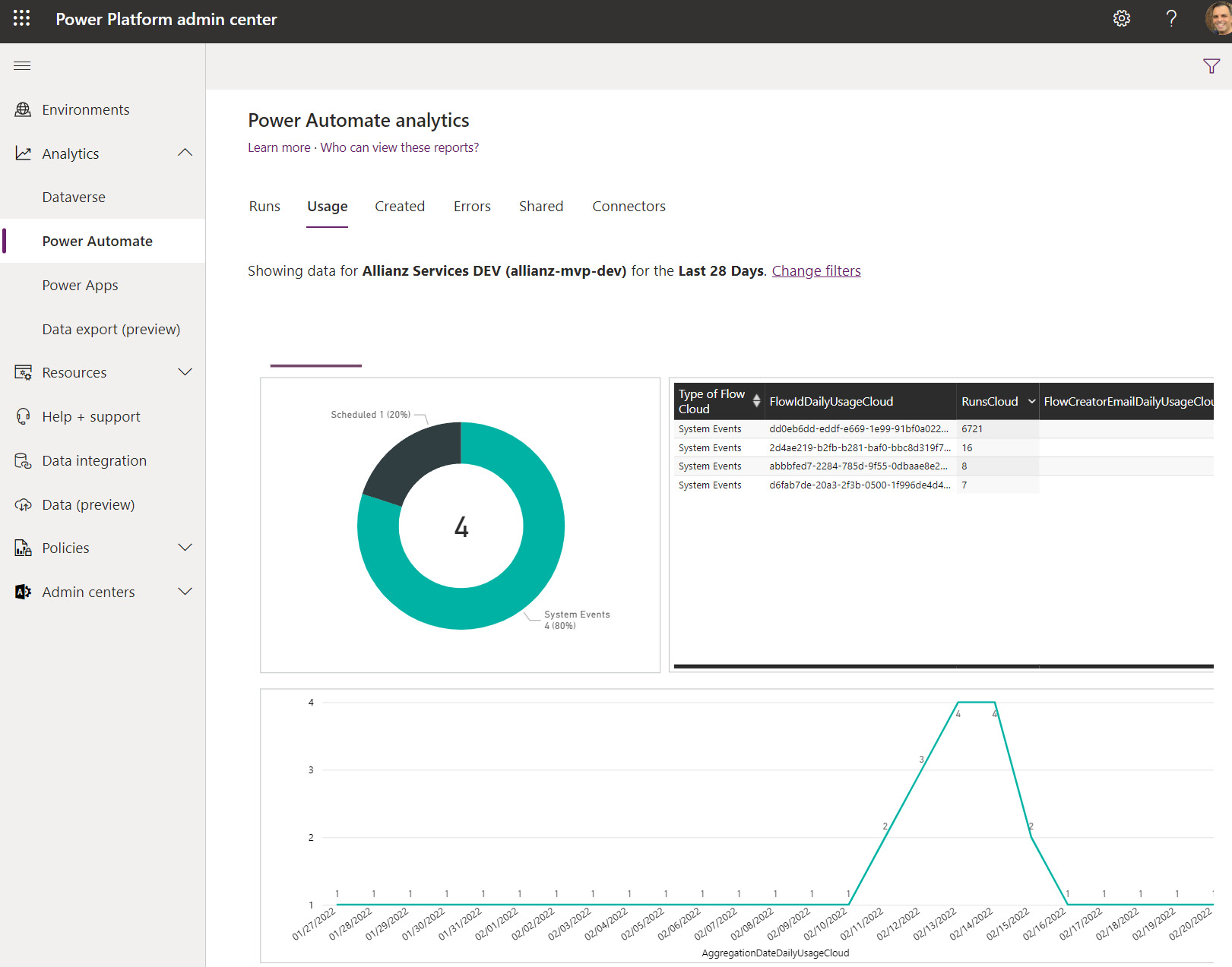
Figure 8.19 – Power Platform analytics overview page
The Power Platform request consumption may be viewed on a per-flow basis via the Cloud Flow analytics page. Solution Architects use this page to review the consumption of requests and make projections on the expected capacity and licensing required for the system to perform in a production environment (and other development and test environments):
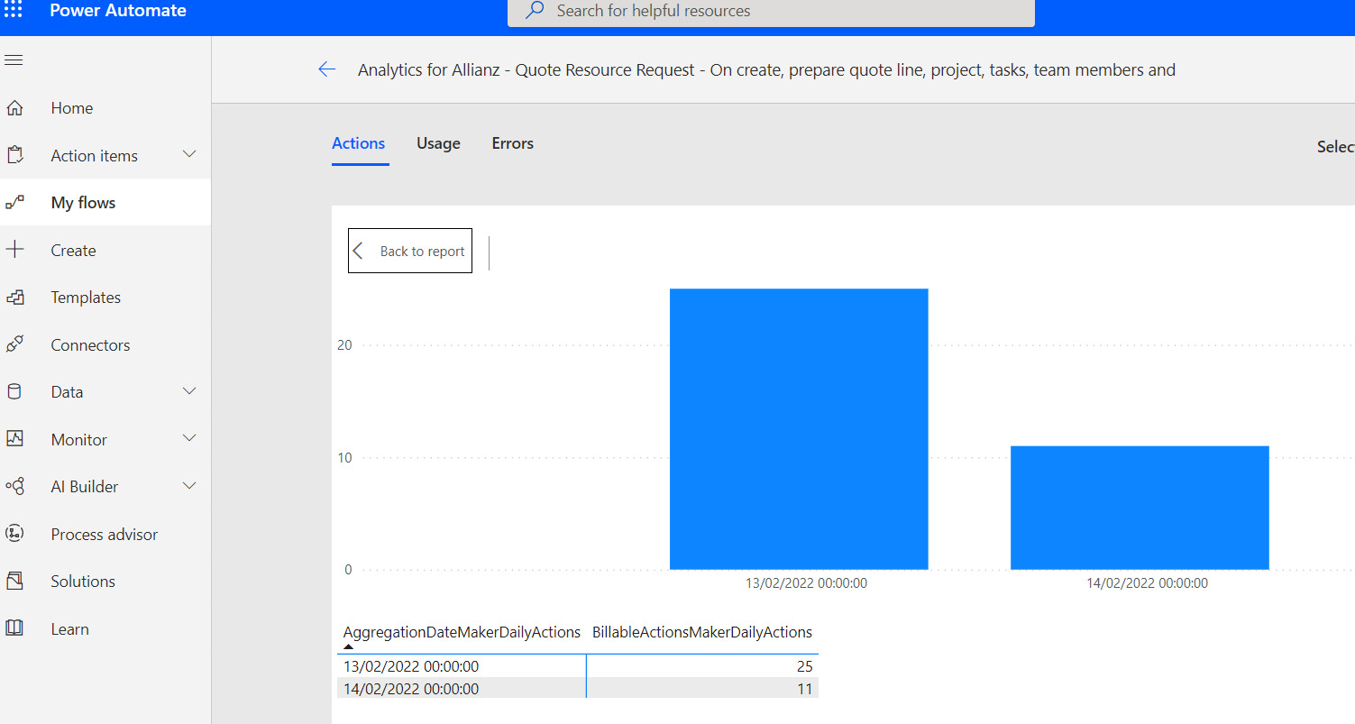
Figure 8.20 – Cloud Flow analytics page
In addition to the built-in Power Platform monitoring tools, day-to-day operations may be facilitated by implementing an error logging strategy. Exceptions during Cloud Flow execution may be caught, recorded, and surfaced within a Model-Driven App dashboard. This kind of logging and monitoring strategy tends to be easier to use than the built-in Power Platform tools and makes the system easier to use and maintain.
Resilience
An optimal Cloud Flow implementation carries out its functions with minimal administration overhead. Solution Architects create designs that include retry strategies that prevent processes from failing unnecessarily when transient exceptions occur. Power Automate includes a built-in retry strategy within many of its actions, specifying the number of retries to carry out when an error occurs and the delay between each retry.
By default, similar to the trigger retry policy mentioned in the earlier sections of this chapter, the default Cloud Flows configuration retries actions up to four times. As a Solution Architect, you will set out the retry strategy for critical actions (for example, if you’re attempting to communicate with a critical API, the default policy will be changed to 30 retries every 10 seconds).
Solution Architects design the blueprints for Cloud Flows with exception handling in mind, which may be in the form of a logical path that’s followed when an exception or error occurs. An exception handling catch-all process can create log entries in Dataverse, alerting system administrators that an error has occurred and that the process may require remedial action.
Solution Architects aim to design Power Automate processes that are as resilient as possible within the project’s technical and commercial constraints.
Business process flow management
Cloud Flows can interact with business process flows that are presented within Model-Driven Apps forms.Auto-progressing to the next stage of a business process is a typical automation task that makes the user’s life easier, reduces the scope for user error, and may be implemented using Power Automate.
Conclusion
In this section, you learned about the various items you will need to consider when designing Power Platform applications. You will use these techniques and tools to design solutions that add real value to an organization, are easy to build, and are cost-effective to maintain.
Facilitating understanding through descriptive visual designs
Power Platform solutions are often visual, presenting rich graphical user interfaces to back-office staff and clients. The tools that are used to configure and build Power Platform applications are also often visual. Solution Architects often benefit from using visually descriptive designs to represent a Power Platform solution.
These are some of the benefits of a visual solution design strategy:
- Brings non-technical users on board:
A picture speaks a thousand words. Visual designs give stakeholders and project owners a clear view of how the system will be built, in a format they can understand. Due to this, they are more readily brought on board and are more likely to accept your vision of a Power Platform future.
- Facilitates presentations and workshops:
Visual designs are powerful tools during sessions with stakeholders and users, allowing you to quickly adjust system areas in front of their eyes, which would otherwise take hours or days to change. The visuals facilitate a discussion with the audience and allow you to reach the desired result, capturing a solution that best solves a customer’s problem with the fewest iterations.
- Easy to onboard new team members:
Visual designs allow new team members to get up to speed much quicker than having to read lengthy textual documentation. They can also follow your instructions faster, resulting in shorter implementation times.
As a Solution Architect, you will seek to use the visual design diagrams illustrated in the earlier sections of this chapter to boost the design sessions and implementation phase’s productivity.
Defining user experience prototypes for customer-facing and internal applications
Power Platform implementations with substantial customer-facing user interfaces benefit significantly from early user experience (UX) prototypes, allowing stakeholders and potential users to try out an application before it is built. This activity has various benefits.
Benefits of UX prototypes
Let’s look at some of the benefits of the UX prototypes:
- An early trial of the application’s UX:
Creating a UX prototype takes much less time than building a Power Platform application. Users that try out a mocked-up application version using a UX prototype can provide crucial feedback early on in the project that may change the course of the implementation for the better.
- Reduces implementation costs:
The ability to review an application with user feedback reduces overall implementation costs, as the solution is steered toward a successful outcome early on. The number of build interactions and releases is reduced.
Leveraging the design strategies and visualizations presented in the earlier sections of this chapter will help an organization and implementation teams by providing a set of living documents that are easy to understand and update. They, in turn, will be able to implement the solutions described in the design documentation more effectively and yield a better solution in a shorter time.
Designing data migration strategies
A migration strategy provides a clear understanding of the activities, steps, and impact of moving from one system to another. Solution Architects design migration strategies by considering the following factors:
- The volume of data to be migrated
- The structure and format of the data to be migrated
- The route to access the source data
- The destination for the data
- The level of data processing required by the data
- The impact of potential API throttling
- The production downtime required
In Chapter 3, Discovery and Initial Solution Planning, high-level migration estimates and efforts were discussed. This section expands on this preliminary analysis to flesh out the complete migration strategy for a Power Platform implementation.
When designing a migration strategy, Solution Architects consider the capabilities that are available within the Power Platform feature set, which include the following:
- Data Flows
- Power Automate
- Excel imports
Each of these tools provides varying throughput capabilities and lends itself to different use cases. As a Solution Architect, you will select the most appropriate data migration route.
Note
While several third-party tools are available that import data into Dataverse, for conciseness, we will consider the toolset that’s available within the Power Platform framework within this book.
Having reviewed the factors in migrating a solution, the resulting analysis may be consolidated in a migration strategy summary. The following table provides an example migration strategy analysis that’s designed to move case management data from legacy systems onto Dataverse for use within a Model-Driven App:

Table 8.1 – Example data migration strategy for case management data
Once the data migration factors are understood, you can design a detailed data migration strategy.
Defining the application life cycle management process
Application life cycle management (ALM), which was introduced earlier in this book, is a set of disciplines through which Power Platform projects can be defined, implemented, deployed, and operated through a controlled framework. Solution Architects define ALM processes for a Power Platform implementation, enabling the orchestration of project tasks, build activities, testing, deployment, and implementation review.
The following diagram illustrates the activities and areas that are covered by Power Platform ALM:

Figure 8.21 – Power Platform ALM
An effective Power Platform ALM strategy can be created by following these steps:
- Plan an environment strategy:
Typical Power Platform implementations benefit from having a minimum of three environments: a development environment, a test or QA environment, and a production environment. The use of a pre-production environment should be considered for mission-critical services.
- Set up an Azure DevOps project:
This will be the base of operations for your Power Platform implementation. It is where the requirements, tasks, and issues will be managed and distributed across the team members.
This will also be the home of the source control repositories. As part of the initial source control setup, Solution Architects define the branching strategy and pull request process (for Git-based source control) for the team members to use.
- Create a Power Platform solution and publisher:
As a Solution Architect, you will be well-positioned to define the Power Platform solution strategy that the team members will use. As a minimum, the project will use a base solution, where the configurations and customizations will be placed. Additional apps and flows may be stored within the solution for later deployment to the test and production environments.
- Create a development export pipeline:
This will be the Azure DevOps pipeline that will extract the Power Platform solution from the development environment and place it in source control for later deployment. Automated tests may also be included in the pipeline tasks to ensure the health of the solution before its release.
- Build the Power Platform solution:
This is where the actual project implementation takes place – that is, the configuration of Dataverse, Model-Driven Apps, Canvas Apps, Flows, and plugins. All these activities result in components that are added to the Power Platform solution.
- Create a deployment pipeline:
The deployment pipeline takes the solutions and data that have been exported from the development environment and imports them into the target environments. This may be either an automated process or manually triggered on-demand, depending on the release strategy you decide for the project.
- Grant access to users:
Once the solution has been deployed, the final step is to assign licenses and security roles to the users.
With the Power Platform ALM process in place and in full swing, the project is in a good position to deliver the solution.
Summary
In this chapter, you learned how to create a Power Platform Solution Architecture topology that reflects the organization’s business needs. You have gained a thorough understanding of the various items you should consider when designing Power Platform components and the benefits of visual design.
In the next chapter, you will learn how to translate complex business requirements to visual data models, design extensible Power Platform ERD diagrams, and define core reference data models. You will also learn about factors to consider when integrating with or exporting external data.