Chapter 2. Working with the SAE AADL
With the AADL, you capture the architecture of embedded systems as architectural models that provide well-defined analyzable semantics of its runtime architecture. The creation of these descriptions encompasses identifying and detailing software and hardware components and their interactions in the form of interface specifications (component types) and blueprints of their implementation (component implementations) and organizing them into packages. These packages effectively represent libraries of component specifications that can be used in multiple architecture models, can be authored and maintained by different modelers, and may be version controlled. Packages have public and private sections in support of information hiding. Public package sections contain specifications available to other packages. You use the private package section to protect details of component implementations you do not want to expose to others. AADL models may also include property sets through which you introduce new user-defined properties to the AADL model.
For software components such as threads, processes, and data, you define their runtime characteristics including execution times, scheduling, and deadlines. In addition, you declare other code related information such as execution code size, source code language, source code file names, and source code size.
Threads (execution paths), data, and processes (representations of compiled code and data) are the principal runtime software abstractions within the AADL.
In describing hardware, you define execution platform components such as processors, memory, and buses, and characterize them with relevant execution and configuration properties. For example, in defining the execution hardware for a system, you declare the processors that execute threads, memory that stores code and data, and buses that provide physical connections between hardware components. The values of properties associated with these components are used to define characteristics such as processor speed, memory word size, etc. In addition, you can define devices to represent interfaces to a system’s operational environment such as sensors and actuators.
Processors, memory, buses, and devices are the hardware abstractions within the AADL. They provide the execution environments, physical communication paths, and external interfaces for a computing system.
To complete the architectural description, you define a fully specified system implementation by integrating all of a system’s composite elements into a single component hierarchy. This hierarchy establishes all of the interactions among the components and the architectural structure required to define an executable system. These encompass data and event exchanges and the physical connections among components as well as the assignment of software to hardware (e.g., where data and execution instances are stored, where software executes, and the hardware supports data and event transfer). When you instantiate this top-level system implementation you get an AADL instance model that is a mirror image of the system you are modeling. This instance model is the basis for analyzing operational properties of your system. Throughout the development of an architectural model, you can conduct extensive analyses of consistency and compliance with requirements. These analyses range from syntactic compliance and basic interface data consistency checking to rigorous assessments of quality attributes and behavior. For example, using AADL formal representations and specialized extensions, you can investigate properties such as data latency, bandwidth, scheduling, and dependability.
2.1. AADL Models
Central to an AADL model are component type and implementation declarations, organized into packages (see Section 4.4.1). In a component type declaration, you define the category and interfaces (features) of the component. This corresponds to a specification sheet for a component. In a component implementation declaration of that type, you define the internal structure of the component (i.e., its constituents and their interactions). This corresponds to a blueprint for building a component from its parts. In these declarations, you specify the properties required to define fully a component’s runtime characteristics. These properties may be one of the predeclared properties in the AADL standard, properties introduced through standard annexes for specific analyses, or user-defined properties that you have introduced through additional property sets. Collectively, these declarations (a type plus an implementation) define a pattern for a component. Component types and implementations are referred to as component classifiers.
2.1.1. Component Categories
Components are grouped into application software, execution platform, composite, or generic (non-runtime specific) components. These are summarized in Table 2-1.
Table 2-1. Component Categories


2.1.2. Language Syntax
The AADL is a formal declarative language described by a context-free syntax [AS5506A].1 In the language, names and reserved words are case insensitive. In our examples, reserved words are shown in lowercase boldface type by convention. Listing 2-1 shows an example AADL declaration for a package controllers containing a process type declaration in its public section. There are two features defined for the process speed_control: an in data port and an out data port. These features define data input and data output interfaces for the process type. An end statement terminates the package and process declarations. Blank lines shown in the example are optional. They are included to improve readability.
Listing 2-1. Example AADL Declarations
package controllers
public
process control
features
input_speed: in data port;
output_cmd: out data port;
end control;
end controllers;
2.1.3. AADL Classifiers
Component types and implementation declarations are classifiers. You reference classifiers by their name to establish an occurrence (an instance) of the pattern that they describe. These references are made within individual textual statements contained within type and implementation declarations. For example, within a type declaration a single textual declaration is used to declare that a component has an in data port with the name input_speed and the type of the data that passes into the component through the port is identified by referencing a data type (e.g., speed_data). A sample component type declaration is shown in Listing 2-2, which includes an in data port declaration that references speed_data.
Listing 2-2. Sample Component Type Declaration
process control
features
input_speed: in data port speed_data;
toggle_mode: in event port;
throttle_cmd: out data port throttle_data;
error_set: feature group all_errors;
flows
speed_signal_path: flow path input_speed -> throttle_cmd ;
properties
Period => 20 ms;
end control;
As another example, consider the subcomponent declarations within the partial implementation declaration shown in Listing 2-3. Note that this is an implementation of the process type control as reflected in its name control.speed. In this example, the subcomponent read_speed is declared as an occurrence (instance) of the thread component implementation (pattern) read_data.speed and the subcomponent control_laws is declared as an instance of the thread component implementation control.basic.
Listing 2-3. Sample Component Implementation Declaration
process implementation control.speed
subcomponents
read_speed: thread read_data.speed;
control_laws: thread control.basic;
connections
c1: port input_speed -> read_speed.in_data;
c2: port read_speed.out_data -> control_laws.in_data;
c3: port control_laws.cmd -> throttle_cmd;
flows
speed_signal_path: flow path
input_speed -> c1 -> read_speed -> c2 ->
control_laws -> c3 -> throttle_cmd ;
end control.speed;
2.1.4. Summary of AADL Declarations
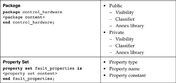
Table 2-2 summarizes the set of AADL declarations. The left column lists classifier (component type, component implementation, and feature group declarations), package, and property set declarations and a simplified example of each. The right column summarizes the structure and content of the declarations listed in the left column.
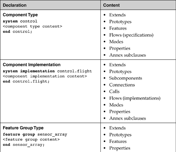
You can include up to seven sections within a component type declaration. These sections are shown in the order in which they are declared. One section is features, the section in which interfaces (e.g., ports) of a component are declared. The flows section allows you to talk about flow through a component without exposing the component implementation and attach properties such as latency or computational error to the flow. The modes section allows you to talk about operational modes of the component. The prototypes section allows you to parameterize the component type as a template and you use the extends construct to refine the component type template. You may also include a properties section within a type or implementation declaration. The properties section is where values are declared for properties associated with a component or feature group. You may also adorn many of the declarations listed in the column on the right (i.e., features, flows, modes) with property values. For example, when you declare a thread subcomponent you can assign a specific value of the Period property for that thread subcomponent. Annex library and annex subclause declarations enable you to extend the capabilities of the AADL language.
Component implementations consist of up to nine sections. The extends, prototypes, properties, and annex subclauses sections have the same role as for component types. You use the subcomponents section to specify the composition of the component from instances of subcomponents of various kinds by referring to their classifier. In the connection section, you indicate how subcomponents interact with each other and, through the features of the component type, with external components. The calls section outlines call sequences to subprograms from inside thread and subprogram implementations. The flows section details how a flow specification in the component type is realized as a flow through the subcomponents. The modes section may add mode transition information to modes specified in the component type or document component implementation specific modes.
In addition to component classifiers, there is a feature group type classifier. A feature group type defines a collection of component features. You indicate that a collection of connections may exist between two subsystems by grouping the features into a feature group for each and connecting them with a single connection. You can do so early in the modeling process as you define the subsystem architecture without detailing the individual features, and later provide the feature details by filling in the feature group type. You reference a feature group type when you declare a feature group within a component type declaration. This is shown in Listing 2-2, where the feature group error_set references the feature group type all_errors.
Packages allow you to organize component types, component implementations, and feature group types into a named group type. Packages represent separate namespaces for their content such that a component type is identified by its package name and its component type name (e.g., the component type pitch_control that is declared in a package controllers is referenced as controllers::pitch_control). One objective of grouping component specifications into a package is to allow different teams to develop a system, each team working on different parts independently. In this situation, a package may be used as a unit of version control.
A property set enables you to define new properties and property types in a separate namespace. These properties are identified by their property set name and property or property type name. This is especially valuable in customizing a description and in extending analyses (e.g., adding a specialized security level property to conduct a system-level security analysis). Property sets are not declared inside packages, but separately as part of an AADL model.
2.1.5. Structure of AADL Models
You distinguish between the structure of a system architecture and the structure of an AADL model. You use a hierarchy of interacting components to represent the system architecture. You use packages to organize component interface specifications (component types) and their blueprints (component implementations) into libraries such that a collaborating team can evolve the architecture model. You introduce new properties by grouping them into different property sets. In other words, an AADL model consists of packages and property sets. All AADL declarations must be contained within a package or property set declaration.
Package and property set declarations cannot be nested in any way (i.e., a package cannot be declared within another package or property set nor can a property set be declared within another property set or in a package). However, you can nest package names, similar to packages in the Java language. For example you can declare a package called sei::boats::gps.
Figure 2-1 presents the structure of AADL models. In the figure, rectangles represent declarations. The dashed arrow between a type and an implementation declaration indicates that the implementation belongs to the type pointed to by the arrow. The asterisk adorning the rectangles and the implementation links indicates zero or more occurrences. There may be multiple implementations associated with a single type and there may be types without implementations. In addition, while there may be multiple annex library declarations within a single package, there must only be one annex library declaration for each annex.

Figure 2-1. Structure of AADL Models
You can have a complete AADL model contained within a single file or have packages and property sets grouped into multiple files, even to the extent that there is a separate file for each package and each property set. These files can be worked on separately by different team members and can be version controlled. The partitioning of a specification into files is tool specific. For example, while not required by the standard, the Open Source AADL Tool Environment (OSATE) [OSATE] assumes that each package and property set is in a separate file. The AADL standard allows the AADL models to be stored in a database instead of a file system. In that case, there is no correspondence of packages to files.
2.2. System Specification and System Instances
A collection of AADL packages and optional property sets represent a system specification in AADL, referred to as AADL declarative model. It represents an architectural blueprint that describes the structure, properties, and connectivity of an embedded system.
A system instance model (or simply an instance model) is an instantiation of a system model using a system component implementation with a declarative system model as its root. You can create instance models of the whole system or of a particular subsystem of interest by choosing the appropriate system implementation declaration as the starting point. The component implementations of the declarative model are interpreted as blueprints to create and interconnect all the component instances of the system.
You use this instance model to analyze your system architecture and to drive the generation of its implementation using analysis capabilities built into or as extension of toolsets like OSATE, or through separate analysis via a standardized interchange representation. For additional information on model creation and validation tools, please see Chapter 15.
2.2.1. Creating System Instance Models
A system instance model represents an operational physical system that is generated from a fully specified declarative model. In a fully specified declarative model, the runtime architecture is represented to the level of threads and subprogram calls with application software components modeled as subprograms and data component types. In addition, a fully specified system includes processors to execute application code, memory to store application code and data, devices that represent the physical environment of the embedded application, and buses that connect these components.
AADL allows you to model your system to the level of fidelity appropriate for the development phase and analyses of interest. In other words, you may have created a partially complete model of the system in terms of major subsystems, or in terms of processes with or without threads. You can create an instance of such a partial model and analyze it. AADL allows you to create instance models of the whole system or instance models of any of the subsystems. You do so by choosing the appropriate system implementation as the root of your instance.
You use a tool like OSATE to generate the instance model. The generation is accomplished by first instantiating the elements that comprise a top-level system implementation and recursively instantiating their subcomponents and their subcomponents, and so on (e.g., systems to processes to threads). The resulting system instance model explicitly represents all of the requisite runtime aspects of the elements that comprise that system (e.g., binding of each thread to a processor, assigning required runtime properties to each element of the system).
2.2.2. AADL Textual and Graphical Representation
So far, we have focused on textual AADL. The well-defined semantics of AADL concepts is an important advantage of the AADL, especially for quantitative system architecture analysis. However, there are standard graphical representations that correspond to the textual representations of the elements of the AADL. These are defined in the SAE AADL standard [AS5506A]. Figure 2-2 shows a textual representation for a thread and its corresponding graphical representation. The graphical icon for a thread type is a dotted parallelogram as shown for the thread data_processing. Data ports are represented as small triangles that adorn a type icon, as shown for the data ports raw_speed and speed_out. The value of the Period of execution for a thread is contained inside an elliptical adornment at the top of the thread icon.

Figure 2-2. AADL Graphical and Textual Representations
In developing an AADL model of a system, either or both of these representations may be used. The preferred form is a matter of personal choice and is dependent upon the capabilities of the modeling tool you use. For example, you can create the initial structure of an embedded system architecture graphically and refine the model in textual AADL or rely exclusively upon the graphical interface for the creation and editing of AADL models and their corresponding textual representations. System instances are created and stored as system instance specifications (models) that are represented in XML. Analysis and code generation tools can operate on system instance models.
Throughout this book, we use the Open Source AADL Tool Environment (OSATE) as an example environment in our presentation of the AADL and its application in model-based engineering practices [OSATE]2. The capabilities described are not unique to the OSATE environment and the use of AADL does not require OSATE. As shown in Figures 2-3 and 2-4, OSATE supports graphical as well as textual representations of AADL and provides editing capabilities for each of them3. For example, you can create a component implementation declaration for a system graphically (see Figure 2-3) by selecting modeling elements from a palette and identifying component types from component libraries (packages). You then fill in properties for the components through a forms-based AADL property view. In other words, working with the graphical editor does not require detailed knowledge of the syntax of the AADL textual language in order to create initial models. You can then switch to the textual view (see Figure 2-4) and refine the AADL model textually when appropriate.
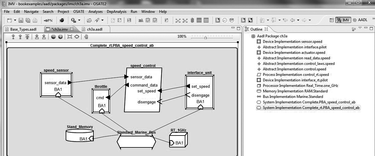
Figure 2-3. OSATE Graphical Representation
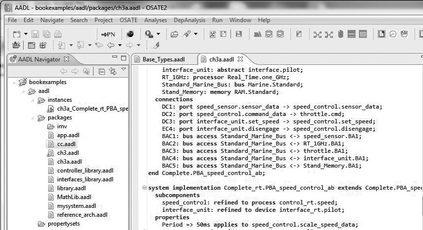
Figure 2-4. OSATE AADL Textual Representation
2.2.3. Analyzing Models
The well-defined semantics of AADL concepts allow various forms of quantitative analysis to be applied to AADL instance models. To create a system instance model for analysis, you can instantiate a partial or complete application system together with an execution platform declarative model. In this instance model, you can assign resource budgets in terms of CPU cycles and memory requirements to application subsystems and resource capacities to your execution platform. Given this data, you can analyze various bindings of application components to the execution platform and ensure that budgets do not exceed the platform’s capacity. You can also add flow specifications to individual subsystem components and end-to-end flows to the application system. Based on these flow specifications, flow analyses such as an end-to-end response time analysis can be performed. All of these analyses can be completed without a fully detailed system model. At the completion of an architectural development, a complete system instance model can be analyzed in extensive detail to assess compliance with required functional and quality levels.
Early in the system development process, it is desirable to have partially specified but analyzable system models. For example, you may want to represent an application system as a collection of interacting subsystems without providing details of their implementation (e.g., where subsystems are modeled only as abstract or system components). Many of these analyses can be conducted on partial declarative models. For example, you can check that all ports are connected, that there is data consistency between the ports involved in a connection, and that the resource budgets are within the specified capacities of the system.