Chapter 11. System Flows and Software Deployment
You have learned how to describe your system in terms of a hierarchy of components, and define the interaction between components in terms of connections. In this chapter, you will learn how to specify system level information. First, you will learn how to specify end-to-end flows through the system. This allows you to define critical information flows. They can reflect use scenarios and be the basis for system-level analyses. Second, you will learn how to bind the embedded application software onto the computer platform. This binding represents a deployment configuration, which is essential for any analysis that involves operational quality attributes, such as performance, security, or reliability.
11.1. Flows
Flows enable the representation and analysis of logical paths through an architecture. In support of flows, you can declare flow specifications for components. A flow specification defines a logical flow from a component input to a component output. These flows can be through ports as well as data access features and can represent any logical flow, such as data flow, control flow, or fault event flow. You can attach flow-related properties, such as latency or accuracy that can be used in end-to-end flow analysis without having to examine the implementation of the component. In component implementations you elaborate those flow specifications into flow implementations (i.e., as paths through its subcomponents). These paths start with the incoming feature of the flow specification, follow a sequence of connections and subcomponent flow specifications, and end with the outgoing feature of the flow specification. Similarly, you can define end-to-end flows. They start with the flow specification of a starting component, followed by a sequence of connections and other component flow specifications, ending with a component flow specification. The three types of flow declarations are summarized in Table 11-1.

You use flows to analyze important system characteristics. For example, you define a flow within a speed control system. This flow may originate at a speed sensor, traverse through the control elements of the system, and terminate at a throttle actuator. The total time between sending a speed value and the actuation of the throttle in response to that value can be analyzed. You identify the elements participating in the flow using flow declarations, assigning latency times to each of those elements using property associations, and calculating the total time for the complete flow path. The analysis compares this calculated time with the required time for the path from the sensor and the actuator.
11.1.1. Declaring Flow Specifications
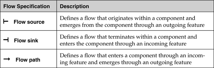
Flow specifications are contained within the flows section of a component type declaration and establish a component’s role in a flow. They identify the component as a flow source, flow sink, or flow path through the interfaces (component features) of the component. A flow source is associated with a component in which the flow originates and identifies the component feature (e.g., port, feature group, or parameter) through which the flow emerges. Similarly, a flow sink is associated with a component in which a flow terminates and identifies the component feature through which the flow enters. A flow path declares that a flow passes through a component from an incoming to an outgoing feature. Table 11-2 summarizes flow specifications and shows their graphical representations.
Table 11-2. Flow Specifications
The following box shows the template for the three flow specification declarations (flow source, flow sink, flow path). Flows are named elements. They are associated with a component such that flows originate from, terminate, or pass through a component via features declared within the flow specifications for the component.
name : flow source <exit feature> [{properties}];
name : flow sink <entry feature> [{properties}];
name : flow path <entry feature> -> <exit feature>
[{properties}];
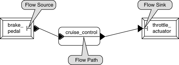
Listing 11-1 shows a partial specification for a simplified cruise control system with flow source, flow sink, and flow path specifications within component type declarations. The lower portion of the table includes a graphical representation of the flow specifications as well as the port connections between the components. Notice that the flow path brake_flow through the system component cruise_control has an out event data port as its origin and an in data port as its termination feature. Since a flow is abstract, it does not need to involve a single port type. A mix of port types is permitted (e.g., events, data, event data). Even in the case of a flow involving only data or event data ports, the data type associated with the ports can be different. However, the flow must be consistent with the direction of the information flowing through the features. In the case of data access, it must be consistent with write or read, while for ports it must be consistent with the port direction.
A component may have multiple flow specifications that define alternative roles for that component. This may include multiple flows through a single port as shown in Listing 11-1 for the event data port brake_event. Notice also that the flow paths brake_flow and control_flow in the system component cruise_control define two separate flow paths using the same incoming and outgoing ports. In the device brake_pedal, two flow sources are defined allowing the device to be a source for two distinct flows.
Listing 11-1. Flow Declarations Within a Component Type Declaration
device brake_pedal
features
brake_event: out event data port float_type;
flows
Flow1: flow source brake_event;
Flow2: flow source brake_event;
end brake_pedal;
--
system cruise_control
features
brake_event: in event data port;
throttle_setting: out data port float_type;
flows
brake_flow: flow path brake_event -> throttle_setting ;
control_flow: flow path brake_event -> throttle_setting ;
end cruise_control;
--
device throttle_actuator
features
throttle_setting: in data port float_type;
flows
Flow1: flow sink throttle_setting;
end throttle_actuator;
11.1.2. Declaring Flow Implementations
Flow implementations elaborate flow specifications of a component into a flow path through its subcomponents. Flow implementations identify the entry and exit features, connections, and subcomponents involved in a flow specification. For example, a flow source implementation for a component identifies the subcomponent from which the flow originates, all of the intervening subcomponents and connections that are involved in the flow within that component, and the feature through which the flow exits the component. A flow implementation may refer to only the entry and exit feature if no subcomponent exists or is involved in the flow.
Flow implementations are declared within the flows section of a component implementation. Patterns for each of the flow declarations are shown in the following box:
name : flow source <source path sequence> -> <exit feature.
[{properties}];
name : flow sink <entry feature> -> <sink path sequence>
[{properties}];
name : flow path <entry feature> -> <flow path sequence> ->
<exit feature> [{properties}];
The name used for a flow implementation must identify one of the flow specifications of the component. Path sequences are alternating connection names and dot-separated subcomponent/flow specification name pairs that are separated by the connection symbol (->) that start and end with the entry and exit features of the corresponding flow specification. The path sequences for flow sources, flow sinks, and flow paths are shown in Table 11-3.
Table 11-3. Three Types of Flow Implementations

Entry or exit features identify the external feature of a component through which a flow enters or exits that component. Property associations enclosed in brackets {properties} can be included in the declaration.
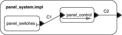
In Listing 11-2, you can see an example of a flow source implementation. A flow source disengage_flow is declared in the system type panel_system. Its corresponding flow implementation declaration is contained in the flows section of the implementation panel_system.impl. In this declaration, the flow originates within the system panel_switches (from the flow source disengage_flow); traverses the connection C1; passes through the system panel_control via the flow path disengage_flow_path; traverses the connection C2; and exits through the port disengage_out. This can be seen graphically in the lower portion of Listing 11-2. In the graphic, the flow arrows are displaced slightly from the actual flow path.
Listing 11-2. A Flow Source Implementation
system panel_system
features
disengage_out: out event data port;
flows
disengage_flow: flow source disengage_out;
end panel_system;
system panel_switches
features
disengage_out: out event data port;
flows
disengage_flow: flow source disengage_out;
end panel_switches;
system panel_control
features
disengage_in: in event data port;
disengage_out: out event data port;
flows
disengage_flow_path: flow path disengage_in -> disengage_out;
end panel_control;
system implementation panel_system.impl
subcomponents
panel_switches: system panel_switches;
panel_control: system panel_control;
connections
C1: port panel_switches.disengage_out ->
panel_control.disengage_in;
C2: port panel_control.disengage_out -> disengage_out;
flows
disengage_flow: flow source panel_switches.disengage_flow ->
C1 -> panel_control.disengage_flow_path ->
C2 -> disengage_out;
end panel_system.impl;
Listing 11-3 shows a flow sink implementation. In this example, the flow specification e_flow_prop defined in the type is detailed in the flow sink implementation declaration within the component implementation PBA_emergency.impl. The flow sink enters through the event data port stop_prop of the implementation, traverses connection C1, passes through the flow path subcomponent emergency_control (as flow path e_flow_prop), traverses the connection C2, and terminates in the device subcomponent prop_lock (as flow sink e_flow_prop). Notice that the nature of the flow changes from event data to event.
In this example the flow specification name is the same for different component types. However, the flow name e_stop is not permitted for the flow sink in the device type propeller_lock, since the device in event port is e_stop. This is allowed because flow specification names are local to a component type. This means that they cannot conflict with names of features or modes declared in the same component type.
Listing 11-3. Example Flow Sink Implementation
device propeller_lock
features
e_stop: in event port;
flows
e_flow_prop: flow sink e_stop;
end propeller_lock;
system emer_control
features
stop_prop: in event data port;
e_stop_prop: out event port;
flows
e_flow_prop: flow path stop_prop -> e_stop_prop;
end emer_control;
system PBA_emergency
features
stop_prop: in event data port;
flows
e_flow_prop: flow sink stop_prop;
end PBA_emergency;
system implementation PBA_emergency.impl
subcomponents
emergency_control: system emer_control;
prop_lock: device propeller_lock;
connections
C1: port stop_prop -> emergency_control.stop_prop;
C2: port emergency_control.e_stop_prop -> prop_lock.e_stop;
flows
e_flow_prop: flow sink stop_prop -> C1 ->
emergency_control.e_flow_prop -> C2 -> prop_lock.e_flow_prop;
end PBA_emergency.impl;

Listing 11-4 shows the flow implementation declarations for the flow path brake_flow in the type declaration cruise_control of Listing 11-1. This flow path implementation originates at the brake_event event data port; traverses the connection C1; passes through the process component data_in via the flow path interface_flow1; traverses the connection C3; passes through the process component control_laws via the flow path control_flow1; traverses the connection C5; and exits through the data port throttle_setting. Notice that the nature of the data within the flow changes and involves event data ports as well as data ports. A graphical representation of the flow path is shown in the lower portion of Listing 11-4.
Listing 11-4. Examples of Detailing a Flow Path Through a Component
system implementation cruise_control.impl
subcomponents
data_in: process interface;
control_laws: process control;
connections
C1: port brake_event -> data_in.brake_event;
C3: port data_in.out_port -> control_laws.in_port;
C5: port control_laws.out_port -> throttle_setting;
flows
brake_flow: flow path brake_event -> C1 ->
data_in.interface_flow1 -> C3 ->
control_laws.control_flow1 -> C5 -> throttle_setting;
end cruise_control.impl;
--
process interface
features
brake_event: in event data port ;
out_port: out data port float_type;
flows
interface_flow1: flow path brake_event -> out_port;
end interface;
--
process control
features
in_port: in data port float_type;
out_port: out data port float_type;
flows
control_flow1: flow path in_port -> out_port;
end control;

11.1.3. Declaring End-to-End Flows
An end-to-end flow details a path that originates at one component and terminates at another. This flow may traverse multiple components and their intervening connections. While end-to-end flows nominally involve a flow source component and a flow sink component, this need not be the case. Components with defined flow paths may originate or terminate an end-to-end flow. Note the contrast with detailing a flow path within a component, in which you define a path from one external feature of a component to another.
End-to-end flows are defined in the flows section of a component implementation declaration. The template for an end-to-end flow declaration is shown in the following box:
name : end to end flow <origin> → < path sequence> →
<destination> [{properties}] [in modes];
The origin is the subcomponent name followed by the name of its flow specification separated by a dot (e.g., brake.flow1). A path sequence consists of alternating connection names and dot-separated subcomponent/flow specification name pairs that are separated by the connection symbol (→). The sequence begins with a connection name and ends with a connection name—possibly consisting of a single connection name. The destination consists of the destination subcomponent name followed by the name of its flow specification separated by a dot (e.g., actuator.flow1).
End to end flows can have property associations. They can represent desired properties of end-to-end flows or properties that have been calculated as part of an end-to-end flow analysis. The optional “in modes” statement associates the connection with specific modes or mode transitions.
You can leave off the flow specification for a component in a path sequence (e.g., if the component type of the subcomponent is missing flow specifications). In this case, a specification is automatically derived from the destination port of the preceding connection to the source port of the succeeding connection.
You can compose an end-to-end flow from other end-to-end flows. For example, you can define end-to-end flows E01 from A to B, E02 from C to D, and E03 from E to F. You can then define end-to-end flows e01 → conn → e02 and e01 → conn → e03 that represent two flows that branch at B. While it is not necessary, in this case, C is used as a common point to both flows.
The partial specification in Listing 11-5 illustrates an end-to-end flow brake_flow within the system implementation complete.impl. The flow originates at the device brake_pedal via flow source Flow1; traverses the connection C1; passes through the component cruise_control via the flow path brake_flow; traverses the connection C2; and terminates at the component throttle_actuator via the flow sink Flow1. A graphical representation of the end-to-end flow is shown in the lower portion of Listing 11-5.
Listing 11-5. An End-to-End Flow
system implementation complete.impl
subcomponents
brake_pedal: device brake_pedal;
cruise_control: system cruise_control;
throttle_actuator: device throttle_actuator;
connections
C1: port brake_pedal.brake_event -> cruise_control.brake_event;
C2: port cruise_control.throttle_setting -> throttle_actuator.
throttle_setting;
flows
brake_flow: end to end flow brake_pedal.Flow1 -> C1 -> cruise_control.
brake_flow -> C2 -> throttle_actuator.Flow1;
end complete.impl;
--
device brake_pedal
features
brake_event: out event data port;
flows
Flow1: flow source brake_event;
end brake_pedal;
--
system cruise_control
features
brake_event: in event data port;
throttle_setting: out data port float_type;
flows
brake_flow: flow path brake_event -> throttle_setting;
end cruise_control;
--
device throttle_actuator
features
throttle_setting: in data port float_type;
flows
Flow1: flow sink throttle_setting;
end throttle_actuator;
--
data float_type
end float_type;

11.1.4. Working with End-to-End Flows
You can represent any logical flow through a system. The flow may start out as a flow through a data port of one data type, go through several event data ports and a write followed by a read data access, and end with an event port. You define the flow incrementally by defining flow specifications for each of the components and then elaborate each flow specification in the component implementation. This allows you to define high-level models (e.g., the top-level of a system of systems) and perform a first end-to-end flow analysis without further details of the system implementations. In other words, you perform a specification-based analysis.
When you have elaborated a system component through its component implementation declaration and added flow implementations, you can perform an analysis in two ways. In the first way, you can follow the flow implementation path and compare the results against the flow specification property. This only works if the analysis is compositional (i.e., can be performed incrementally down the component hierarchy). Alternatively, you can perform an end-to-end analysis on the instance model. In this case, the instance model generator expands the end-to-end flow instance down the component hierarchy to involve the leaf components as shown in Figure 11-1.
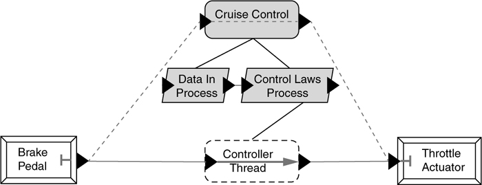
Figure 11-1. End-to-End Flow Instance
11.2. Binding Software to Hardware
An AADL model of an embedded system consists of a software application modeled as threads, processes, data components, connections, and remote subprogram calls, and a computer system modeled as processors, memory, buses, as well as virtual processors and virtual buses. In order to execute the software on the computer hardware you must specify how the software is bound to the hardware. This is often referred to as deployment of the software on hardware. Without such a deployment you cannot perform analysis of operational properties such as performance, fault tolerance, safety criticality, and so on through static analysis and simulation or the generation of a build configuration.
First, we will show you how you use properties to declare such bindings and how you can represent deployment configurations. Then, we will describe to you the different bindings you can specify.
11.2.1. Declaring Bindings with Properties
AADL has a set of predeclared properties that you can use to specify bindings. One set of properties allows you (or a tool) to record the actual binding (e.g., the actual processor binding via the Actual_Processor_Binding property). This property takes as value the reference to the processor that a thread is bound to, and the property is associated with the thread. You do this by declaring the property association in a high-level component that contains both the software thread and the processor hardware, often the top-level system.
Listing 11-6 shows examples of actual binding declarations. The Actual_Processor_Binding declaration refers to Speed_Processor in the Compute_Platform. The property is applied to the Speed_Control_Thread in the Speed_Control_Process, which itself is contained in the application speed_controller (the component type and implementation declarations of the speed control process and thread are not shown).
In this example, we have placed all application software components into the speed_controller system and all computing hardware components in the platform.singlePC system component. The top-level system speed_control_system.complete is then defined to consist of the application software, the computer platform, and the sensor and actuator. Given this top-level system implementation declaration, you can then find the system implementation speed_control_system.deployment1 as an extension of speed_control_system_complete. This extension contains only the binding properties for the system, effectively representing a deployment configuration.
Listing 11-6. A Deployment Configuration
system platform
features
marinebus: provides bus access standard.marine_certified;
end platform;
system implementation platform.singlePC
subcomponents
speed_processor: processor pc.marine_certified;
marine_bus: bus standard.marine_certified;
DRAM: memory DRAM.marine_certified;
connections
bus access marine_bus <-> marinebus;
bus access marine_bus <-> speed_processor.marinebus;
bus access marine_bus <-> DRAM.marinebus;
end platform.singlePC;
system implementation speed_control_system.complete
subcomponents
speed_sensor: device sensor.speed;
throttle_actuator: device actuator.throttle;
speed_controller: system control.speed;
compute_platform: system platform.singlePC;
connections
SC01: port speed_sensor.sensor_data ->
speed_controller.sensor_data;
CC01: port speed_controller.command_data ->
throttle_actuator.command_data;
PhConn1: bus access compute_platform.marinebus <->
speed_sensor.marinebus;
PhConn2: bus access compute_platform.marinebus <->
throttle_actuator.marinebus;
properties
Allowed_Processor_Binding =>
(reference (compute_platform.speed_processor));
Allowed_Memory_Binding_Class => (classifier(DRAM));
end speed_control_system.complete;
-- possibly placed in a separate package
system implementation speed_control_system.deployment1
extends speed_control_system.complete
properties
Actual_Processor_Binding => (reference (speed_processor))
applies to
speed_controller.speed_control_process.speed_control_thread;
Actual_Connection_Binding => (reference (marine_bus))
applies to SC01;
Actual_Memory_Binding => (reference (DRAM)) applies to
speed_controller.speed_control_process;
end speed_control_system.deployment1;
In addition to the actual bindings, you can specify constraints on the bindings. For example, you can restrict the memory binding to memory of a certain type. This is shown in Listing 11-6 for the Allowed_Memory_Binding_class property. Similarly, you can indicate that the binding is constrained to a specific set of platform component (e.g., to specific processors by using the Allowed_Processor_Binding property). These constraint properties are inherited (i.e., they apply to all components in the speed_control_system.complete) for which the properties are declared. You can also specify that two application software components or connections must be co-located or must not be co-located. You use this capability to ensure that duplicate software components are placed on redundant hardware components in fault tolerant system configurations.
11.2.2. Processor Bindings
The processor binding property Actual_Processor_Binding specifies which processor is responsible for executing a particular application thread. You can specify that a thread is bound to one processor or a list of processors, or to a system that contains processors. Using the processor list or system you can for example model that a thread can be executed on either core of a dual-core processor. You can apply the property to a single thread, to a list of threads, or to the enclosing thread group or process. For thread groups and processes, this means that all contained threads are bound to the specified processor(s). You can also use the processor binding properties to specify binding of threads to a virtual processor, and the binding of virtual processors to other virtual processors and to processors. In other words, you can use the virtual processor to represent virtual machines or hierarchies of schedulers. By binding an application thread to a specific virtual processor, you are choosing a particular scheduler. This scheduler itself is then bound to an actual processor. For example, you can have a processor with a rate-monotonic scheduler and a virtual processor that represents a sporadic server for event-driven threads. The sporadic server virtual processor is bound to the rate-monotonic processor to indicate that it takes one task slot, competing with periodic threads. Similarly, you can use virtual processors to represent rate group optimization. Rate group optimization means that a collection of application threads with the same period are executed by a single operating system task that calls the source code of each application thread in sequence. Each of these operating system tasks is a virtual processor that schedules the execution of application threads—all executing at the same rate on the same processor.
11.2.3. Memory Bindings
The memory binding property Actual_Memory_Binding specifies where the source code and the data are stored. You can specify such a binding for a system, process, thread group, and thread. You can also specify the binding for individual data components (e.g., global state variables within a process may be bound separately from the code of the process). You can also specify a separate binding for individual pieces of code (e.g., by binding subprograms and subprogram groups). Finally, you can specify memory bindings for ports (i.e., their location may be different from that of other data or code). As with processor bindings, memory bindings are inherited. For example, they can be declared for a process and they apply to all components inside the process unless those components have their own memory binding. The binding value can be a list of memory components or in the case of memory binding constraints, a list of memory classifiers.
11.2.4. Connection Bindings
The connection binding property Actual_Connection_Binding, specifies a routing of connections through hardware components. These can be port connections as well as data access or subprogram access connections. For example, if two application threads communicate via a port connection and they are bound to two different processors, the connection must be routed through a bus that physically connects the processors. In many cases, the connection routing can be inferred from the processor binding of threads. However, in some cases multiple physical paths may exist (e.g., two processors may be physically connected via dual-redundant buses). In such a case, it may be necessary to identify the particular bus over which the connection should be routed.
Connection binding can involve combinations of buses, processor, memory, devices, as well as virtual buses. You can use the virtual bus to indicate protocols to be involved in the connection. You can also indicate the need for a particular protocol and the fact that a protocol is provided by a processor or a bus through the Provided_Virtual_Bus_Class and Requried_Virtual_Bus_Class properties. Finally, you can indicate the need for a protocol by specifying a required quality of service level such as guaranteed delivery, ordered delivery, or secure delivery by using the Required_Connection_Quality_Of_Service and Provided_Connection_Quality_Of_Service properties. They can be used as constraints for a tool that determines actual bindings, or they can be used by a consistency checker to validate manually entered actual connection bindings.
11.2.5. Binding Remote Subprogram Calls
In Section 10.7, we introduced two ways of modeling remote subprogram calls. One of these ways is through subprogram access features and subprogram access connections (see Section 10.7.3). In that case, you can make use of the connection binding properties to specify a routing of the remote call in terms of the computer hardware. The second way of specifying a remote subprogram call is by identifying the thread that services the call through a call binding property (see Section 10.7.2). In this case, there is no connection through which you can specify the call routing in terms of the computer hardware. Instead, you have additional properties that allow you to specify this binding of the call, namely, Actual_Subprogram_Call_Binding and Allowed_Subprogram_Call_Binding. The use of the Actual_Subprogam_Call_Binding property is illustrated in Listing 11-7. It specifies a path from the processor proc1, which executes the caller code, via the bus vme to the processor proc2, which executes the thread with the remote subprogram.
Listing 11-7. Subprogram Call Binding
system implementation client_server_sys.impl
subcomponents
client_process: process client_process.impl;
server_process: process server_process.impl;
VME: bus VME;
RAM1: memory RAM;
RAM2: memory RAM;
Proc1: processor Intel;
Proc2: processor Intel;
connections
c1: bus access VME -> Proc1.Bus01;
c2: bus access VME -> Proc2.Bus01;
properties
Actual_Subprogram_Call =>
reference(server_process.server_thread.service)
applies to client_process.calling_thread.call_server;
Actual_Subprogram_Call_Binding =>
(reference(Proc1), reference(vme), reference(Proc2))
applies to client_process.calling_thread.call_server;
--
Actual_Memory_Binding => (reference (RAM1))
applies to client_process;
Actual_Memory_Binding => (reference (RAM1))
applies to server_process;
Actual_Processor_Binding => (reference (Proc1))
applies to server_process.server_thread;
Actual_Processor_Binding => (reference (Proc2))
applies to client_process.calling_thread;
end client_server_sys.impl;
--
thread implementation calling.impl
calls {
call_server: subprogram service_it ;
};
end calling.impl;
--
thread server_thread
features
service: provides subprogram access service_it;
end server_thread;
--
thread implementation server_thread.impl
end server_thread.impl;
--
subprogram service_it
end service_it;
--