
Chapter 10. Component Interactions
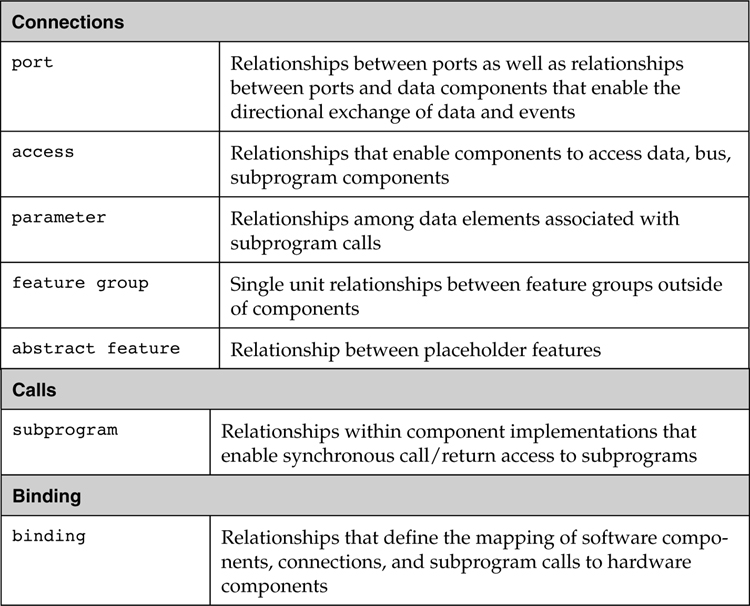
You define component interactions by establishing relationships between the components using connections, calls, and bindings, as summarized in Table 10-1. You use connections to define interactions of components through externally visible features. There are five sets of features: ports, access (data, subprograms, and buses), parameters, feature groups, and abstract features. You use calls to identify the subprogram being called by the calling components (threads and subprograms). You use binding property associations to declare mappings of software to hardware elements and mappings of calls to remote procedures.
Table 10-1. Component Interactions
10.1. Ports and Connections
A port is an interface for the directional transfer of data, events, or both (data and events) into or out of a component. Port connections are pathways for such directional transfers between components
10.1.1. Declaring Ports
Ports are named features in component type declarations. The template for a port declaration is shown in the following box.
name : <direction> <port type> [data identifier] [{properties}];
The direction of the information flow through the port is defined using port direction reserved words: in, out, or in out. The direction in represents a component’s input, while out represents a component’s output. An in out direction indicates that a port is used for both input and output. Incoming and outgoing connections can be made to the same component or different components.
The nature of a port, whether it involves queued data transfer, queued event transfer, or non-queued data transfer, is defined by the port type reserved words: event data port, event port, or data port. The optional data identifier that can be included for data and event data ports defines the nature of the data that can pass through the port. This may be the name of a data type or a data implementation. The optional property associations describe characteristics of the port such as the variable name associated with the port.
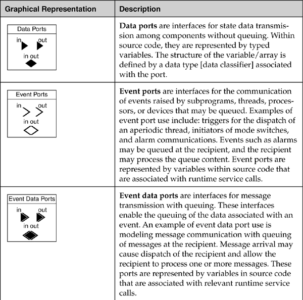
Event data ports are ports for asynchronously sending and receiving data such that the data may be queued if the receiving component is busy. They represent message ports. Event ports are event data ports without data content. They represent discrete events such as a change in switch position or a processor clock interrupt. Data ports are event data ports that retain only the most recent arrival. They represent sampling ports (i.e., ports without a queue) for communicating state information, such as signal streams that are sampled and processed periodically.
Listing 10-1 includes five example port declarations for a process. The data type and the name of the source variable for the port are included in the declaration for the in data port speed. Notice that the source variable name need not be identical to the port name or data type in the AADL model. All of the optional elements of the port declaration are omitted in the declaration of the out event data port Error_Signal.
Listing 10-1. Example Port Declarations
process control
features
speed: in data port raw_speed {Source_Name => "RawSpeed";};
disable: in event port {Required_Connection => false;};
set_speed: in event data port raw_speed.setpt;
throttle_cmd: out data port command_data;
Error_Signal: out event data port;
end control;
The graphical representations and their corresponding declarations for data ports, event ports, and event data ports are summarized in Table 10-2.
Table 10-2. Ports as Interfaces

In addition to user-defined ports, there are three predeclared ports for threads: Dispatch, Complete, and Error. While these are available for use directly in connections to and from the thread, it is not necessary to declare them explicitly. Dispatch is an in event port that can be used to initiate the execution of the thread. Complete is an out event port that signals the completion of a thread. Error is an out event data port that can be used to report thread execution errors.
10.1.2. Declaring Port to Port Connections
The template for a textual declaration of a port to port connection is shown in the following box.
name : port <source port> <connection symbol> <destination port>
[{properties}] [in modes and transitions];
In a port connection declaration, we give the connection a name and refer to the source port and the destination port. A connection can be directional ( → ) or bi-directional ( ↔ ). For directional connections, the source is on the left of the connection symbol and the destination is on the right. In a bi-directional connection, the information can flow in both directions or is determined by the directions of the ports on either end of the connection. If the ports are in out ports, the bi-directional connection indicates the transfer of data in both directions.
The properties for connections include properties for identifying protocols associated with the connection, the quality of service expected from such a protocol, the binding of the connection onto networks (AADL bus) or processors, and connection patterns between component arrays. You can find these properties in the Deployment_Properties property set.
The optional “in modes and transitions” entry associates a connection with specific modes or mode transitions. In other words, a connection may be active in one mode and not in another. Similarly, a connection may only be active during a mode transition (e.g., to exchange state information from a thread that becomes inactive to a thread that becomes active).
10.1.3. Using Port to Port Connections
You declare port to port connections between ports of subcomponents within a component implementation. By doing so you indicate that two subcomponents or subcomponents contained inside each of them communicate data and events.
You also declare port to port connections between a port of a subcomponent and a port of the enclosing component. In this case, you indicate that the output of a subcomponent port is passed to an external component via the port of the enclosing component, and that the input to a subcomponent port comes from an external source via the port of the enclosing component. In other words, port to port connections between two threads in different processes must be declared by following the component hierarchy. For example, two threads in different processes can only communicate with each other if their enclosing processes provide ports for that purpose and the ports are appropriately connected. Following the component hierarchy when declaring port to port connections results in a modular system design. It does not create runtime overhead as in the actual system instance as data is sent directly from one thread to another.
Listing 10-2 has an example textual specification and corresponding graphical representation that includes port and port connection declarations. Within component type specifications, appropriate ports declarations are grouped together in the features section. Supporting data type definitions are included at the end of the table. We could have placed these data type declarations in a separate package.
In Listing 10-2, the connection c_data_transfer is a delayed connection1 between the out data port c_data_out of the thread input (written as input.c_data_out) and the in data port c_data_in of the thread control_plus_output (written as control_plus_output.c_data_in). The connections declaration brake_in: port brake -> input.brake_event; connects the in event port brake of process implementation control.speed_control to the in event port brake_event of the thread subcomponent input. The optional name for the port connection between control_plus_output.c_cmd_out and throttle_cmd is not included in this example. The predeclared event data port Error is used as the source in the connection error_connection. This event data port is not declared as a feature of the originating thread, since it is a standard feature of all threads. Note that the c_data_transfer connection is between two subcomponents, while the other connections declare a mapping between a subcomponent port and a port of the enclosing component.
Graphically, port connections are solid lines between the ports involved in the connection. These can include adornments that define the timing of the connection. For example, double vertical bars adorn a delayed connection (a data transfer that is phase delayed) between data ports for data transfer between periodic threads. A delayed connection is shown in the graphic of Listing 10-2 for the data port connection between the threads input and controller. A double arrow indicates an immediate connection (a data transfer that is within the same frame).
Note the connections between ports on a subcomponent and ports on the boundary of the component in which that subcomponent is contained. The names of the ports involved in these connections can be different. However, these ports must be of the same port type and direction. In addition, for event data and data ports, they must be defined as transferring the same data (e.g., in Listing 10-2 the in data port speed of the control process has the same data declaration raw_speed as the in data port to which is connected the speed_in_data of the thread type control_in). This means that their data types must match. By default, the data types must be identical, but other matching rules, such as equivalence and subset, can be specified. You can use equivalence to indicate that two data types that have been defined independently represent the same data. You can use subset to indicate that the recipient data type represents a subset of the record fields of the sender. Note that a port may be the source of multiple connections, as shown for the connections brake_in1 and brake_in2 within the process implementation control.speed_control that originate at the event port brake.
Communication between data ports on the same processor or processors with shared memory can be mapped into static data variables in the source code unless double buffering is required. Double buffering may be required because the sending and receiving threads execute concurrently or they execute with different periods.
Listing 10-2. Sample Declarations of Data, Event, and Event Data Ports
process control
features
speed: in data port raw_speed;
brake: in event port;
set_speed: in event data port raw_set_speed;
throttle_cmd: out data port command_data;
Error_Signal: out event data port;
end control;
thread control_in
features
speed_in_data: in data port raw_speed;
brake_event: in event port;
set_speed_edata: in event data port raw_set_speed;
c_data_out: out data port processed_data;
end control_in;
thread control_out
features
brake_event: in event port;
c_data_in: in data port processed_data;
c_cmd_out: out data port command_data;
end control_out;
process implementation control.speed_control
subcomponents
input: thread control_in.input_processing_01;
controller: thread control_out.output_processing_01;
connections
speed_in: port speed -> input.speed_in_data;
brake_in1: port brake -> input.brake_event;
brake_in2: port brake -> controller.brake_event;
set_speed_in: port set_speed -> input.set_speed_edata;
c_data_transfer: port input.c_data_out -> controller.c_data_in
{Timing => Delayed;};
port controller.c_cmd_out -> throttle_cmd;
error_connection: port input.Error -> Error_Signal;
end control.speed_control;
thread implementation control_in.input_processing_01
end control_in.input_processing_01;
thread implementation control_out.output_processing_01
end control_out.output_processing_01;
data raw_speed
end raw_speed;
data raw_set_speed
end raw_set_speed;
data command_data
end command_data;
data processed_data
end processed_data;

You can use a port to port communication between threads (i.e., two active software components that may reside in the same or different processes and execute on the same or different processors). You can also connect a thread port to a device port to model the logical interaction between a physical component and the embedded application or between two devices. Finally, you can model the interaction between an application thread and its runtime system by a port connection to a processor port. For example, you can represent exceptions reported by the runtime system as event ports or event data ports. In a port to port connection declaration you refer to a processor port by “processor . <portname>”, where processor identifies the processor the thread executes on.
10.1.4. Constraints on Port to Port Connections
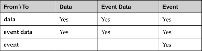
The type of the ports that are connected need not be identical. For example, connections can be made between data ports and event data ports and from event data ports to event ports. The type of the destination port determines how the data or event is transferred and received. An incoming data port can sample the output from a data port or event data port. In this case, it samples a stream of state values or a stream of messages, possibly skipping some sent values or messages or sampling them multiple times. You will use sampling data ports to model sampled processing in control systems, or sampling of message streams to determine whether messages are being sent within a time interval. An event data port can receive and queue output from an event data port and from a data port. In this case, every sent message or state value of the sender is queued to be processed without loss. The output from a data port can be sent to both a data port and an event data port. You may use this to model a control system sampling sensor data and a logging capability recording every sensor reading. An event port can observe and record as a queued event, the arrival of data from a data port, a message from an event data port, or an event from event port. You may use a connection from a data port or event data port to an event port to model a system health monitor that is interested in determining whether the sender is alive. Permitted connections are summarized in Table 10-3.
Table 10-3. Inter-Port Connections
Port to port connections require that the direction of the source port matches the direction of the destination port. For connections between ports of two subcomponents this means that the source port must be an outgoing (out or in out) port, while the destination port must be an incoming (in or in out) port. For connections up the hierarchy from a subcomponent port to a port of the enclosing component, both ports must be outgoing, while for connections down the hierarchy from an enclosing component to a subcomponent both ports must be incoming.
There are restrictions on the topology of port connections. An out data port can be connected to multiple in data ports—a “fan-out” of data to multiple destinations. In this case, each destination port receives an instance of the transmitted data. However, since data ports do not support queuing, an in data port is restricted to a single incoming connection (i.e., cannot have multiple connections from different sources). Since data ports hold a single value, without queuing, outputs from multiple sources would overwrite one another. You should be aware that if you have a system with multiple modes, a thread with an in data port can have a different single incoming connection in each mode.
In contrast, since they support queuing, event and event data ports can have multiple input (fan-in) connections as well as multiple output (fan-out) connections. Multiple inputs at an event or event data port enable the specification of the sequencing as well as the queuing of events.
Data and event data ports include data component classifier references to represent the data type of the data communicated through the port. AADL requires that the data type of the source port matches the data type of the destination port. For example, the connection from the out data port of the thread read to the in data port of the thread scale in Listing 10-2 includes the same data type declaration for each of the ports. By default, the data types have to be identical. However, you can specify other matching rules with the Classifier_Matching_Rule property, such as the destination accepting a subset of the source data, or the protocol to be used in the connection supports conversion between the two data types. The reference to a data component classifier is optional to support creating partial specifications2. Therefore, it is acceptable for one end of a connection not to have a data type declared while the other end does. Similarly, one end of a connection can have just a data component type, while the other end has a data implementation with the same type.
Typically, you want to perform additional consistency checks on port connections that involve data exchange. For example, you may want to ensure that the base type used by the sender to represent the application data type matches that of the receiver (e.g., that both use 16-bit signed integer to represent temperature). Similarly, you may want to check that both application data types use the same measurement unit (e.g., Celsius). The AADL Data Modeling Annex standard defines a set of properties to record such information.
A port with in out direction represents a single interface into and out of a component, in effect both an in port and an out port. You can declare a single bidirectional port to port connection between two in out ports. In this case, the two components communicate in both directions. You can also declare multiple directional connections to an in out port as shown in Listing 10-3, where the in out port error_data on the process monitor receives data from the out data port error_data of the process input and outputs a value to the in data port error_response of process input. The out data port error_data of process input is connected to two receiving ports, one on the process master and the other on the process monitor via an immediate connection. The connection from the in out data port error_data on the process monitor to the error_response in data port on the process input is a delayed connection3. The graphic in the lower portion shows the topology for these connections.
As with unidirectional data ports, an in out data port can be mapped to a single static data variable within application source code. Since an in out port maps to a single static variable, an existing incoming value of a port will be overwritten by the source code when an output value is written to that port.
Listing 10-3. Connections with in out Ports
system basic
end basic;
system implementation basic.monitor
subcomponents
input: process input;
monitor: process monitor;
master: process master;
connections
C1: port input.error_data -> master.error_data
{Timing => Immediate;};
C2: port input.error_data -> monitor.error_data
{Timing => Immediate;};
C3: port monitor.error_data -> input.error_response
{Timing => Delayed;};
end basic.monitor;
process input
features
error_response: in data port;
error_data: out data port;
end input;
process monitor
features
error_data: in out data port;
end monitor;
process master
features
error_data: in data port;
end master;

10.1.5. Port Communication Timing
Port to port connections define communication between active components of a system (e.g., between two threads, a thread and a device, or two devices). The port type and the dispatch protocol of the thread or device determine the timing of the communication. Periodic dispatch protocols allow for sampling of input, while in other cases the arrival of events or data can trigger the dispatch as discussed in Section 6.1. In the case of port communication between two periodic threads/devices through data ports, AADL supports sampled processing with up- and down-sampling as well as deterministic sampling. The latter ensures that latency jitter is minimized—an important factor for control systems whose stability is sensitive to such jitter.
For outgoing event and event data ports the transfer occurs at the time it is initiated by the sender through a Send_Output service call in the source code. This time can be specified through the Output_Time property on the outgoing port. Once the sent output is received by a destination event or event data port, it is placed in its input queue. The arrival of the message may trigger a dispatch of the recipient thread, if it is listed as a dispatch trigger port for the thread. By default, the one message in the input queue is “frozen” at thread dispatch (i.e., it is removed from the queue and made available to the source code in a port variable). The content of this port variable is guaranteed not to change during the execution of the thread, even though new messages may arrive. This means any messages or events arriving after the dispatch are queued, but not available to the recipient until the next dispatch. You can indicate through a Dequeue_Protocol property that the whole queue content should be frozen and made available to the thread source code for processing in the current dispatch. For example, this is useful when you have a health monitor that periodically wants to examine alarm events or messages. You can also indicate that the input should be “frozen” during the execution of the thread by using the Input_time property on the incoming port. In the source code, it is expressed by an explicit Receive_Input service call. The number of queued items that have been frozen can be retrieved by a Get_Count service call. If the queue is empty at the time of a freeze, the count will be zero.
In the case of an event port connection, the source may be an internal event. This is declared by using self.eventname as the source. The identifier eventname is a specific source internal to the component containing the connection. For example, in the case of a thread the internal event may originate as an exception from the source code of the thread or from the execution platform on which the thread is executing. If the containing source is a process or thread group, the internal event can represent an event related to a fault of this component; the fault condition may be modeled with the Error Model Annex [EAnnex].
For outgoing data ports the data transfer is by default initiated at completion time. You can indicate a send during the execution through the Output_Time property. In that case, the transfer is initiated by an explicit Send_Output call in the source code.
For incoming data ports the content is “frozen” the same way as for event data ports. In other words, by default it is frozen at dispatch time, or otherwise at a time specified by the Input_Time property. Only the most recent value is available to the source code. If no new data has been received since the last dispatch, the old value is still available, but marked as not fresh. The source code can determine the freshness through an Updated service call.
10.1.6. Sampled Processing of Data Streams
In this scenario, the sender and receiver can be threads or devices. For port connections with a periodic recipient with a data port, the connection represents sampling communication. This means that the receiver samples a data stream at a given rate. The receiver samples independent of the rate at which the sender executes and sends data. If the sampling rate differs from the rate at which the data is sent, over- or undersampling may occur. You can typically find independent sampling in systems with processors and devices interconnected by buses or networks and operating on independent clocks.
In a sampling data port connection the receiver reads the output of a source at the receiver’s dispatch time. This data transfer occurs independently from the execution characteristics of the sending thread or device. An offset time can be defined by assigning a value to the Input_Time property for the receiving data port. This property specifies the amount of execution time after dispatch before the input is read.
The rate at which data arrives may be the same, higher, or lower than the sampling rate and it may be constant (sent by a periodic sender) or variable (sent by a sender whose execution is triggered by random events). As a result, the receiver may sample the same input multiple times (over-sampling) or the receiver may not sample all elements of the data stream (undersampling). In the case of a variable data stream, a sampling thread will turn such a data stream into an output data stream with a periodic rate.
Since sampling communication is independent of the execution of the source component, the data stream is sampled non-deterministically. Consider two threads that are executing concurrently on different processors. While each thread will execute periodically at 20Hz, the relative start times for execution of the threads can vary. These variations will result in non-deterministic sampling, as illustrated in Figure 10-1. In this example, within the first 50ms (20Hz) frame of the sequence, thread control receives the output of the initial dispatch of read_data (the value output in the same frame). However, in the second 50ms (20Hz) frame the thread control again receives the output of the initial dispatch of read_data (the result from the previous frame). This results because the second execution of read_data is not complete and its output is not available when the thread control executes. The third dispatch of control may receive the output from the third dispatch of read_data, as shown. Unlike the deterministic semantics of immediate and delayed connections, the semantics of a sampling connection does not constrain the order of execution of communicating threads or devices and non-determinism may occur in the communication.
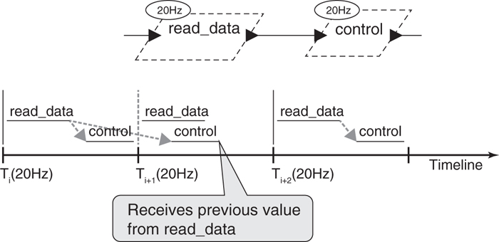
Figure 10-1. Non-Determinism in Sampling Connections
10.1.7. Deterministic Sampling
If both the sender and the receiver thread are periodic, you can specify that their data transfer is coordinated, such that deterministic sampling occurs. You can indicate that the transfer should be immediate, having the effect of guaranteed mid-frame communication, or as delayed, indicating phase-delayed communication, using the Timing property on the connection. Deterministic sampling limits the amount of jitter in data latency. Jitter can affect the stability of control systems. You can find phase-delayed communication in systems that synchronize around a periodic bus, such as a CAN bus or a MIL-STD 1553 bus. Mid-frame communication is typically used within a processor, but can be supported across tightly coupled processors by coordinating the completion and dispatch of the sender and the receiver.
For immediate data port connections between periodic threads, data transmission is initiated when the source thread completes and enters the suspended state. The value delivered to the in data port of a receiving thread is the value produced by the sending thread at its completion. For an immediate connection to occur, the threads must share a common (simultaneous) dispatch. However, the receiving thread’s execution is postponed until the sending thread has completed its execution. This aspect can be seen in Figure 10-2, where the immediate connection specifies that the thread control must execute after the thread read_data, within every 50ms period. In addition, the value received by the thread control is the value output by the most recent execution of the thread read_data. The ovals in Figure 10-2 labeled with (20Hz) are representations of the thread’s execution rate and establish a period of 50ms for the thread that it adorns.

Figure 10-2. An Immediate Connection
For the graphical timelines in Figure 10-2 and Figure 10-3, a horizontal bar above the timeline that is labeled with a thread name represents the execution time of that thread. The left edge represents the start and the right edge represents the termination of the thread’s execution. A solid or segmented arrow between thread execution bars represents a data transfer between threads. A segmented arrow represents a delayed (e.g., Figure 10-3) or a repeat transfer (e.g., Figure 10-4).

Figure 10-3. A Delayed Connection
For a delayed data port connection between periodic threads, the value from the sending thread is made available at its deadline to the receiving thread at its next dispatch that is the same or follows the deadline4. For delayed port connections, the communicating threads do not need to share a common dispatch. In this case, the data available to a receiving thread is that value produced at the most recent deadline of the sending thread. If the deadline of the sending thread and the dispatch of the receiving thread occur simultaneously, the transmission occurs at that instant. The impact of a delayed connection can be seen in Figure 10-3, where the thread control receives the value produced by the thread read_data in the previous 50ms frame. As shown in Figure 10-3, a delayed connection is symbolized graphically by double cross hatching adorning the connection arrow between the ports.
Deterministic oversampling is shown in Figures 10-4 and 10-5. In the case of a delayed connection in Figure 10-4, the value from read_data is available at its deadline. It is received by the two executions of control whose dispatch coincides with or follows that deadline (e.g., read_data may have a pre-period deadline). Thus, the two executions of control occurring within an execution frame of read_data receive the value produced in the preceding frame of read_data.

Figure 10-4. Oversampling with Delayed Connections

Figure 10-5. Oversampling with Immediate Connections
In contrast, consider the case of immediate connections as shown in Figure 10-5, the values available for two sequential executions of control are the same, the value produced within the 10Hz execution frame of read_data. This result is accomplished by delaying the execution of the first control within the frame until the completion of read_data. Notice that this can only occur if both read_data and an execution of control can successfully complete to meet the deadline within the execution frame of control.
Deterministic undersampling is shown in Figure 10-6. For a delayed connection the data provided to an execution of control is the value produced by read_data that is available at the simultaneous dispatch of the threads. That value is produced at the most recent read_data deadline, which may coincide with the control thread’s dispatch. In the case of an immediate connection, as shown in Figure 10-7, the value provided to the thread control is the value produced by read_data at the end of its first execution after the simultaneous dispatch, and the execution of control is delayed until read_data has completed.

Figure 10-6. Undersampling with Delayed Connections
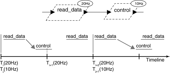
Figure 10-7. Undersampling with Immediate Connections
10.1.8. Mixed Port-Based and Shared Data Communication
Sometimes it is necessary for you to combine a subsystem using port-based communication with a subsystem that uses shared data communication. AADL supports this by allowing you to declare connections between ports and data components (or data access features representing access to data components). For example, you can declare a connection from a data component to a data port on a thread. In this case, the content of the data component is read at the time of dispatch of the thread and made available to the application source code in the port variable. This is different from you modeling the thread with a requires data access feature, where the thread can read or write the data component any time during its execution.
You can declare a port connection from a data port or an event data port to a data subcomponent or a data access feature. In this case, a send operation on the port results in writing the sent data value into the data component. You can also declare a port connection from a data component to a data port or event data port. In this case, whenever the data component is written the data is also transferred to the port. Notice that runtime system implementations may not support monitoring of writes to data components to initiate the send to a port.
Listing 10-4 shows example connections between ports and data components. There are data ports connected to the data component store_p. The content of store_p is updated by the thread data_mgt through the connection to_store_p. Content from store_p is received by the thread l_control via the sampling connection from_store_p. Directional control information from the thread l_control is stored in the data component store_d via the connection to_store_d from the event data port output to the data component store_d. The other connections (data_in and cmd_out) where sensor data is received by and commands are output from the process are also shown. There must be consistency in the data references for connection of ports and data components. For example, the output data port on the thread data_mgt and the input port on the thread l_control both refer to the data implementation store.processed and the data component store_p is an instance of that implementation. Note that the Access_Right property for both data components is read_write.
Listing 10-4. Port to Data Component Connections
process control
features
sensor_data: in data port ;
cmd: out data port ;
end control;
process implementation control.directional
subcomponents
data_mgt: thread manage.basic;
l_control: thread controller.basic;
store_p: data store.processed {Access_Right => read_write;};
store_d: data store.direction {Access_Right => read_write;};
connections
to_store_p: port data_mgt.output -> store_p;
from_store_p: port store_p -> l_control.input;
to_store_d: port l_control.output -> store_d;
data_in: port sensor_data -> data_mgt.input;
cmd_out: port l_control.cmd_out -> cmd;
end control.directional;
--
thread manage
features
input: in data port;
output: out data port store.processed;
end manage;
thread implementation manage.basic
end manage.basic;
thread controller
features
input: in data port store.processed;
output: out event data port store.direction;
cmd_out: out data port;
end controller;
thread implementation controller.basic
end controller.basic;
data store
end store;
data implementation store.direction
end store.direction;
data implementation store.processed
end store.processed;

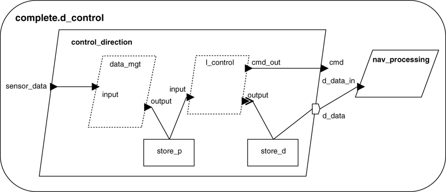
Listing 10-5 extends the example in Listing 10-4 by adding a system that consists of a nav_processing and an instance of the process control.directional named control_direction. The textual specification is a partial listing, including only added or modified portions of the textual specifications from Listing 10-4 and portions of the specification of the system complete.d_control. In this example, a provides data access feature d_data is added to the process type control. It provides access to the data subcomponent store_d. A connection is made from the component store_d to the access feature d_data and from d_data to the data port d_data_in on the component nav_processing.
Listing 10-5. Port-Data Component Connections
system implementation complete.d_control
subcomponents
control_direction: process control.directional;
nav_processing: process nav;
connections
dc: port control_direction -> nav_processing.d_data_in;
end complete.d_control;
process nav
features
d_data_in: in data port store.direction;
end nav;
process control
features
sensor_data: in data port;
cmd: out data port;
d_data: provides data access store.direction; -- added
end control;
process implementation control.directional
subcomponents
data_mgt: thread manage.basic;
l_control: thread controller.basic;
store_p: data store.processed {Access_Right => read_write;};
store_d: data store.direction {Access_Right => read_write;};
connections
to_store_p: port data_mgt.output -> store_p;
from_store_p: port store_p -> l_control.input;
to_store_d: port l_control.output -> store_d;
data_in: port sensor_data -> data_mgt.input;
cmd_out: port l_control.cmd_out -> cmd;
d_acc: data access store_d -> d_data; -- added
end control.directional;
10.1.9. Port and Port Connection Properties
AADL provides a number of predeclared properties for ports. Some properties deal with the fact that the port has a representation in the application source code. For example, Source_Name is used to specify the name of the port variable in the source code that is associated with a port. Source_Data_Size is inferred from the property on the data component classifier that the data port or event data port references.
Event ports and event data ports can trigger the dispatch of a thread. In that case, you can indicate that the thread executes a different piece of source code for different ports instead of a single entry point for all dispatches by specifying the subprogram to be invoked, execution time, and deadline (if different from that specified for the thread). You can also specify the queue characteristics for event and event data ports, such as size, overflow handling, and dequeuing.
You can use the Required_Connection property to indicate whether the component requires a connection on the port or whether it is optional. This allows you to record in the component specification whether its implementation can adapt to an unconnected port (the connection is optional), or whether the component assumes the connection to always be in place. By default, a connection is assumed to be required. You can invoke a consistency check on an AADL model to ensure that this property is satisfied.
AADL provides a number of predeclared properties for port connections. These properties focus on the deployment of the application software (i.e., the mapping of the connection onto the underlying runtime system). You can specify the expected quality of service for the communication protocol and hardware (virtual bus, bus, and processor), such as guaranteed, secure, and ordered delivery. You can also indicate that the connection requires a particular protocol or must occur over a particular network (bound to a particular bus type or bus instance). In some cases, you may want to specify these properties on a port in order to document any assumptions the component makes about communication through a specific port. Finally, you can indicate whether a connection must or must not be co-located with another connection in order to assure redundant communication.
10.1.10. Aggregate Data Communication
You may have a situation where a subsystem (process) is collecting data from multiple sensors or multiple threads produce output that is to be sent to another subsystem. You may have grouped the output from these ports into a feature group at the process level and connected it to the destination subsystem (process). As we discuss in further detail in Section 10.4 a feature group connection represents a collection of individual connections between the ports in the feature group. The threads and devices on the ends of each of the connections communicate independently.
In some cases, you may want to model a system where a subsystem collects the data produced by its components and sends it as an aggregate to another subsystem. You could introduce an extra thread in the subsystem that receives all the outputs, places them in a data record and sends it on a single data port. AADL offers an alternative way of modeling aggregate data communication without having to introduce the extra thread. You define a data component implementation that contains data subcomponents (acting as record field) for each of the data elements of aggregate data record. You then use this data classifier as data type of a single data port in the enclosing process. Within the process implementation, you then connect the output port of each thread or device to a data record field in the process output port. At the destination subsystem, a single thread may receive the aggregate data record or different threads may receive different fields of the data record. As indicated in Section 10.1.4, you can also specify that different threads or subsystems receive different subsets of the aggregate data, modeling the OMG Data Distribution Service [DDS].
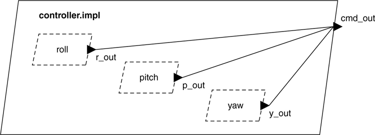
The aggregation of data from multiple sources into a single data record is illustrated in Listing 10-6, where the process controller.impl contains three threads. Each thread has an out data port that is connected to the aggregate data port cmd_out that is a feature of the process controller.impl. The port cmd_out has a data classifier agg_data.impl containing three subcomponents. The connections in the process controller.impl are made from the out data port of each thread to a specific data subcomponent of the port cmd_out. For example, the connection cr is from the port r_out on the subcomponent roll to the data subcomponent cmd_data_r of the implementation agg_data.impl. Note that the data type on the port in the connection must match the data classifiers for the corresponding subcomponent. Access to the data subcomponents of the port cmd_out is declared in the type agg_data.
Listing 10-6. Aggregate Data Port Example
data agg_data
end agg_data;
data implementation agg_data.impl
subcomponents
cmd_data_r: data cmd_data_2;
cmd_data_p: data cmd_data_1;
cmd_data_y: data cmd_data_2;
end agg_data.impl;
data cmd_data_1
end cmd_data_1;
data cmd_data_2
end cmd_data_2;
process controller
features
cmd_out: out data port agg_data.impl;
end controller;
process implementation controller.impl
subcomponents
roll: thread roll;
pitch: thread pitch;
yaw: thread yaw;
connections
cr: port roll.r_out -> cmd_out.cmd_data_r;
cp: port pitch.p_out -> cmd_out.cmd_data_p;
cy: port yaw.y_out -> cmd_out.cmd_data_y;
end controller.impl;
Aggregate data ports are useful if the data from a set of simultaneously dispatched periodic threads must be delivered together. For example in Listing 10-6, the aggregate data port of the enclosing process controller.impl ensures that the data from its threads is delivered at the same time. The actual timing of the transmission is determined by the execution of the threads connected to the aggregate data port such that the sending of data is initiated at the completion of the execution of the threads (at the time the last thread completes its execution).
10.2. Data Access and Connections
In your system, multiple threads may operate on a common data area (i.e., they share access to a data component). Similarly, a subprogram may access an external data component by reference. In AADL, you model this through data access features and access connections. You can specify concurrency control on such shared data components through the Concurrency_Control_Protocol property on the data component itself.
Data access is declared either as requires access feature indicating that a component needs access to a component, or as provides access feature, indicating that a component allows access to a data component declared within it. The template for an access interface declaration is shown in the following box. The access direction is either provides or requires. The optional component identifier is a data classifier reference that specifies the data type of the data component to be accessed.
name : (provides | requires) data access [component identifier]
[{properties}];
You use access connection declarations to specify a path between these data access features and the actual data component to be referenced. Data access connections are similar to port connections with connection name, a source and destination, a directional or bidirectional connection symbol, optional properties, and they can be declared to be active only in certain modes. The template for a data access connection declaration is shown in the following box.
name : data access <source> <connection symbol> <destination>
[{properties}] [in modes];
You can declare the access connection to be bidirectional ( ↔ ) or to be directional ( → ). In the case of a bidirectional access connection read and write access is possible, but may be restricted by the Access_Right property on the data component or the data access feature. In the case of a directional access connection the direction indicates reading from a data component (the data component is the source of the access connection) or writing to the data component (the data component is the destination of the access connection) and must be compatible with the Access_Right property values if they are specified.
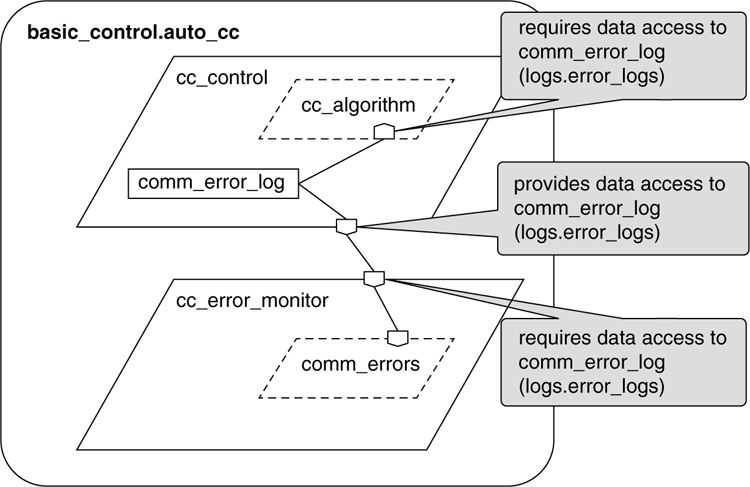
Listing 10-7 presents a system basic_control.auto_cc with two subsystems (processes) that share access to a data component contained in one of them. The thread subcomponent cc_algorithm of the process implementation control.cc_control is shown to require access to an instance of the data implementation logs.error_logs. The RWLogAccess data access connection in the process implementation control.cc_control connects comm_error_log (an instance of logs.error_logs) to the requires access feature error_log_data on the thread cc_algorithm.
Similarly, the thread subcomponent comm_errors requires access to the data subcomponent comm_error_log (logs.error_logs) of the process cc_error_monitor. This connection is a remote connection across address spaces, where the process cc_control provides access to its data subcomponent. There is a data access connection that extends through the component hierarchy from the data instance comm_error_log to the thread comm_errors. In addition, there is a data access connection that extends through the component hierarchy from the data instance comm_error_log to the thread comm_errors, both of which are subcomponents of the process cc_control.
Notice the concurrent access to the data subcomponent comm_error_log (logs.error_logs) in the example. The standard property Concurrency_Control_Protocol is used to coordinate the access, as shown in the subcomponent declaration of the data subcomponent comm_error_log. The property Access_Right is used to define the access protocol of the connection read_only, write_only, or read_write. This property indicates the desired access. For example if the value is read-only, the data component must offer read access and connections to that access feature must be read. If the access is read-write, an access connection to the component providing access can be read, write, or both. The property Access_Time specifies the period of time at which a shared data component is accessed.
Listing 10-7. Shared Access Across a System Hierarchy
system basic_control
end basic_control;
system implementation basic_control.auto_cc
subcomponents
cc_control: process control.cc_control;
cc_error_monitor: process monitor.error_monitor;
connections
a_01: data access cc_control.error_log_data -> cc_error_monitor.error_data_in;
end basic_control.auto_cc;
--
process control
features
error_log_data: provides data access logs.error_logs
{ Access_Right => read_only;};
end control;
process implementation control.cc_control
subcomponents
comm_error_log: data logs.error_logs
{Concurrency_Control_Protocol => Interrupt_Masking;};
cc_algorithm: thread algorithm.cc;
connections
RWLogAccess: data access comm_error_log <->
cc_algorithm.error_log_data;
ROLogAccess: data access comm_error_log -> error_log_data ;
end control.cc_control;
thread algorithm
features
error_log_data: requires data access logs.error_logs
{ Access_Right => read_write;};
end algorithm;
thread implementation algorithm.cc
end algorithm.cc;
data logs
end logs;
data implementation logs.error_logs
end logs.error_logs;
process monitor
features
error_data_in: requires data access logs.error_logs
{ Access_Right => read_only;};
end monitor;
process implementation monitor.error_monitor
subcomponents
comm_errors: thread m_algorithm.errors;
end monitor.error_monitor;
thread m_algorithm
features
c_error_data: requires data access logs.error_logs
{ Access_Right => read_only;};
end m_algorithm;
thread implementation m_algorithm.errors
end m_algorithm.errors;
10.3. Bus Access and Connections
The computer hardware components and physical components of your embedded system are physically connected to each other via buses. You accomplish this by declaring the need for a component such as a processor or sensor device to access a bus of a certain type, and making the access connection through bus access connection declarations. For example, if a processor requires access to a PCI bus, the connection of the processor’s requires bus access feature to the bus establishes a physical connection between them. Similarly, a device such as a digital camera may have a requires bus access feature of bus type usb that is connected to a bus of type usb. Bus access connections can be directional or bidirectional. As in the case of the data access connection, the direction indicates transfer to or transfer from the bus and must be compatible with the Access_Right property values of the source and destination.
The syntax for the bus access features and bus access connections is the same as for data access with the keyword data replaced by bus. Listing 10-8 shows an example of bus access connections for a simplified cruise control system that consists of a cruise control unit (system component) and pilot input, speed sensor, and throttle devices. Additional execution hardware for the system consists of a processor that executes the application software and a bus connecting the hardware components. A complete path for a bus access connection is between a bus and a terminating requires bus access feature (i.e., the bus access feature of the component to be connected to the bus). This may progress through multiple access features both provides and requires. The figure in the lower portion of Listing 10-8 is a graphical representation for required access features and connections to the bus declared in the text. Several devices and a processor are connected to a CANBus within the cruise control system. The CANBus is also made accessible to other components outside the cruise control system. Only the connection declaration from the CANBus to the external_access feature for the system cruise_control_system.impl is included in the example.
Listing 10-8. Basic Bus Access and Access Connection Declarations
system cruise_control_system
features
external_access: provides bus access CANBus.impl;
end cruise_control_system;
system implementation cruise_control_system.impl
subcomponents
pilot_input_unit: device pilot_input_unit;
speed_sensor: device speed_sensor;
CCU: system CCU_system;
throttle_actuator: device throttle_actuator;
M555: processor M555;
CANBus: bus CANBus.impl;
connections
-- bus access connections
bus_access_01: bus access CANBus <-> pilot_input_unit.bus_access;
bus_access_02: bus access CANBus <-> speed_sensor.bus_access;
bus_access_03: bus access CANBus <-> throttle_actuator.bus_access;
bus_access_04: bus access CANBus <-> M555.bus_access;
bus_access_05: bus access CANBus <-> external_access;
end cruise_control_system.impl;
device pilot_input_unit
features
bus_access: requires bus access CANBus.impl;
end pilot_input_unit;
bus CANBus
end CANBus;
bus implementation CANBus.impl
end CANBus.impl;
device speed_sensor
features
bus_access: requires bus access CANBus.impl;
end speed_sensor;
device throttle_actuator
features
bus_access: requires bus access CANBus.impl;
end throttle_actuator;
processor M555
features
bus_access: requires bus access CANBus.impl;
end M555;

Listing 10-9 illustrates how to model two subsystems with hardware components and bus connections, where their local buses are interconnected via a backbone. Some of the specifications are not complete (e.g., type rather than implementation classifiers are used in defining some of the components and subcomponents). In the illustration, each subsystem uses a local 1553 bus to connect its internal devices. The two subsystems are interconnected via an Ethernet backbone. We do this by connecting each of the local buses directly to the backbone via requires bus access features on the local buses. The bus access, requires, provides, and connections are shown both graphically (lower portion of Listing 10-9) and as AADL text declarations.
Listing 10-9. Example Bus Access Connection Declarations
system vehicle_system
end vehicle_system;
system implementation vehicle_system.impl
subcomponents
bow: system frontend.impl;
stern: system backend.impl;
backbone: bus Ethernet;
connections
bus access backbone <-> bow.network_bus;
bus access backbone <-> stern.network_bus;
end vehicle_system.impl;
system frontend
features
network_bus: requires bus access Ethernet;
end frontend;
system implementation frontend.impl
subcomponents
B_1553: bus B_1553;
PC1: processor PC;
Obstacle_Sensor: device IR_Sensor;
connections
C01: bus access B_1553.network_bus <-> network_bus;
C02: bus access B_1553 <-> PC1.LocalBus;
C03: bus access B_1553 <-> Obstacle_Sensor.LocalBus;
end frontend.impl;
system backend
features
network_bus: requires bus access Ethernet;
end backend;
system implementation backend.impl
subcomponents
PC2: processor PC;
B_1553: bus B_1553;
Depth_Sensor: device UltraSound_Sensor;
connections
C01: bus access B_1553.network_bus <-> network_bus;
C02: bus access B_1553 <-> PC2.LocalBus;
C03: bus access B_1553 <-> Depth_Sensor.LocalBus;
end backend.impl;
processor PC
features
LocalBus: requires bus access B_1553;
end PC;
bus B_1553
features
network_bus: requires bus access Ethernet;
end b_1553;
device IR_Sensor
features
LocalBus: requires bus access B_1553;
end IR_Sensor;
device UltraSound_Sensor
features
LocalBus: requires bus access B_1553;
end UltraSound_Sensor;
bus Ethernet
end Ethernet;

10.4. Feature Groups and Connections
Feature groups represent collections of component features or other feature groups. You can specify the makeup of a feature group by a feature group type. You can connect feature groups using a single connection declaration. From within a component, features contained within a feature group can be connected to individually. From outside a component, feature groups can be connected as a single unit, where this single connection represents multiple feature connections. Feature groups allow the number of connection declarations to be reduced, especially at higher levels of a system, when multiple features from one subcomponent and its contained subcomponents must be connected to features in another subcomponent and its contained subcomponents. You can group features with common properties (e.g., all event ports, all bus accesses) or mix feature types and directions within a feature group. When a feature group is declared for a component, it may be only partially specified by leaving off the feature group type, or by referring to a feature group type for which the features have not been filled in yet. This is useful when you want to model interaction between subsystems early in the development without knowing the exact details of the interactions.
10.4.1. Declaring Feature Group Types
The content of a feature group is defined in a feature group type declaration that explicitly identifies the individual features and feature groups that comprise it. There is no implementation declaration for a feature group. Feature group types can be declared for any kind of feature and may consist of one type of feature (e.g., ports) or a composite of a variety of feature types. Feature group type declarations are placed in packages separate from or together with component type and implementation declarations.
The declaration is similar to a component type declaration with a features and a properties section. As with other component type declarations, properties of the feature group can be declared and a feature group type can be extended and refined.
Three examples of feature group type declarations are shown in Listing 10-10. The feature group roll_set includes a mix of features including data and event ports, a bus access, and the feature group error_set. The feature group error_set includes a requires access declaration for the data component error_data. Two input ports are included as the features for the feature group dual_Inports.
Listing 10-10. Example Feature Group Type Declarations
feature group roll_set
features
roll_data: in data port;
roll_cmd: out data port;
engage: in event port;
h_bus: requires bus access;
errors: feature group error_set;
end roll_set;
feature group error_set
features
sensor_error: in data port;
range_error: out event data port;
error_log: requires data access error_data;
end error_set;
feature group dual_Inports
features
input1: in data port;
input2: in data port;
end dual_Inports;
A feature group type can be declared as the inverse of another feature group type. This is useful for matching the type of the source and destination of feature group connections, as we will see in Section 10.4.3. This relationship is indicated by the reserved words inverse of and the name of a feature group type. You may declare a feature group type as inverse without explicitly listing the features. In this case, the features are known by the names declared in the opposite feature group type. The features of the inverted feature group must be in the same order as in the referenced feature group but with the opposite directions. A feature group type that is named in an inverse of statement cannot itself contain an inverse of statement. Thus, a chaining of inverses, such as B inverse of A and C inverse of B, is not permitted.
Feature group type declarations using inverse of are shown in Listing 10-11. The feature group control_plug is simply the inverse of the feature group control_socket. The feature group type control_plug_independent has declared the features with different names; they are matched in order with the features of the inverse feature group type control_socket.
Listing 10-11. A Feature Group Type Declaration and Its Inverse
feature group control_socket
features
Wakeup: in event port;
Observation: out data port position;
end control_socket;
feature group control_plug
inverse of control_socket
end control_plug;
feature group control_plug_independent
features
Activate: out event port;
Measurement: in data port position;
inverse of control_socket
end control_plug_independent;
Figure 10-8 contains graphical icons for feature groups and their connections. Feature groups can bundle different features and port types and directions as shown.

Figure 10-8. Graphical Representations of Feature Groups
10.4.2. Declaring a Feature Group as a Feature of a Component
To declare a feature group as a feature of a component type, you use the declaration template shown in the following box.
name : feature group [ [ inverse of ] feature group type]
[{properties}] ;
The optional feature group type reference defines the contents of the feature group for the component. Initially, this reference may be omitted in the declarative model. The feature group may refer to a feature group type that initially does not have any features. This allows you to model interactions between two subsystems without knowing the details of the interaction through a collection of ports and other features. You can declare the feature group to be the inverse of a feature group type. This indicates that it represents the features in the feature group type, but with opposite direction. This is useful when matching the feature group types of feature group connections (see Section 10.4.3). By using inverse of in the feature declaration you can avoid having to declare two feature group types, one for each end of a port group connection.
Examples of feature group declarations are shown in Listing 10-12. These examples reference the feature group types shown in Listing 10-10 and are excerpts from a complete specification consisting of the relevant declarations and portions of declarations needed to show what is required in specifying a specific feature group. Note that feature group declarations can be mixed with other feature declarations as shown for the thread read_data.
Listing 10-12. Sample Feature Group Declarations
system control
features
roll_01: feature group roll_set;
end control;
thread read_data
features
inputs: feature group inverse of dual_Inports;
output: out data port;
end read_data;
thread monitor
features
error_set: feature group error_set;
end monitor;
10.4.3. Declaring Feature Group Connections
Connections can be made between feature groups of two subcomponents, or between the individual features within a feature group of an enclosing component and features of subcomponents. The declaration template for a feature group connection is shown in the following box.
name : feature group <source feature group> <->
<destination feature group> [{properties}] [in modes];
Elements of a feature group of a component can be individually connected to features of subcomponents within that component. However, elements of a feature group of a subcomponent cannot be referenced outside the subcomponent (i.e., they cannot be connected to feature group elements or ports of other subcomponents). In other words, grouping and pulling apart elements of a feature group can occur when going up or down the component hierarchy, but not within the same level of the component hierarchy. This is shown topologically in Figure 10-9, where the feature group gc_data has individual connections to ports on the subcomponents of the process GandC. In addition there is a single connection from the feature group c_data to the feature group c_data_inv between two threads of the process GandC.
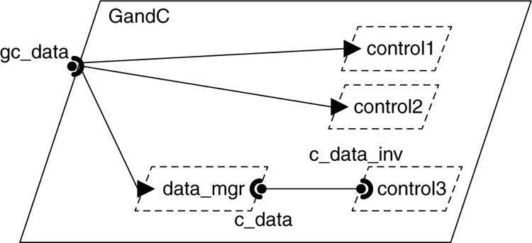
Figure 10-9. Individual Feature Group Connections
Excerpts from an AADL model for a simple cruise control system are shown in Listing 10-13. They include a sample feature group connection for the feature group mode_control_group and its inverse. The feature group mode_control_group combines all of the event ports emanating from a data processing component that impact the modal behavior of a control system. The single feature group connection d_to_c is shown within the system implementation subsystem.cc_process_subsystem between the process process_raw_data and the process controller. The individual connections from each of the event ports in the feature group mc_in (an instance of the inverse of the feature group mode_control_group) to in event ports on the three subcomponent threads of the process controller. A graphical representation of these connections is shown in the lower portion of Listing 10-13. Individual ports and connections are not labeled in the graphic.
Listing 10-13. Sample Feature Group Connection Declarations
system subsystem
end subsystem;
system implementation subsystem.cc_process_subsystem
subcomponents
process_raw_data: process process_data.cc_process_raw_data;
controller: process control.cc_control;
connections
d_to_c: feature group process_raw_data.mc_out <->
controller.mc_in;
end subsystem.cc_process_subsystem;
process process_data
features
mc_out: feature group mode_control_group;
end process_data;
process control
features
mc_in: feature group mode_control_group_inverse;
end control;
thread controller
features
mode_event: in event port;
end controller;
process implementation control.cc_control
subcomponents
control1: thread controller;
control2: thread controller;
control3: thread controller;
connections
C1: port mc_in.cc_on_out01 -> control1.mode_event;
C2: port mc_in.cc_off_out01 -> control2.mode_event;
C3: port mc_in.brake_on_out01 -> control3.mode_event;
end control.cc_control;
process implementation process_data.cc_process_raw_data
end process_data.cc_process_raw_data;
feature group mode_control_group
features
cc_on_out01: out event port;
cc_off_out01: out event port;
brake_on_out01: out event port;
end mode_control_group;
feature group mode_control_group_inverse
inverse of mode_control_group
end mode_control_group_inverse;

The feature group types of connected feature groups must match. By default, this means that the feature group types must be identical for connections from a subcomponent to the enclosing component, and they must be inverses of each other on connections between subcomponents (i.e., they must have the same set of features but with opposite direction).
It is possible to have two other matching rules: equivalence/complement and subset. Equivalence/complement is used when feature group types have been defined independently by different teams and cannot be modified by the integrator to add an inverse of indicator. Subset is used to allow a destination feature group to be a subset of the source feature group, as is the case when modeling the OMG Data Distribution Service [DDS].
The connection matches are specified by the Classifier_Matching_Rule property. The standard values of this property for feature group connections up or down the component hierarchy and for feature group connections between subcomponents are summarized in Table 10-4.
Table 10-4. Classifier Matching Rules for Feature Group Connections

Feature groups can be effective in organizing data and connections. For example, you can bundle the individual outputs of multiple sensors within a sensor subsystem network into a single feature group. In that instance, all of the sensor data is transferred through a single connection declaration from the sensor subgroup to a control processing system.
When you instantiate AADL models with feature group connections a separate connection instance is created for each feature in the feature group. If you are instantiating a partial model where feature groups have no feature group type or an incomplete feature group type, then a connection instance is created between the feature groups. In other words, you can analyze partial models early in the development process (e.g., you can determine the workload generated on a network by interactions between subsystems on different processors based on a property of the feature group connection indicating an anticipated bandwidth or bandwidth budget). More information on connections in instance models can be found in Section 4.1.6.
10.5. Abstract Features and Connections
It is possible for you to define abstract (generic) features and connections among them and later replace these abstractions with concrete features and connections (such as ports and port connections). You will find this capability useful for defining component templates that you can partially define and apply in a specific model. For example, you can use a feature on thread component type and refine it to a data port for a specific thread instance. Similarly, you can define an abstract component with multiple abstract features and refine it into a process component with the abstract features refined into the ports and access features needed for a model. This capability can also be used in developing a conceptual model such that an interface is defined but the specific data or transfer mechanisms through that interface are not known.
10.5.1. Declaring Abstract Features
You declare abstract features in component types using the format shown in the following box.
name: [direction] feature [feature prototype];
The optional direction can be either in or out but not in out. If the direction is not specified the abstract feature can be refined into a directional or bidirectional feature. If the direction is specified for an abstract feature, then the refinement of this feature must be compatible with the specified feature. In the case of access features, the direction reflects the read or write.
Listing 10-14 shows abstract features within the system type dynamic_control_partial. The abstract feature sensor_data is declared as an in feature with a data type classifier sensor_format. This can be used in the situation where the data content is known but the decision has not been made as to whether the data will be transmitted via data port or event data port (message) communication. The feature error_report is defined as an out feature without a constraining data classifier to report errors as events (using event ports) or as messages (using event data ports). In contrast, the out abstract feature command is defined with a feature prototype identifier cmd that is declared in the prototypes section of dynamic_control_partial.
Listing 10-14. Abstract Feature Declarations
system dynamic_control_partial
prototypes
cmd: out feature;
features
sensor_data: in feature sensor_format;
error_report: out feature;
command: out feature cmd;
end dynamic_control_partial;
10.5.2. Refining Abstract Features
You refine an abstract feature in one of two ways: by a feature refinement declaration or by supplying an appropriate prototype actual. Listing 10-15 shows a declaration of dynamic_control that extends the system type dynamic_control_partial. In this extension, the abstract feature sensor_data is declared to be an in data port using refined to, reflecting the decision to use synchronized communication via data ports rather than asynchronous message passing. Similarly, the abstract feature error_report is refined to an out event port, reflecting the decision to have only error event reporting without data.
The out feature command is refined via a prototype binding of the feature prototype cmd to be an out event data port with the data type cmd_format. It is not necessary to repeat the direction in the prototype binding or to use an explicit refined to declaration for the abstract feature command. This refinement captures the decisions to use message passing and a defined data type cmd_format for command output. The data type cmd_format is shown in the listing.
Listing 10-15. Abstract Feature Refinements
system dynamic_control extends dynamic_control_partial
(cmd => out event data port cmd_format)
features
sensor_data: refined to in data port sensor_format;
error_report: refined to out event port;
end dynamic_control;
data cmd_format
end cmd_format;
data sensor_format
end sensor_format;
10.6. Arrays and Connections
When you declare connections, the end-points of the connections may be subcomponent arrays. In this case, the connection represents a collection of connections between the different elements of the arrays. You can specify the desired set of connections in two ways: you can provide a list of index pairs into both arrays to represent each connection; or you can specify a connection pattern.
You can declare a one-dimensional array of threads inside a process implementation that is used in a one-dimensional process array declaration. Similarly, you can declare a one-dimensional array of devices in a system implementation to represent a sensor array on a board, for which you have multiple instances declared as an array. In both of these cases, you effectively need to connect a two-dimensional set of threads and a two-dimensional set of devices.
You can also connect a feature of a component array with a feature array of a single component. In this case, the resulting set of connections connects the feature of different component array elements to different feature array elements of the other component. Feature arrays can only be declared as one-dimensional arrays. This connection pattern is useful when you need to model data concentrators, voters in redundant systems, and health monitors for large-scale systems such as sensor nets.
10.6.1. Explicitly Specified Array Connections
Connections for subcomponent arrays may be declared explicitly as shown in Listing 10-16. You can do this by specifying a Connection_Set property that lists the indices of the source and destination arrays as pairs of values, one for each desired connection. In the example, the out data port on the first device subcomponent of the sensor_network array is connected to the first two of the elements of the data_filters process array, and the second device is connected to the second two elements of the data_filters process array.
Listing 10-16. Explicit Array Connections
subcomponents
sensor_network: device radar_sensor [2];
data_filters: process filters.basic [4];
connections
conn_1: port sensor_network.output01 -> data_filters.input_data
{ Connection_Set => ( ( 1, 1), ( 1, 2), (2, 3), (2, 4)); };
----------
device radar_sensor
features
output_01: out data port;
output_02: out data port;
end radar_sensor;
process filters
features
input_data: in data port;
end filters;
process implementation filters.basic
end filters.basic
10.6.2. Array Connection Patterns
The Connection_Pattern property specifies how port connections are replicated if the ultimate source and final destination for a connection are arrays. This allows you to express common connection patterns quickly without listing them out explicitly. The standard values for the Connection_Pattern property are shown in Table 10-5. These can be combined by listing multiple pattern values for the Connection_Pattern property as shown in Figure 10-11. If your system has connection patterns that are not expressible by the pattern property, then you can introduce your own pattern extension and generate the explicitly declared connections as shown in Section 10.6.1.
Table 10-5. Standard Values of the Connection_Pattern Property

Figure 10-10 shows two example topologies for connections between two single-dimensional arrays consisting of three elements. In these examples, the patterns of the connections are shown without explicitly including features on the components. In the first pattern, each Src element is connected to the Dst element with the same index. In the second pattern, an Src element of a specific index is connected to the Dst elements with one index higher and one index lower.

Figure 10-10. Connection Patterns for Single Dimension Arrays
You can also define connections within the same component array. Figure 10-11 illustrates the use of connection patterns in a two-dimensional array for some simple patterns. In the first pattern the first (down) dimension specifies One_To_One and the second dimension Next. In the second pattern both dimensions follow the cyclic_Next pattern.

Figure 10-11. Connection Patterns Within a Two-Dimensional Component Array
10.6.3. Using Array Connection Properties
Consider a system where a network of identical temperature sensors provides data to an array of processes. The process array delivers commands to temperature control actuators. Each temperature sensor has an output port, each process has an in port and an out port, and each temperature control actuator has an in port. Rather than declaring individual connections among these components, you can use the Connection_Pattern to specify the connections. The topology and declarations for this system are shown in Listing 10-17, where each sensor is connected to each of the processes ((all-to-all)) and each process provides a command to one actuator ((one-to-one)).
Listing 10-17. Example of Connecting Subcomponent Arrays
device temp_sensor
features
output: out data port;
end temp_sensor;
device temp_control_actuator
features
input: in data port;
end temp_control_actuator;
process control
features
input: in data port;
output: out data port;
end control;
system control_system
end control_system;
system implementation control_system.temperature
subcomponents
sensor_array: device temp_sensor [5];
actuator_array: device temp_control_actuator [5];
process_array: process control [5];
connections
dpc1: port sensor_array.output -> process_array.input
{ Connection_Pattern=> ((All_To_All)) ;} ;
dpc2: port process_array.output -> actuator_array.input
{ Connection_Pattern=> ((One_To_One)) ;};
end control_system.temperature ;

10.7. Subprogram Calls, Access, and Instances
With AADL, you can model the execution behavior within a thread in several ways. In this section, we show you how you can use subprogram call sequences, subprogram access, and subprogram subcomponents to model both local and remote calls. You also have the opportunity to describe the thread behavior through the Behavior Annex standard of AADL [BAnnex].
You declare calls to subprograms via named sequences in the calls section of a thread or subprogram implementation. In these sequences, each entry in a call sequence is a call declaration. A call sequence can contain one or more call declarations. The template for a call sequence is shown in the following box. You can call subprograms in subprogram groups by identifying a provides subprogram access feature in a subprogram group classifier. You can also call subprogram features in data components by identifying the data component type and the provides subprogram access feature.
calls
Call_Sequence_Name: {
CallName : subprogram [subprogram reference]
[{properties}] [in modes];
call_declaration2
};
You can model subprogram calls in three ways: by identifying the subprogram classifier of the subprogram to be called; by modeling remote subprogram calls as a binding to the remote subprogram or as a subprogram access connection; and by explicitly modeling subprogram instances and identifying a specific instance in the call.
If classifier references are used, the specific instance that is called is defined through a subprogram access connection that establishes a path from the subprogram instance to the calling component. Alternatively, a subprogram call may name a subprogram classifier. In this case, the call is to an implicit local instance of the subprogram. You will use this option if you just want to identify the subprogram.
If a thread declares a provides subprogram access feature, it indicates that another thread can call this subprogram remotely. AADL supports two ways of specifying remote procedure calls. The first way to specify such a remote call is by attaching an Actual_Subprogram_Call property to the call that simply refers to the remote thread and subprogram feature. This corresponds to lining in a proxy library for the remote call and identifying the server to be called. The second way of specifying the remote call is to declare subprogram access connections from the requires subprogram access feature of the calling thread to the provides subprogram access feature of the thread being called. This follows the component-based development paradigm where all interactions with other components are reflected in the component interface, including calls to subprograms.
If you want to explicitly model instances of subprograms, you can declare subprogram subcomponents, and name them in the call. If the subprogram subcomponent exists outside a thread (e.g., is shared by all threads of a process) then the thread type can be specified with a requires subprogram access feature and this access feature is named by the call. You will model subprogram instances if you want to explicitly record the fact that your application build contains multiple copies of the same source code or source code library instead of expecting the linker/loader tool to provide such information back to the model.
10.7.1. Declaring Calls and Call Sequences
An example call sequence is shown in the partial specification of Listing 10-18 where the call sequence two_calls involves a call to the subprogram implementations acquire.temp and then adjust.level. The associated subprogram declarations are also shown. The call sequence is determined by the subprogram calls declaration order. In other words, the calls order is linear. If more complex call orderings are desired, an annex notation could provide a specification of other orderings, such as a “branch” or “iteration.” Alternatively, one can specify different calls sequences that are active under different modes. Notice that subprograms may call other subprograms. This is shown in Listing 10-18 where the subprogram implementation adjust.level calls the subprogram find.temp_values. Graphically, subprogram calls are represented by subprogram symbols, arranged left to right within a thread implementation or subprogram symbol. A call sequence arrow may be included as shown in the figure in the lower portion of Listing 10-18.
Listing 10-18. Example Subprogram Calls
thread implementation control.thermal_control
--
calls
two_calls:{
get_temp: subprogram acquire.temp;
adjust_level: subprogram adjust.level;
};
--
end control.thermal_control;
subprogram acquire
end acquire;
subprogram implementation acquire.temp
end acquire.temp;
subprogram adjust
end adjust;
subprogram implementation adjust.level
calls
call_seq: {
find_scale_values: subprogram find.temp_values;
};
end adjust.level;
subprogram find
end find;
subprogram implementation find.temp_values
end find.temp_values;

10.7.2. Declaring Remote Subprogram Calls as Bindings
You can use properties to specify remote subprogram calls, as shown for client-server interactions in Listing 10-19. The property association Actual_Subprogram_Call declares that the subprogram call call_server within the thread calling_thread, which is a subcomponent of the process client_process, is being made to the subprogram contained within the server process (server_process).
Listing 10-19. Client-Server Subprogram Call Binding Example
system implementation client_server_sys.impl
subcomponents
client_process: process client_process.impl;
server_process: process server_process.impl;
properties
Actual_Subprogram_Call =>
reference(server_process.server_thread.service)
applies to client_process.calling_thread.call_server;
end client_server_sys.impl;
--
process client_process
end client_process;
--
process implementation client_process.impl
subcomponents
calling_thread: thread calling.impl;
end client_process.impl;
--
thread calling
end calling;
--
thread implementation calling.impl
calls server_call_sequence:
{
call_server: subprogram service_it ;
};
end calling.impl;
----
process server_process
features
service: provides subprogram access service_it;
end server_process;
--
process implementation server_process.impl
subcomponents
server_thread: thread server_thread.impl;
end server_process.impl;
--
thread server_thread
features
service: provides subprogram access service_it;
end server_thread;
--
thread implementation server_thread.impl
end server_thread.impl;
--
subprogram service_it
end service_it;

10.7.3. Declaring Remote Subprogram Calls as Access Connections
You can explicitly declare a path from the subprogram call to the remote subprogram in a thread, as shown in Listing 10-20. You add requires subprogram access features to the client side and provides subprogram access features to the server side. You then declare subprogram access connections to represent the call connection sequence.
Listing 10-20. Client-Server Subprogram Access Connection Example
system implementation client_server_sys.impl
subcomponents
client_process: process client_process.impl;
server_process: process server_process.impl;
connections
subprogram access client_Process.service <->
server_process.service;
end client_server_sys.impl;
--
process client_process
features
service: requires subprogram access service_it;
end client_process;
--
process implementation client_process.impl
subcomponents
calling_thread: thread calling.impl;
connections
subprogram access calling_thread.service <-> service;
end client_process.impl;
--
thread calling
features
service: requires subprogram access service_it;
end calling;
--
thread implementation calling.impl
calls call_seq: {
call_server: subprogram service ;
};
end calling.impl;
----
process server_process
features
service: provides subprogram access service_it;
end server_process;
--
process implementation server_process.impl
subcomponents
server_thread: thread server_thread.impl;
connections
service_conn: subprogram access server_thread.service <->
service;
end server_process.impl;
--
thread server_thread
features
service: provides subprogram access service_it;
end server_thread;
--
thread implementation server_thread.impl
end server_thread.impl;
--
subprogram service_it
end service_it;
10.7.4. Modeling Subprogram Instances
You model subprogram instances by declaring them as subprogram subcomponents or as subprogram group subcomponents. This allows you to have an explicit record in the AADL model of the number of instances of source code and source code libraries. You can record the results from the linker/loader as source code size properties on processes to reflect the size of the load image.
You can combine explicit modeling of subprogram instances with explicitly recording the call to a specific subprogram instance by naming it in the call, instead of naming the classifier. In this case, you make use of subprogram access features as illustrated in Section 10.7.3, if the subprogram instance is located in another component.
Examples of these declarations are shown in Listing 10-21. There is a local access connection from the subprogram verify_value to the v_acc requires subprogram access feature. This defines the subprogram that is called by the call verify_local in the thread crl_laws. The remote subprogram access connection that extends from the subprogram scale_acc_data to the feature r_s_d_acc establishes the subprogram scale_acc_data as the subprogram instance that is called in the scale_remote call of the thread crl_laws. The properties Input_Rate and Output_Rate can be used to specify the call rates for subprogram calls.
Listing 10-21. Example Subprogram Access Connections
subprogram scale_data
end scale_data;
subprogram implementation scale_data.sensor
end scale_data.sensor;
subprogram verify
end verify;
subprogram implementation verify.basic
end verify.basic;
thread ctrl
features
r_s_d_acc: requires subprogram access scale_data.sensor;
v_acc: requires subprogram access verify.basic;
end ctrl;
thread implementation ctrl.basic
calls
basic_calls:{
verify_local: subprogram v_acc;
scale_remote: subprogram r_s_d_acc;
};
end ctrl.basic;
--
data accelerometer
features
s_d_acc: provides subprogram access scale_data.sensor;
end accelerometer;
data implementation accelerometer.basic
subcomponents
scale_acc_data: subprogram scale_data.sensor;
connections
sac1: subprogram access scale_acc_data <-> s_d_acc;
end accelerometer.basic;
process sensor
features
s_d_acc: provides subprogram access scale_data.sensor;
end sensor;
process implementation sensor.basic
subcomponents
accelerometer_basic: data accelerometer.basic;
connections
sa1: subprogram access accelerometer_basic.s_d_acc <->
r_s_d_acc;
end sensor.basic;
process ctrl_process
features
r_s_d_acc: requires subprogram access scale_data.sensor;
end ctrl_process;
process implementation ctrl_process.basic
subcomponents
ctrl_laws: thread ctrl.basic;
verify_value: subprogram verify.basic;
connections
ac1: subprogram access verify_value <-> ctrl_laws.v_acc;
ac2: subprogram access r_s_d_acc <-> ctrl_laws.r_s_d_acc;
end ctrl_process.basic;
system basic
end basic;
system implementation basic.control
subcomponents
ctrl_process_basic: process ctrl_process.basic;
sensor_basic: process sensor.basic;
connections
c1: subprogram access sensor_basic.s_d_acc <->
ctrl_process_basic.r_s_d_acc;
end basic.control;

10.8. Parameter Connections
Parameters represent data values passed into and out of a subprogram. Parameter connections are used to describe the flow of data from a thread into and out of a subprogram and the data flow between called subprograms in a subprogram call sequence within a thread or within subprograms. You are not required to model this level of detail in an architecture model, but AADL gives you the capability to represent the flow of data between subprogram calls and between a subprogram call and the incoming or outgoing port of the thread making the call.
10.8.1. Declaring Parameters
Parameters are declared as features in a type declaration of a subprogram. The declaration is similar to data port declarations, except the reserved word parameter rather than data port is used. The template for a parameter declaration is shown in the following.
name: <direction> parameter [data identifier] {properties} ;
The direction parameter entry can be in, out, or in out. The optional data identifier that can be included for parameters defines the nature of the data that is passed into or out of the subprogram. This may be the name of a data type or a data implementation or may be omitted. Example parameter declarations are shown in Listing 10-22. Note that data type and implementation identifiers are included for some of the declarations (e.g., raw_data, raw_data.interim). The property association for Source_Name defines the name of the parameter in the source for the subprogram.
The parameter feature represents call-by-value parameters (i.e., the data value is passed into and out of a subprogram). If you need to represent call-by-reference parameter, you represent it as a requires data access feature of the subprogram.
Listing 10-22. Example Parameter Declarations
subprogram scale
features
in_parameter: in parameter raw_data;
interim_value: out parameter raw_data.interim;
end scale;
--
subprogram edit_range
features
interim_value: in parameter;
out_parameter: out parameter;
end edit_range;
--
subprogram update_set
features
io_parameter: in out parameter { Source_Name => "IOdata";};
end update_set;
There are two standard properties that apply to parameters. They specify aspects of the source representations associated with the parameters. The Source_Name property specifies the name within the associated source code that corresponds to the parameter. The Source_Text property specifies a source code file or list of files that contain the parameter. Other properties such as the Source_Data_Size are derived from the properties of the data classifier referenced by the parameter declaration.
10.8.2. Declaring Parameter Connections
Listing 10-23 presents textual and graphical representations of the parameters and the parameter connections associated with a calls sequence within a thread. Parameter connections are always directional. In a graphical representation
• Parameters are represented as solid arrows (![]() ), like data ports.
), like data ports.
• Parameter connections are shown as solid lines (—) between parameters or between a parameter and a port (on a containing thread of the subprogram call).
• Subprogram calls are represented by ovals (![]() ) labeled with the call (e.g., scale) and called subprogram type.
) labeled with the call (e.g., scale) and called subprogram type.
• A call sequence is indicated by an arrow with an open arrow head (→). (Alternatively, a call sequence can be specified by the ordering of the calls from the left to the right.)
Notice that the in event data port in_data of the thread scale_data is connected to the parameter in_parameter of the subprogram scale. Parameters can be connected to data ports and event data ports.
Listing 10-23. Example Parameter Connections
thread scale_data
features
in_data: in event data port;
out_data: out data port;
end scale_data;
--
thread implementation scale_data.impl
calls call_seq: {
scale: subprogram scale;
edit: subprogram edit_range;
update: subprogram update_set;
};
connections
pconn1: parameter in_data -> scale.in_parameter;
pconn2: parameter scale.interim_value -> edit.interim_value;
pconn3: parameter edit.out_parameter -> update.io_parameter;
pconn4: parameter update.io_parameter -> out_data;
end scale_data.impl;
--
subprogram scale
features
in_parameter: in parameter;
interim_value: out parameter;
end scale;
--
subprogram edit_range
features
interim_value: in parameter;
out_parameter: out parameter;
end edit_range;
--
subprogram update_set
features
io_parameter: in out parameter;
end update_set;
