
The Development Process
As a professional product based on the division of labor, application software cannot be regarded independently of the process that led to the product’s creation. This is a general insight of more than thirty years of software engineering. Looking at the T&M approach we can add: Software development is an intimate intertwining of an application-oriented software product and an evolutionary development strategy.
This chapter describes the fundamental characteristics and methods of evolutionary system development with prototyping (see Sections 12.1.5 and 12.3.2). We show what practical project planning and management can look like, and we explain how an evolutionary development process differs from conventional project models. Finally, we discuss how the approach we recommend can be interpreted within the Unified Process (UP).
We have been involved in numerous projects with very tight deadlines, limited resources, and complex development tasks. For some projects, we also elaborated and introduced complete, new process models. The experience gained in these projects provides the background for this chapter.
This chapter addresses not only project managers. It is essential for software developers to understand the mechanisms of an application-oriented software process, because this will guide the design and construction of an application system in a specific way.
12.1 BACKGROUND: EVOLUTIONARY AND TRADITIONAL PROCESS MODELS
We propose an evolutionary process model with prototyping and versioning that can be used to shape the development process. Instead of giving you a recipe for step-by-step implementation of a software project, however, we present guidelines that will help you help yourself. This means that a process model should not be thought of as a set of “how-to” rules, describing all the activities involved. Rather, our objective is to give you guidelines to work out a suitable approach for your software team and the project at hand.
An evolutionary development process cannot and should not distinguish itself from traditional methods by being interpreted to mean that a project can be managed by muddling through without plan or regulations. This would conflict with out professional claim for quality and lead to risks. To better understand the difference between our specific approach and traditional ones, we have compiled a number of topics from real-world project planning and management and use them in the “Discussion” sections of this chapter.
12.1.1 The Context of Our Process Model
Professional software development is organized as projects that can differ considerably in their orientation. These projects have different characteristics that determine the specific approach best suited for their needs and the methodological or technical support required.
DISCUSSION
This section describes the concepts and techniques we developed and validated for process models with the following software project characteristics in mind:
• Project goal: Software should be developed in reusable components, as a collection of building blocks, or as a dedicated solution.
• Project: The project itself can be a new application, an improved variant of an existing application, or a reengineered software.
• Application orientation: Software should be used in one or more related application domains, which normally have a high level of domain complexity. Software should be usable over a relatively long period of time (one to several years) by different users with different profiles and qualifications.
• Organizational context: The development team is part of the user organization or works in a contract relationship between the contractor and the customer. A small software team normally includes three to five people. The team can scale up to several parallel teams with up to sixteen people each. (The mechanisms of formal user participation, extensively tried in Scandinavia and Germany, will not be considered here.)
• Technical context: Software is normally embedded in its environment, both from the technical and the social perspectives. It is a combination of hardware and software, and usually regarded as part of a landscape of heterogeneous software products.
12.1.2 The Process Model’s Application Orientation
Andersen et al. proposed different dimensions for software projects (see Figure 12.1). We identify a strong similarity between the development and the management processes, which means that we see application orientation as the foundation of both processes.

DISCUSSION
We can construct high-quality software products only if our development process is adequate. Using the author-critic cycle (see Section 5.3.4), we propose an approach that alternates between analysis, modeling, and evaluation steps within our development activities. Sound understanding of the current situation is important for the development process and the target system. Section 12.1.5 takes a closer look at the relationship between actual state and target state modeling.
To better understand our discussion, let’s look at a few important definitions:
In addition to a suitable approach, application-oriented diagrams and document types are required to allow the participating groups to contribute their expertise and experience to the development and management processes.
12.1.3 The Classic Waterfall Model
Historically, the waterfall model was the first process model for software development and still shapes the thinking of many software developers and managers.
DISCUSSION
The classic waterfall model (made popular by Barry Boehm) was the first linear stepwise model. It sees software production as a chronological sequence of self-contained activities. The numerous variations (see example in Figure 12.2) all require named and standardized development steps that are supposed to be executed one after another. This stepwise approach results in a number of documents (called “milestone documents”) that should be specified in both their form and structure. During this approach, it is usually permitted and practiced to fall back to previous steps. However, taking a step or more back within this approach suggests errors and shortcomings that should be avoided in the course of an optimal project and should be minimized.
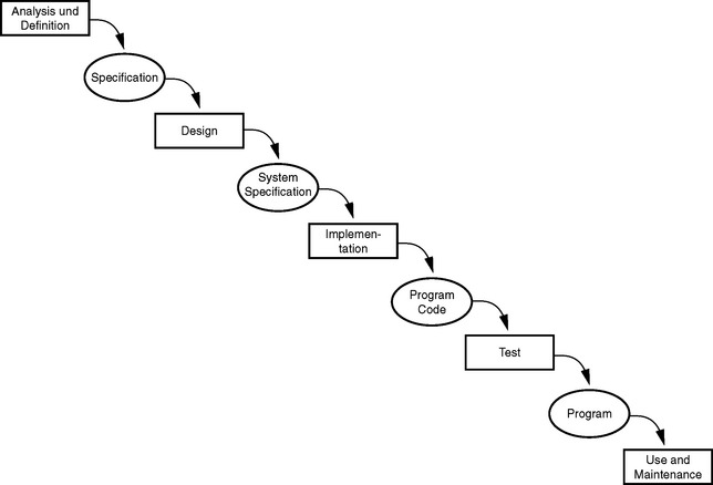
There has been a great deal of criticism of waterfall models (see for example Budde et al. 29, Parnas and Clement 85, Pomberger and Blascheck 96). The key problems with this model are that they poorly support application orientation and planning. We can summarize the following weaknesses:
• The activities of the process model are oriented to software technology rather than to the application domain’s interest.
• The linear approach of this model is hard to maintain and plan.
• Essential requirements cannot be identified in advance and change constantly.
• Pure milestone documents are not reliable results, because their consequences are difficult to predict.
• The model does not consider developers’ learning processes, and no prototypes are available.
12.1.4 The Spiral Model
The spiral model (see Pamas 88) is regarded as an important improvement to the waterfall model. However, we think that it creates similar problems.
DISCUSSION
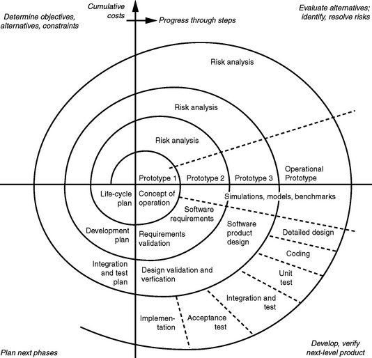
The improvement represented by the more flexible spiral model over the waterfall model is also based on named and standardized development steps. However, these steps are repeated multiple times within a process, until the product is completed (see Figure 12.3). Though the spiral model includes a cyclical alternation between the activities involved and integrates prototyping to deal with the difficulties of identifying requirements, we think that its concept has the following flaws:
• The model sees the object of a development process as a new and self-contained product, as does the waterfall model.
• The model forces you to run the activities involved one after another.
• The model separates software development from use and maintenance.
• The activities are oriented to technologies rather than the application.
12.1.5 An Idealized Evolutionary Process Model
This section formulates an idealized evolutionary process model, that is, an alternative to the waterfall or spiral model. It can be thought of as a fundamental reorientation of the software development process. Each project should reflect this ideal, depending on the individual case.
DISCUSSION
Our idealized evolutionary process model is shown in Figure 12.4. You will probably not be surprised that this model combines the basic principle of the author-critic cycle with application-oriented document types. Two major principles define this process model:
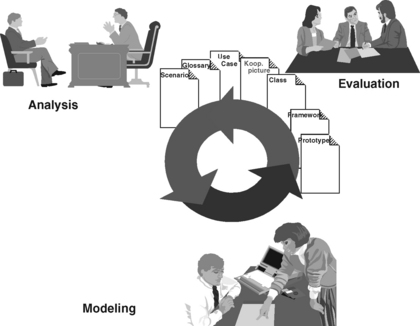
1. The general activities, namely analysis, modeling, and evaluation should be alternated as often and quickly as possible in each software project. This applies to both the development and the management of your project. Special attention should be paid to selecting suitable authors and critics.
2. All document types that we select for a project should be editable during the entire course of the project; there is no predefined processing sequence. Each document type should be selected in view of its purpose and how easily it can be understood by both authors and critics.
We can identify the following requirements from the basic similarity between the development and management processes, based on our interpretation of general application orientation:
• Document-based modeling: The development process is based on documents representing a model of the application system (i.e., a “model-driven” approach in the sense of UP). This may not sound like doing something new. However, a
closer look shows that those involved in the process create and evaluate only documents that represent relevant aspects of the application system. This means that each activity should have a purpose, and each document should contribute to the application system. All participants involved in the project should have a clear understanding of which document types are suitable for which target group and problem, and cooperate on this basis. We will come back to this issue in Chapter 13.
As one consequence, we do not use additional documents for the management process. The fewer dedicated management documents developers have to create, the stronger their commitment to the development process. Therefore, development documents should be systematically used in the management process. Naturally, this does not mean that you won’t have to deal with planning documents in the evolutionary approach. We will discuss this issue in detail in Section 12.6.
• Actual and target states adjustment: Software development is not an end in itself; rather it is a service that should demonstrate its contribution to the corporation objective. We know that use contexts and domain-specific requirements may change considerably in the course of a project. For this reason, we often have to adjust our assessment of the current situation and the goals for the system under development. While traditional process models emphasize the target concepts, we stress the importance of documents representing the current situation (similar to UP). Target modeling requires the selection of appropriate prototypes (see Section 13.6 for more details).
At the same time, application-oriented documents and prototypes form the basis of our management process. The more effectively they describe a current situation or vision of the system, the more likely that our management process will be able to check and review the project goals and allocation of resources for our project.
• Constant feedback: The document authors should receive an evaluation of how well their work can be understood and what use quality is expected. This is an important aspect of constructive quality assurance. It means that we assure the quality of a result during the entire construction processes. Quality assurance traditionally tends to be a control process, in which a software product is either accepted or rejected after a special test procedure, that is, when its development is complete. In addition to constructive quality assurance, constant feedback promotes the communication and learning process between the participants. Developers should be in a position to really understand the domain-related concepts and requirements. Section 12.3.1 describes how such feedback processes may look.
For the management process, continuous feedback also means that we constantly check and revise our project plan, using mechanisms similar to those used in the development process. This means that we have to document the management process. We have to record project goals, distribution of tasks, responsibilities, and deadlines, in documents accessible to all involved. Moreover, all activities should be checked regularly by those in charge. As a result, we may have to introduce new goals and steps. This means that the management process is subject to author-critic cycles similar to those involved in the development process.
12.2 TOPICS FOR A DEVELOPMENT STRATEGY
Software projects normally raise similar questions: Which development activities are meaningful and when? Which types of programs can be developed in separate work steps? Can the project be organized on a decentralized basis? Who should we involved in the project team, and how should we organize the team? Which organizational form would be most suitable?
We have compiled the list of topics in the following section based on our experience with many software projects.
12.2.1 Sequence of Development Activities
Many critics of evolutionary process models argue that the sequence of development activities must always follow an inner logic, such as that design comes before construction. On the contrary, we argue that specific projects can and should specify a sequence of development steps, but not in a general process model.
DISCUSSION
It may seem logical that requirements should be analyzed first and a design should be created before we build a product. Without discussion, software projects involve basic work steps (e.g., editing, compiling, versioning, documenting), handled in a particular sequence. However, the “who,” “what,” and “when” in a project do not follow a fixed (software-motivated) life cycle scheme, but rather should be oriented to the circumstances of the application domain. Many critics argue that there is a certain technical “subject logic” that by nature follows a waterfall approach. This is true for the microlevel, where it actually makes sense to think first what a piece of a program should do and how it should be structured, in terms of architecture, so that it can eventually be implemented and tested. However, these constraints apply less frequently on a broader project level. The Unified Process, with its parallel arrangement of activities, takes this into account. The following criteria are important when we try to identify activities and their sequence:
• The activities are not allocated to separate work steps or project phases.
• Each activity refers to a specific goal, that is, it is application-oriented, and takes the underlying technology into account (see Section 12.5.1).
• Modified domain requirements should continuously be taken into account to determine activities.
• Documents are not allocated to specific activities, which means that they will be updated whenever necessary, rather than “frozen.”
• The learning process of all participants is supported by integrated project teams, but primarily by feedback from application-oriented documents and prototypes.
EXAMPLE
In one of our projects, the developers decided not to take the conventional approach, that is, to begin with an analysis of the application domain. Instead, they constructed a technical prototype on a totally vague domain basis, showing little more than basic interactions at the user interface. Later on, they began familiarizing themselves with the situation and the requirements of their application domain by conducting interviews and attending lectures and seminars on the subject matter.
This approach was taken for the following reasons: First, it was the first time this team used Smalltalk as their development platform. Second, they felt that potential users in the application department didn’t think much of the capabilities of their development department, because they had been disappointed with previous software projects.
For these reasons, our development team wanted to make sure that they mastered their technical tools before they addressed activities in that application domain, which was new to them. As the project progressed, this decision proved to have been right for that situation.
12.2.2 Objectifying the Development Process
We have said that software development is a document-driven modeling process. This statement raises the question of whether these documents may be the best prerequisite for an objectified development process. The aim is to substitute team members freely or to allocate analysis, design, and programming to different people. Our answer is that an objectified form of development is not feasible for most parts of an application system.
DISCUSSION
Objectification of the development process is often propagated as the software engineering idea, including the idea of creating software so that it can be produced by different people; in other words specialists with different qualifications and experiences (and different rates) should be used for the different sets of activities involved in a process model. For example, analysts would create the domain model, designers would produce the software design, software ergonomists would design the user interface, and programmers would write the actual program code. In addition, maintenance programmers and customer service staff would be available for post-development work. Another popular goal is to gain personnel independence within the groups involved; people who leave should be replaced without negative impact, and scheduling bottlenecks should be resolved through additional staff.
Project documents (e.g., milestone documents) should contain all information about the step currently worked on and the next step to ensure that this division of labor and objectification will work. For this purpose, the documents should be unambiguous, consistent, objective, and formalized to the widest possible extent.
We think that these are illusionary traps in traditional software engineering, connected to two problematic assumptions:
1. Software is a solution for a given problem similar to solutions for problems such as mathematical equations. This is true for a small number of cases only, where problems can be described precisely, as in mathematics.
2. We can write unambiguous specification to have software built by different people and in a depersonalized process similar to a production line. This assumption doesn’t hold for most development projects.
We argue against this view with the philosophy that software development is first and foremost a communication and learning process between the people involved.
This is the only way that allows developers, who are not experts in a particular domain, to gain the knowledge required to fully understand the activities in the application domain and how they should be handled. Practically speaking we cannot let others do the learning for us. Developers will be able to develop high-quality application systems only if they understand the tasks and concepts of that application domain.
The system under development is not a “unique” solution to a well-defined problem. The groups involved have to negotiate the tasks to be dealt with in the future and ensure that these tasks are supported in the development process. Normally, we can specify only some aspects of this process in sufficient detail to produce documents that serve as a secure work basis for the team. The experience, views, and values inherent in each development project cannot be represented in documents. We summarize the resulting dilemma as follows.
A software system should be formally documented, and these documents should be consistent, correct, and complete. On the other hand, both the goal and purpose of such a system cannot be described fully and objectively.
What impact does this dilemma have on cooperative software development? It would be naive not to allow a division of labor in a software project, expecting that the same people will work on it from the beginning to the end. In fact, this naive assumption contradicts our way of thinking. After all, we want to present the T&M approach as the appropriate basis for cooperative software development. This includes the fact that different people and groups are involved in the design and construction of system components.
The following section explains why the classification into S, P, and E programs proposed by Meir M. Lehman is helpful. Related to objectified development, this classification means that different program types can be described and implemented on the basis of a division of labor, with different degrees of success.
12.2.3 Lehman’s Software Classification
The software classification proposed by Lehman is useful in describing the degree to which software can be developed based on written specifications. Lehman distinguishes between specification-type programs (S programs), problem-solving programs (P programs), and embedded programs (E programs).
BACKGROUND
Lehman proposes the following classification for software:
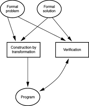
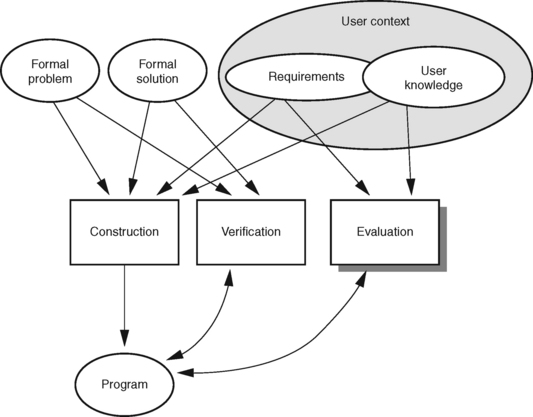
• The characteristic of S programs (cf. Figure 12.5) is that there is a complete, formal specification describing well-defined problems and their basic solution. Examples of such problems include sine calculations and the Eight Queens problem. This means that we can normally define what an S program should achieve, regardless of a particular situation or use. The prerequisite for such problems and solutions is that they have to be generalized or abstracted before you can represent them formally in an objectified mathematical form. Using a mathematical method, we can then check whether or not the S program can be fully derived from its formal specification. This kind of verification can be achieved for a small number of well-known problems. Date-checking routines and model calculators to compute results are application-oriented examples of using S programs in real-world projects.
• P programs (see Figure 12.6) are based on clear tasks, that is, they can be specified and solve a known problem. In some cases, P-type programs may even allow us to formally describe a task, which means that they relate to S programs. Chess and other games are good examples of P programs. They differ from the S program in how they solve a given problem, which must first satisfy the formal conditions of the task. For example, a chess program may not make a move that would be against the rules. In addition, we have to specify how well, or at what speed, precision or capacity, a P program should solve its task. This decision is normally taken by the developers, but ultimately evaluated and accepted by the users. For example, a novice will have different requirements for the performance and response time of a chess program than a master player. In the context of our projects, we often find P programs in place, for example to check the completeness and consistency of forms. A domain expert can easily tell what a consistent form is, and we know that an inconsistent form cannot be used officially, such as for contracts. On the other hand, when things should be checked and with what effort and precision is normally hard to define before the application is used.
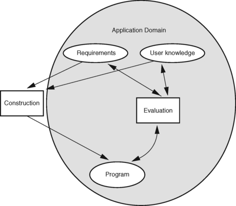
• E programs (see Figure 12.7) are developed to support an application domain, for example in specific work situations. This means that a subjective aspect is already included in the conceptual definition of an E program. Whether and to what extent a state is considered a “problem” and what type of support is required depends largely on the observer’s view. Consequently, it will be hard to find something like a self-contained and objective specification of a task or problem. This is the reason why solutions or algorithms are not defined abstractly for E programs; instead, they can only be evaluated and accepted by the participants. An office automation system is a good example. There is no abstract way to tell when and in what situation such a system is a good solution for a problem; even identifying something as a problem depends on the participants and their tasks.
Correctness in a mathematical sense cannot be demonstrated for E programs. Whether or not an E program is right for a given work context and the people involved is a more important question. Most of the examples given in this book are E programs according to the classification here discussed.
DISCUSSION
What is the meaning of Lehman’s classification in relation to objectified software development? It primarily means that the program types can be described and implemented in different ways. In a traditional sense, S and P programs are well suited to specify an objectified basis. This is not the case with E-type programs, that is, we need to understand the parts of the context and work situation of an application system that cannot be formalized to be able to develop E programs.
In addition, the evaluation of S and P programs has different requirements. Although we can easily check S programs for correctness, this is difficult for some important properties of P programs. On the other hand, the evaluation of E programs is an ongoing process between all participants, since both the evaluation and the use may introduce changes to the requirements during our development process. In fact, new operative components and expansions change the team’s and, even more so, the users’ ideas about the application system. For this reason, it is important to achieve a high degree of continuity in the developer team to ensure evolutionary adaptation of the system as the requirements change.
12.2.4 The Cooperative Development Process
Application software is developed for different use contexts. The T&M approach normally supports different workplace types, as described in previous chapters. At the same time, it is important that existing components should be reused for workplaces in our system under development. This means that we have to deal with issues related to distributed development.
DISCUSSION
Lehman’s classification of the development process in S, P, and E programs is helpful for finding an answer to the question of which elements we can create for an application in separate steps or by different teams within our development process. Suitable system parts are those we can specify as independent domain or technical services in the context of a workplace concept. When we have to develop a new service, then we need to clearly understand the application context. This is the only way to implement a service independently. One example from our own projects is the implementation of a workplace system, which was connected to a large host-based customer management system, in separate steps.
However, we have to understand that the implementation of system parts by independent work groups always represents the starting point for subsequent joint design decisions. We have to bear in mind that each new system element changes the context that integrates other elements. The E program concept shows clearly that it is not enough to identify a service and implement it to complete a development process. We also need to do evaluations and obtain user acceptance to complete the cycle, since only the actual users can finally approve the system elements and services. This means that our understanding of E programs is based on the interplay between construction and evaluation. It also means that we need author-critic cycles throughout our development process to define and evaluate subtasks constantly.
The classification into S, P, and E programs also shows whether and to what extent external cooperation partners or subcontractors can adopt components. In fact, this classification shows that S program can generally be defined as separate tasks. For example, an application component for a banking application can be specified with reasonable complexity to calculate different types of credit ratios.
P-type programs are suitable for loose cooperations, but the cooperation partners should have sufficient expertise, and the components should be integrated and evaluated in regular intervals. A good example are the elements used for chart analysis in a bank’s securities management system. This involves balancing the financial parameters against usability and manageability requirements.
In contrast, complex E-type application systems require a very high level of constant coordination and feedback in a project team and with users, so that they are hard to develop in distributed projects. Therefore, although system parts of E-type application systems can be developed as independent services by different people “in-house,” it is rather unlikely that they will be suited for subcontracting to third parties.
An important management function in each development organization is to identify separate S and P elements within the entire application system under development. These elements can then be implemented jointly by cooperation partners and external contractors in separate steps. However, there are always risks inherent in this approach. Experience with formal specifications has shown that the effort required to create such a specification usually exceeds the implementation effort. For this reason, the corporate management should be careful to avoid having the preparation and assessment of external orders consume more internal resources than absolutely necessary, in comparison to developing the system part in-house.
If an organization has exhausted its possibilities for outsourcing the development of system elements, and there are still scheduling and manpower bottlenecks, then the organization could choose an insourcing option (see the following Section).
12.2.5 Organizational and Domain Integration
Project teams should be formed so that there is a high level of personnel continuity and different expert knowledge. Minimum staff fluctuation in a development process is a prerequisite for the learning processes involved, and it helps build a solid basis for systematic work based on documents. The domain integration establishes the application orientation and should reflect changes in that domain. The options available to use external developer capacities could also be evaluated against this background.
DISCUSSION
We think that the ideal of objectifying development documents as a basis for project organization is not a good idea, because objectification should not become the primary principle of a project. In practice, dividing a project into separate self-contained steps for independent teams does not produce the desired results. Instead, we encourage the use of integrated developer teams, composed of domain and technical staff members, and strive for continuity of personnel within a project. This means that the same members of all groups should ideally work in the project team throughout the entire project.
This integration and continuity should extend beyond the individual project. Our project experience has shown that a development culture should unfold that influences the entire software development, and it should not disappear once a project is officially completed. For example, we see an architectural group (see Section 12.2.6) as a catalyst for a common development culture. It can ensure continuity beyond an individual project, based on its experience and knowledge of the context.
Of course, not all team members are normally able to handle each task in a project with the same skill. There is always the likelihood that some expert team members won’t be available for the entire project. Nevertheless, we should try to solve the problem; purely technical skills are not sufficient to develop application software on the basis of written requirements.
ORGANIZATIONAL INTEGRATION
Organizational integration is one solution to solve the continuity problem. The “relay principle” is applied to projects and “project families.” When athletes run in groups during a relay race, they make sure that a pole will be handed from one runner to another. Similarly, each project allows sufficient time for “overlapping” staff when personnel changes occur. During this period, the departing team member and the new employee exchange information about the project directly. This is a primary prerequisite for a good understanding of the project and development documents.
INSOURCING
A valid mechanism within organizational integration to work with external partners is insourcing, or local presence.
Insourcing means that external partners cooperate with the development team. The prerequisite is that the development style of these external partners is compatible with the method selected. The people concerned should not be substituted at will, nor should they be given other tasks. We have acquired some useful experience in various projects, where external advisors, who were not familiar with the application domain and the T&M approach, were used for programming support. The external partners worked in pairs (see “Pair Programming” in Section 12.3.4) with two or three team members, helping them to solve existing construction problems.
Pair programming is a good means of transfering the knowledge of external experts into a project.
EXAMPLE
A Smalltalk development environment was supposed to be applied to a banking project. The team involved was not familiar with Smalltalk. Although the members of the team received training, it soon turned out that problems were occurring—particularly with the use of the GUI tools and visual programming components. To solve the problems, a six-month contract was signed with a consulting firm that had already carried out various Smalltalk projects with this environment. A consultant was available to the project three days each week. Each day the consultant worked with a team member at the person’s workplace. The in-house person would explain the current construction problem, which the consultant then solved jointly with the team member. This resulted in a dramatic reduction in the development time for the application components and a considerable increase in construction knowledge in the team—without the need for writing complicated specification and requirement papers and the formal acceptance of externally created components.
COORDINATION PHASE
If a local presence based on the insourcing principle is not possible, then preplanned and continuous coordination is essential between participants. It should be noted that communication media such as E-mail, telephones, and video conferencing are usually an unsatisfactory substitute for direct cooperation between people. A modified form of insourcing can be helpful, with an experienced team member working for a substantial period of time on the team of the external partner. Our experience with this approach is, however, not as good as with actual insourcing. Problems often occur when the two projects subsequently start to proceed differently. Different views about the need of feedback cycles and the significance of documents have a particularly detrimental effect. Subcontracts to partners in the form of so-called “fixed-price” projects in this connection have a universally negative effect. We found that there is always a disparity between the expectations and conceptions of the client and the readiness of the contractor to meet these requirements. As a result, both parties are dissatisfied with the project result, and an atmosphere of mutual distrust instead of a cooperation will prevail during the course of the project.
DOMAIN INTEGRATION
The domain integration has to be added to the organizational integration of personnel. This integration relates to the developer organization structure and the work style in the application domain.
What has happened in many developer organizations is that the organizational structure of departments and domains, such as sales and central and distributed development, has sometimes created considerable friction in projects that work with application-oriented and evolutionary project strategies. Thought should therefore be given to avoiding this separation at the project level and within a project family. The specializations required of individual team members and the different knowledge each of them has to contribute must be used in a beneficial way in domain-integrated teams.
In contrast, we still find a department-oriented project organization, where certain activities or project types are only handled by the employees of a specific department, which does not only apply to development. Experience shows that this approach is also important for bug fixing and further development.
Projects in which interactive workplace systems are being developed are those that particularly end up in a dilemma. On the one hand, in accordance with the principles of eXtreme Programming, all team members should be able to master all aspects of a project. On the other hand, due to the growing number of complex technologies, it is necessary that different types of knowledge about technologies are represented in the project team. XP designates the role of a consultant here. Even independently of XP, individual team members will specialize in areas like interactive software development, distributed systems, networks, databases, and mainframe applications. Although it is sensible to have specialists for the different technology and application subjects, it is important to disseminate knowledge about these subjects to all team members in a project so that they can use it meaningfully in application development.
Technical integration in a developer organization must be appropriate to the domain integration. There are obvious trends, at least in the financial services sector. The common factor is an application orientation that today is referred to as customer orientation. What is meant is the tendency in businesses that deal directly with customers to move away from the traditional separation of business sectors and instead be customer-oriented, thus providing more comprehensive individualized services. In other words, the processes and the organization of a company or enterprise should be oriented to the customers in order to guarantee maximum customer satisfaction. In addition to the generalization this requires, the signs are that specialization in the consulting and marketing areas will always exist for dealing with very demanding services and products.
The “natural” allocation of projects and development activities along the traditional product lines and departments of the user organization must therefore be rethought. In Sections 12.2.6 and 12.7, we describe how this affects the design of applications software. In summary, we have to form integrated teams to guarantee consistency in the development documents and eventually the usage quality of the application system. These teams should consist of members with domain and technical expertise.
EXAMPLE
Customer orientation in banking is shown through the merging of savings and credit customer account services, tellers, and the securities business in service centers and the imminent integration of cross-selling products (e.g., insurance, property, mortgage services). There is a trend that new workplace types, such as professional customer advisory services, standard consulting services, teller services, and self-service facilities, emerge in the customer area. On the other hand, the traditional product-oriented or business line separation may well be retained in the back-office area in the near future. In the middle, we find controlling and monitoring activities, where customer-centered and product-oriented access probably needs to be combined. These different trends are leading to different use contexts in which customized workplace systems are being developed. Yet these systems must be developed with the same domain and technical basis. Here, the architectural concepts explained in Chapter 9 can help.
The best place to start a family of projects is with the customer-oriented workplaces, because this is where the new orientation is most obvious and is the easiest to evaluate its repercussions on other areas.
12.2.6 Developing an IT Organization
Evolutionary system development based on the T&M approach usually has consequences for the developer organization. If several object-oriented projects or whole project families are to be organized in one company, then it appears reasonable to use frameworks or component technologies. This requires further changes to the organizational structure, and consideration should then be given to establishing an architectural group and a team for product planning.
DISCUSSION
The establishment of application-oriented projects for the development of an interactive workplace requires changes to the developer organization. Our demand for technical and organizational integration can seldom be implemented smoothly into existing organizational structures. In practice, the mere question regarding which department is to provide the project management and how team members from various other departments will report to this management is enough to cause difficulties that can hamper the progress of a project.
Our concept of a core system with extension levels (see Section 12.7) transcends these organizational issues. Today, such a system with its different workplaces and components should actually be constructed through the use of (application) frameworks and component technologies. Section 12.7 describes the relevant domain and technical concepts. This section discusses the consequences for the organization and the management of the total process. It should be noted that only very few developer organizations have made the transition from conventional to application-oriented and evolutionary software development. The following observations are based on experience and provide some clarity about the trends described.
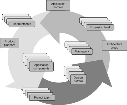
Figure 12.8 shows the interplay between design patterns, frameworks, and application components in the development of an application system with different extension levels. The framework architecture is the key to the technical and domain-related integration of the application system. Different actors (or “workers,” in UP terms) are necessary to put this into practice.
The role of the application domain as the central domain instance for application development in its different aspects is described extensively in this book. Here we want to emphasize that the application domain fundamentally defines the requirements of a system and establishes its usage value.
PROJECT TEAM
The development of the application components that make up a system’s extension levels is carried out by project teams. Together with the product planners, the application software developers form the core of every application project. Individual experts that come directly from the application department and one or two software architects are part of this core. These integrated teams design and implement the respective application systems or components. The principle of continuity in personnel is applied. This also means that a high percentage of the project members work on only one project and continue doing so. Having a person work on several projects at the same time has proven to be counterproductive.
Along with an understanding of the domain and tasks and requirements, a solid technical foundation is necessary for project work. It is mainly the application developers who need a grasp of these fundamentals. But it is also important that the other team members have an elementary technical knowledge.
The project work encourages further development of frameworks and components and the formulation of new patterns.
PRODUCT PLANNERS
The design of an application system with its components and extension levels depends not only on actual requirements of the application domain. What is also important for the organization in which the developers work are the strategic decisions taken during the development of a product line. The responsibility for this lies with a department or with a group of people we call product planners. These product planners coordinate the development of new application components and the use of different extension levels, based on domain requirements and corporate policies.
Consequently, this group finds itself in a position of conflict, balancing user requirements on the one hand and the technical feasibility and the strategic concerns of the developer organization on the other. These team members need to be well-qualified in various fields. The ability to communicate is the main prerequisite for merging the different interests. Domain knowledge is obligatory. In addition, a solid understanding of the technical concepts of object-oriented application development is needed. Accordingly, conceptual patterns represent an important element in the language of product planners. It has also proven useful if product planners have some basic programming experience and are even able to construct presentation prototypes themselves. The existence of these capabilities noticeably helps to improve cooperative work with developers and architects. Lastly, it helps for this group to have a feel for company strategy and management capabilities.
ARCHITECTURE GROUP
A framework-based architecture is the backbone of the type of application development described here. The conceptualization and development of this architecture is the responsibility of, what Ivar Jacobson has called, the architecture group. As described in Section 9.3.7, the architecture specifies the basic technological concepts, the principal tool construction, and, above all, the main domain concepts of a system. From its view of the entire system, the architecture group has to initiate the domain-oriented coordination between the projects through the main concepts of the business domain (see Section 9.2.3). It has to ensure that these concepts form a consistent foundation for the entire system.
Software architects represent the software-engineering viewpoint in application development. However, they also have sufficient domain knowledge to find the abstractions needed for the further development of frameworks and the “distillation” of domain components. To ensure that their knowledge and experience is reflected in the project work and can constantly be updated there, architects also always work as senior consultants in application projects. They are used there during design and implementation as well as for selected management tasks. However, they should not function as project managers. The domain-oriented architects are assisted by selected technology specialists, recruited for the implementation and further development of the technology basis across all platforms.
The architecture group is responsible for the architecture management of the whole project. Architecture management can be divided into a domain part and a technical part. Both parts form the architecture’s core. This system core is the prerequisite for constructing a family of application systems and enabling the reuse of concepts and components. The technical architecture management concerns itself with those requirements that concern the constructive basis for the domain-related projects.
The cross-project tasks of the architecture group include glossary management (see Section 13.4), plus the management of cross-project concept models and the entire glossary. This cross-section function is an important prerequisite for presenting users with a consist domain-specific taxonomy that extends across all integrated application functions. It requires project members to acquire a common work language that can be applied to several projects. Glossary management monitors the consistency of the terms used in the work language, building a foundation for a coordinated domain-related architecture.
Another important responsibility of the architecture group is to maintain close cooperation with product planning. As goals and priorities are established, the architecture group has to clarify which development options are possible considering the current state of technology and architecture as well as the current project activities.
This discussion shows clearly that high demands are expected from the architecture group members. Only developers who have extensive experience should be part of that group. In addition to excellent software engineering knowledge with a solid theoretical or conceptual basis, they also need sufficient domain knowledge. Communication capabilities also appear high on the list of priorities. Of course, this describes an employee profile that only a very few are able to fit—or as someone recently quipped, “software gods.” But we want to make clear that the requirements for application-oriented software development using frameworks and component technologies are ambitious. Each developer organization should therefore examine whether existing personnel resources can meet such a challenge. In summary, Figure 12.8 shows a cyclic process that integrates different participants and development results.
12.3 QUALITY ASSURANCE IN THE DEVELOPMENT PROCESS
As a professional product created by cooperating groups, the quality of application software cannot be regarded independently of the process that developed this product. We therefore present different measures that can guarantee the quality of the process. These measures “build quality” into the product.
The proposed measures influence different groups involved in the development process. Direct user integration, prototyping, and informal reviews are carried out by project team members in conjunction with the users. Formal reviews, pair-programming, and refactoring are techniques used within the actual developer teams.
12.3.1 Direct User Integration
In the T&M approach the author-critic cycle (see Section 5.3.4) is the key for integrating users. As a feedback technique, the author-critic cycle encourages communication and the learning process between the groups participating in the project. Thus the quality of model elements can be checked and improved, if necessary.
DISCUSSION
The author-critic cycle demands constant alternation between analysis, modeling, and evaluation. During these cycles, project members design models by writing documents, diagrams, and program code. The authors of the different models must receive feedback about how easy their work is to understand and about its level of domain-related quality. This is important for constructive quality assurance. Critics enable an author to improve the quality of his or her models and to add new model elements. The general principle guiding the author-critic cycle says that authors and critics should be different people. The best experts available should be selected for critics roles. In the sense of usage quality the critics often have to evaluate not only the domain-related correctness of a model but also whether the modeled system part provides appropriate support for day-to-day work. This kind of assessment can usually be best made by the users themselves.
For cooperative work with users, developers select those document types that directly relate to the users’ work, such as scenarios, glossary entries, cooperation pictures, purpose tables, and, to some extent, visions (see Chapter 13).
Other representation means, such as most UML diagram types of the software model and the program code, cannot be assessed by the users. These model elements are authored by a project member and then turned over to technical experts, such as database administrators, or other project members who act as critics. Again, critics are used to improve the quality and open the door to overlooked issues.
The author-critic cycle should consist of short time periods to allow authors and critics to be in constant contact. These short cycles should ideally be repeated until all participants have reached a common understanding of the current problem and its potential solution. This enables model elements to be developed in an evolutionary way and to achieve improved quality at the same time. Of course, we have to plan these cycles within a realistic time and resource frame (see Section 12.6).
12.3.2 Prototyping
Prototyping is the key feedback process for system evaluation, involving both users and developers.
Different tasks within our software development process may be supported by prototyping, including project initiation, application domain analysis, and the design and construction of the application system. One or several kinds of prototypes (see Section 13.6) will be well suited for such tasks.
DISCUSSION
Prototyping has been a well-known and proven technique in software development for a long time. It is something that cannot be dispensed within an application-oriented approach, because there are few other means available for users to evaluate a system under development. Yet simply programming an executable piece of software is not sufficient.
Prototyping should always be related to a specific problem—the one that the prototype is supposed to deal with. The problem must be defined clearly before the prototype is constructed. This prevents a situation where aspects for which the prototype was not designed are evaluated after we built the prototype. If the problem is not carefully defined, there is the danger of “muddling through.” In other words, we build executable software versions and, if people like them, they are accepted as a success, but if they are not well received, they are discarded with the attitude “it was just a prototype.” Different kinds of prototypes address certain problems (see Section 13.6). For example, no meaningful performance tests can be carried out on pure presentation prototypes.
Different kinds of prototypes are normally built during the entire development process. In large projects, we use the whole spectrum of prototypes, depending on the problem. However, this means that prototyping is not simply reduced to just another phase in the development process.
Prototyping, as we see it, is strongly focused on domain-specific problems and the usage quality of the software system. But this should not rule out the importance of the software engineering aspects and the demands on the architecture. Therefore, a methodological approach should be applied to allow for refactoring in the prototyping process. This means that existing functional prototypes have to be revised from a software engineering view to create a solid basis for evolutionary prototype development towards the target system (see Section 12.3.5).
In contrast, presentation prototypes are normally handled as “disposable” prototypes and retain that character. In real-world projects, we often find that an attractive user interface tempts the corporate management to turn a presentation prototype into the future system platform. Developers should always make clear that presentation prototypes are only design drafts. They demonstrate what the domain analysis and design have produced, but they are not developed for a specific target architecture or for technical quality. Presentation prototypes support the essential learning and cooperation processes in system development and the development of domain-related system visions.
12.3.3 Reviews
Informal reviews are events that are not bound to formal guidelines. We include road shows and user work groups in this category, that is, meetings that provide an opportunity for project ideas and results to be discussed in larger groups. In contrast, formal reviews are carried out in fixed settings and based on certain rules. The following subsections discuss these forms of the author-critic cycle.
ROAD SHOWS
One way to make the project ideas and results accessible to a broad interest group is through road shows. These events are informal to the extent that no uniform rules dictate how to prepare or conduct them. Most road shows are organized in the application domain, so that other people who are not direct users can learn more about the project work. Often, it is also useful to hold road shows within the IT department, for example to invite other developers interested in the project topics. New object-oriented projects in particular tend to create a mixture of interest and suspicion among other developers. Road shows normally represent a good opportunity to motivate these people.
The project team usually decides whether documentation material should be distributed to the participants of a road show before the event takes place. During the event, partial results are presented and discussed. The feedback that project members receive from such discussions can be beneficial for their project work. For the project setting, it can improve the flow of information and consequently often results in higher project acceptance.
USER WORK GROUPS
User work groups are normally composed of a selected number of potential users. These users assume the role of the critics, while the project members are the authors. The project team invites users to these work groups with the objective of obtaining comprehensive feedback about a project result in an early phase. It is important that this feedback comes from a group of users and not from an individual person. Anything that is unclear due to different situations in user organizations can be discussed and clarified in a larger group. Therefore, the important thing is not to have an individual document, such as a scenario, validated by a user, but instead to identify and possibly consolidate different views on a topic.
A user work group should be arranged as soon as an application domain model, including scenarios, and a concept model are ready. These meetings should then be used to create and discuss cooperation pictures to generate a common view of the tasks and processes involved in the particular domain. Similarly, each functional prototype should be presented to these groups so that hints and critical comments can be obtained for further development.
FORMAL REVIEWS
The concept of formal reviews has established itself as a feedback technique in many developer organizations. As the name already implies, this is a review type involving a fixed sequence of activities, in contrast to informal reviews. Formal reviews allow project members to obtain in-house feedback from other colleagues not involved in the project. It is important to guarantee independence between the authors and their critics (reviewers). Consequently, only those reviewers to whom the producers do not have a dependency relationship should be allowed to participate in formal reviews.
The detailed procedure of formal reviews varies according to the organization and its culture. The following rules have proven useful:
• The documents used for a review should be distributed to participants at least one week before the actual review date.
• During the review, all reviewers should first present their positive and then their critical comments, and all comments should be documented.
• A review is conducted by a review manager who has the responsibility to ensure that there is no discussion of content and that the only questions raised are those concerning the comprehension of critical comments.
• Unlike road shows, there are normally no system presentations in formal reviews. It is assumed that all reviewers are familiar with the documents distributed before the event.
• When the minutes of the review are available, the project management meets with the taker of the minutes and the review manager to elaborate a catalog of measures derived from the review. Notes are also taken at this meeting. These notes are then used in planning future stages and iterations.
12.3.4 Pair Programming
Pair programming is an aspect of eXtreme programming that can considerably improve the quality of software development. With this technique two programmers work together at one computer in order to complete a programming task.
With pair programming each pair has two roles. One partner (the driver), namely the one who operates the keyboard and mouse, thinks concretely about how, for example, a certain operation should be implemented. The other partner (the reviewer) instead focuses on the design and implementation strategy. The reviewer controls the syntactic and stylistic aspects and decides whether the chosen approach is promising or whether the problem can be solved in another way. Each pair is formed according to the problem at hand and the availability of staff.
The roles (driver/reviewer) in pair programming should be changed as frequently as possible, up to several times per hour. This allows the work carried out during a day to be very concentrated because of the constant change in emphasis in what each partner is doing.
The physical arrangement of desks and computers is very important for pair programming. It has proven helpful to have the computer used jointly by both programmers placed at the corner of a desk (see Figure 12.9).

In such an arrangement, the two programmers can alternate their roles quickly, because they both have direct access to the keyboard. Alternatively, both can also sit normally at a desk. However, the seating position should not influence the role distribution. The programmers should be able to change roles without changing their seats.
DISCUSSION
Pair programming has several advantages:
• It can improve the quality of the source code, because two people work together. There is a greater chance that concepts and programming conventions will be maintained. Formal and semantic errors are usually discovered right away.
• When pairs change systematically, knowledge about the overall system is dispersed throughout the team. The departure or unavailability of a developer thus has no serious effect on project progress.
• The developers frequently question design decisions. Any blocked thinking or dead ends are avoided in development.
In addition to these advantages, which mainly apply to homogeneous pairs, pair programming can also be used for team training. For example, an experienced programmer works with the new team member in pairs. Two things are important when using pair programming for team training:
• New team members should have good basic programming knowledge; this is particularly important for retraining in a new technology. Without minimum qualification and experience, the gap between experienced and novice team members is too great, with the result that the inexperienced person does not understand the work at hand and is usually too timid to ask questions.
• Experienced programmers should keep an eye on the training task assigned to them. It should be made clear that this task does not focus on development work.
Training in pairs is efficient, but it requires a high degree of patience and discipline from the experienced programmer. We have successfully used this approach in projects and found that the technical and domain knowledge of new team members was quickly brought up to the level of the other members.
Pair programming develops its full potential when used in conjunction with refactoring (see Section 12.3.5), design by contract (see Section 2.3), test classes (see Section 12.4.2), continuous integration, and collective ownership. Continuous integration simply means that sources that have been changed are integrated as quickly as possible. Integration should take place several times a day during the construction phase.
Collective ownership means that each developer may basically change all documents and source texts of a project at any time. The overall project knowledge required for this can be disseminated effectively in pair programming.
12.3.5 Refactoring
Refactoring is meant as an improvement of the internal structure of a software system. This should not change the observable semantics of the program to the outside.
Refactoring is seen as a disciplined approach that allows code to be cleared without building new errors into the software. Refactoring produces a subsequent enhancement of software of design.
When programmers are given the task of writing program extensions, it is up to them to check whether this extension would be easier to implement if the existing program were first restructured. Programmers should continue asking themselves whether it is possible to make a program easier even after a modification has been made. Refactoring takes place in very small steps. In principle, each individual refactoring (e.g., renaming a class, shifting an operation to a superclass) can be carried out in a few minutes. Large refactoring jobs should always be decomposed into small refactoring jobs to allow operative intermediate versions to be integrated periodically.
DISCUSSION
Refactoring is time-consuming by nature. Time pressures in a project often lead to decisions to leave a system alone or to work around a problem. Nevertheless, refactoring should always be considered if a system potentially has a long life span, if it has to be reused and should remain capable of further development. The advantage of refactoring is that it prevents the feared deterioration of a system’s structure. The question of whether refactoring would be sensible should be raised as soon as source code is duplicated.
Refactoring has the following benefits:
At first glance the last point may cause some surprise. However, if you think about it, you realize that a good design helps to quicken the software development process. After all, the goal of developing something quickly is the reason for making a good design. Without a good design, development may proceed quickly for a time, but sooner or later a bad design will slow down the development. It takes a lot of time to find and correct errors. Changes take even longer because one first has to understand the code and then find the places where the code being changed was duplicated. New elements always require more lines of code because places that were provisionally patched have to be changed several times over again. A good design makes sure that software development will not slow down over time. Refactoring thus helps to ensure that software can continue to be developed quickly, because it prevents the architecture of a system from deteriorating. Through refactoring the design should in fact improve with time.
Like pair programming, refactoring has attracted a good deal of attention in the object-oriented community in recent years. Historically, refactoring has been used primarily in Smalltalk programming. In his book Refactoring: Improving the Design of Existing Code, Martin Fowler compiled a catalog of refactoring procedures, which supply simple step-by-step directions for improving suboptimal designs.
12.4 QUALITY ASSURANCE IN CONSTRUCTION
Besides the factors that assure the quality of a software product in the process, there are procedures and techniques that relate directly to the product itself. Design by contract (see Section 2.3) plays a key role here. It is used as early as in the domain design and is reflected in the concrete programming.
Along with design by contract, testing can become an important form of constructive quality assurance. This is where design by contract and aspects of eXtreme Programming can be merged.
Lastly, we take a look at the state modeling for the design of those classes that incorporate the concept of a business process. Design by contract is also important in this connection.
12.4.1 Characteristics of OO Testing
Compared to classic imperative programming, object-oriented (OO) programming has some structural and dynamic particularities that have to be taken into account in designing our tests. Testing object-oriented programs is an extensive topic, and we can only provide an overview here. We refer our readers to the seminal work of Binder for more detailed information.
ENCAPSULATION
The smallest constructive units of an object-oriented program are classes. A class has operations that are different in character from the classic subprograms in modules. In class construction the specification (interface) is separated from the implementation. The specification is visible as the interface of operations to the class’s client. However, an operation can be implemented by more than one procedure in different classes.
The procedures differ from classic subprograms in that their coupling (over jointly used objects or through mutual calls) is much stronger. Due to a number of dependent elements, the complexity inherent in classes is higher than with typical functional modules.
A class not only encapsulates a number of procedures, it also normally contains data that models the state of an object. The state of an object is determined by the values of its attributes. Most of these values are references to other compound objects, rather than primitive data. Moreover, polymorphism can be used to bind differently typed objects to identifiers, resulting in a large state space.
In summary, this means that the smallest testable unit that makes sense in object-oriented programming is an operation in the context of a class.
INFORMATION HIDING
We can use the principle of information hiding (see Section 2.1.6) to encapsulate the implementation of the operations of a class. This is a valuable principle in software engineering, but it makes our testing of classes more difficult. In our experience, pure black-box tests cover only one-third to half of the states or execution paths that a class can have, because the test can cover only the structure visible externally.
When developing tests, however, we often need to know the specific state space that an object can have, the embedding structure of a class, and the resulting dependencies. Consequently, we need direct access to the encapsulated state of an object. A class should offer a sufficient number of access functions to allow tests to identify an object’s state.
COMPLEXITY AND DEPENDENCIES
Object-oriented application systems are constructed from objects. Objects communicate with one another and influence each other’s state through the exchange of messages. Whether and how an object will react to a message is defined by its own state or by the state that it can observe on another object. This means that objects are able to form a time-dependent network of communicating units with several “entry points” at runtime, but without a central entity that monitors the control flow. This clearly complicates the testing of control flows in such systems. For example, Binder proposes higher techniques, such as the use of stubs, mock types, and dummies, to deal with this problem. These techniques let you create a test context for the object under test, without the need to reconstruct the entire system environment.
At a semantically higher level, design patterns are helpful to identify dependencies and communication relationships between classes and test strategies.
INHERITANCE AND POLYMORPHISM
Inheritance and polymorphism (see Section 2.1.20) make testing more difficult. As a result, the specification and implementation can end up being distributed over several classes. In particular, the structure of the source text no longer reflects the control flow, which cancels out one of the key arguments in favor of structured programming. “Where are all the places an implementation is used?” and “Was an operation redefined somewhere?” are some of the typical questions in connection to object-oriented testing.
The principle of information hiding is largely eliminated in an inheritance hierarchy. Unless visibility is restricted, a subclass has unlimited access to all features inherited from its superclasses. Consequently, all features of a class and its superclasses have to be retested. This is the only way to ensure that no unexpected side-effects can occur in the context of a new class.
Semantic differences between inherited and redefined operations are not seldom and may surface only in specific contexts. Even if the pre-conditions and post-conditions remain textually equal, they can have different meanings in the superclass and a subclass.
Abstract classes are a special case in that they won’t let you instantiate test objects without implementing abstract operations. This means that we cannot test them dynamically, unless we do some additional implementation work. All operations implemented in subclasses must be checked against the specification of their redefined abstract operation.
Polymorphism requires special consideration in connection with inheritance. Many parameters and return values of an operation reference objects. In statically typed languages, they can reference objects of all polymorphic classes, and testing has to ensure the compliance of these classes with the specification.
This may lead to a situation where errors occur within a class, A, which uses an operation of class B that was redefined in a subclass C. In practice, design by contract can help eliminate these problems to some extent.
12.4.2 Testing OO Programs
The special structural and dynamic features of object-oriented systems have some consequences for testing. We will take a look at the class test, the integration test, and the regression test. We conclude by explaining the concept of test cases and test classes.
TESTING CLASSES
We said before that the smallest construction unit is a class.
The large number of relationships known (use, inheritance, association, polymorphism) increase the significance of integration tests for object-oriented programs, for example, to identify cyclic dependencies.
The use of inheritance and polymorphism means that inherited operations are also tested, along with redefined and new operations in subclasses. If an operation was not redefined, the test from the superclass can be used without modification. A redefined operation must first satisfy the tests of the superclass. If the reimplementation of an operation weakens the pre-condition or strengthens the post-condition, then additional tests are needed to check these new boundaries.
If a new class that redefines operations is introduced into a class hierarchy, the test has to find in client classes all locations where that new dynamic type can occur. These classes should then be tested using the new dynamic type.
In practice, there are problems in instantiating the objects of a subclass, so that they can be bound to the superclass tests (number, type, kind of test).
When building complex classes, it is normally a good idea to specify the behavior in a state diagram and use test cases to check for potential state transitions. This requires the use of gray-box tests that know the internal representation of the states.
The problem of information hiding in the gray-box test can be reduced by implementing classes with two interfaces. One is the public interface, which is subject to the black-box test. The object’s state is defined through private attributes that can be probed or changed by protected operations, which can be overwritten in the subclass (see Section 2.7).
In Java, this inheritance interface can be declared as protected. It is also visible for classes in the same package. However, the test classes then have to reside in the same package that includes the classes under test. This is particularly suitable for testing auxiliary functions of complex algorithmic operations.
The construction of class teams and tool classes leads to complex control flows. Different design patterns that regulate the control flow are examples of patterns that are used (e.g., mediators, events, chains of responsibility, adapters, template methods). These are often based on abstract classes and their specialization. Testing the correctness of the control flow is problematic.
The following strategy is recommended for gray-box tests: The tested classes are implemented and modified in a derived subclass in such a way that we can track the control flow (additional collector parameter in the operation call). Stubs should be developed for the classes used. In the test class, the network of the tested class and its stubs is instantiated and linked together. When operations are called, the test class passes a collector parameter, and each successively activated operation or stub registers with this parameter. The test class can then check the resulting list.
Tim Mackinnon et al. propose the concept of mock types. Based on this concept, the state of a class should be manipulated and probed exclusively through protected getter and setter methods. This makes tests of the state model more reliable. In addition, it reduces the chance that modifications of the underlying implementation of the state model in subclasses jeopardize the correctness of inherited methods.
Classes should be organized in subsystems that are relatively autonomous in the way they provide their services and are loosely coupled with other subsystems. This reduces the number of control flows to be tested and the possible side-effects.
INTEGRATION TESTS AND REGRESSION TESTS
The classic waterfall model (see Section 12.1.3) commonly used in software development distinguishes clearly between integration and regression tests.
The boundaries between these two kinds of tests blur in evolutionary object-oriented application development. The same also applies to class and integration tests. This is due to several reasons.
First, it is difficult to localize the effects of changes to the code (polymorphism, control flows); second, a system develops during several evolution cycles, which means that “maintenance” is necessary early on in the process. For refactoring to be consistent, tests must constantly ensure that the changes implemented do not have any effect on the system functionality.
TEST CASES
For constructive quality assurance it is important that programs are constructed and tested in parallel. Test cases can be written on the basis of domain-specific analysis and design documents (see Chapter 13) and contracts.
Tasks and business processes are described in scenarios and system visions. This reveals the activities to be supported by the application system. Application tests can be conducted on the basis of these descriptions. The situation is similar with screenplays (see Section 13.6.1), which describe a realistic mix of activities at a workplace. Screenplays can be the basis for end users to run application tests. Business and use case diagrams that clarify the overall domain-related scope of the application under test are another means that can be used for these application tests.
Feature acceptance tests can be specified effectively on the basis of detailed system visions (e.g., tool visions) and contracts for the classes.
TEST CLASSES
A method for systemizing testing known from eXtreme programming specifies a separate test class for each class. It also recommends that test classes be written before the classes that are being tested. It will then be clear which problem is being solved under which conditions before a class is actually implemented. It also ensures that statements are well covered.
It has proven to be sensible to allow testing and programming to follow in quick alternations, so that each new class and operation is tested immediately. At the end of the day, all test cases for an integration should run successfully. Testing should thus become a basic attitude in the development process.
Changes will not be safe unless we have test classes, particularly when refactoring (see Section 12.3.5) is involved. Since refactoring changes the inner structure of software, while the interface remains the same, your tests should run without error after each refactoring step.
Systematic use of design by contract does not make test classes superfluous. While assertions of the contract specify only a part of how an operation is used, such as “extreme cases,” the test class can include other important states and parameter values. This increases the level of test coverage.
In addition, a protocol is used implicitly as the basis for each contract but is not checked explicitly, because each contract relates only to one operation. Critical or illegal call sequences can only be checked in test classes. In summary, test classes offer the following benefits:
• The source code is well suited for further development, because changes can easily be checked for correctness.
• The debugging times are reduced, because errors can be localized more quickly.
• Interfaces become simple, as each programmer prefers to test simpler interfaces.
• Test classes show the use intended for a class by the developer and can be interpreted as part of the documentation of the source code.
A suitable tool like JUnit should be used to automate testing.
STATE MODELING
State modeling is originally either a task in the development of technical systems or a technique in database design for documenting changes of object-like items in database tables. From the object-oriented view, an object actually has a state (the respective bindings of its attributes) that can change while the object identity is preserved. We therefore do not initially need an explicit state model.
This changes when we have to model a business process or workflow that relates to a material, such as a set of documents. In the course of a workflow, the material often adopts domain-specific and defined states. From the outside these states can be observed at the interface. For safe handling of material it is important that certain operations are only allowed in appropriate states. Note that these state transitions are triggered by operations; in other words, they are not set as attributes directly by the developer. It therefore makes sense to elaborate a state model at least at the design level and to clarify the states and transitions through operations on the basis of a finite automaton. State charts have proven an effective representation means (see Figure 12.10 and Harel 87). An explicit implementation of a state model, such as using state patterns, is useful for critical objects.
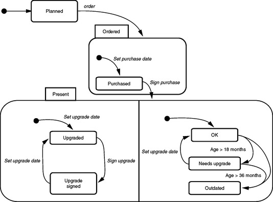
When state transitions with objects manipulated in business processes are modeled, the domain knowledge is transferred to the objects. These objects become more than just data sets. Pre-conditions and post-conditions can also be derived from the different states. It is clear in each state which operations are permitted and which are not. Furthermore, for each operation it can be identified from which source states (relevant for the pre-condition) it is transferring the object and to which target states (relevant for the post-condition).
12.5 PROJECT MANAGEMENT
The literature often sees project management as an independent task that is separate from actual software development. We have found that this is not a good approach for application-oriented software development based on the principles of object orientation. This section describes the relationship between application-oriented software development and project management.
12.5.1 Fundamental Activities of the Management Process
In the evolutionary model, the different activities of the management process are closely oriented towards the activities of the development process. The basic principle of the author-critic cycle applies here as well. Analysis, modeling, and evaluation become planning, steering, and control. In terms of content and scheduling, each project must be planned, organized, and controlled.
PROJECT PLANNING
The objectives envisaged for a project and its various stages (see Section 12.8.2) must be worked out and documented in a comprehensible way. The domain vision for the system is the driving factor in a software project. Management must ensure that this domain vision is compatible with the strategic goals of the company as well as with the available resources and the technology being used. At the level of individual tasks, it has proven useful to allow team members to work out the fine planning themselves.
PROJECT STEERING
There are many ways to manage different project activities. To simplify matters, commonly used management styles can be divided into a process-controlled or supporting style. A process-controlled management style is characterized by orders from above and detailed job specifications. It corresponds to the traditional hierarchical military management style. In contrast, the supporting management style more closely matches our evolutionary approach. Here the project manager takes on the role of coach, spokes person, and service provider for his or her team along the lines of Tom DeMarco and Timothy Lister. The project manager creates the opportunities and conditions that provide the team with an optimal way to work.
Based on eXtreme Programming, we recently tried “pair managing” in large projects and project families. In pair managing, two project managers of equal rank work closely together in the steering of a project. Along with receiving better feedback on their own work, another pleasant side-effect of this approach is that the project managers still have the time and opportunity to get involved in the content of the project subjects.
PROJECT CONTROL
A careful assessment of the situation is an essential starting point for each cycle in the management process. The current situation in the application domain is as important as the situation in the project itself. As a result, for the control aspect it is of prime importance to evaluate the domain documents and compare them with the current situation. The planning documents are checked to ensure that decisions are followed and activities put into action correctly. Here the separation of roles between authors and critics plays a particularly important part. Real-world projects have shown that it is useful to have team members plan and run project meetings related to these topics.
THE INTERPLAY OF MANAGEMENT ACTIVITIES
Figure 12.11 shows the connection between the fundamental activities of the management process. For our purposes, it is important that none of these activities may be viewed in isolation or without influence on the other activities. To ensure that this interplay is maintained and reproducible in its consequences, we propose a quick alternation between planning, steering, and control in our evolutionary process model.
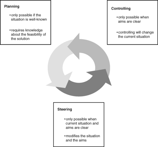
Conversely, it has proved detrimental to have these activities scheduled as far apart as suggested by the classic phase models. In these models, the “early” steps are directed towards planning, while the management carries out the steering function within the plan over a long period of time, and eventually executes the necessary controls at the end of the project. The large number of milestones and milestone documents have a formal control and monitoring function but give no real insight into the project.
12.5.2 The Contexts of the Management Process
The management process refers to different contexts: application domain, development domain, and technology domain. All three contexts have an effect on the development process and therefore must be taken into account by the management process (see Figure 12.12). The following subsections discuss the three contexts for our management process.
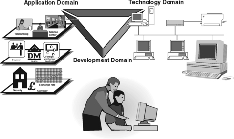
THE APPLICATION DOMAIN
The application domain is where the future software system will be used. In concrete terms, this can be an organization, an organizational unit, or a workplace type. The application domain determines largely how a project will be oriented and executed.
From the application developer’s perspective, it is desirable to keep the application domain as small as possible to reduce the complexity of the project. For example, we would not recommend building software support for an entire hospital as the application domain. The tasks and processes are so diverse and complex that they would extend beyond the scope of any project. On the other hand, the application domain has to be large enough so that its context is still comprehensible. For example, it wouldn’t make sense to reduce the application domain in a hospital project to the work of a single ward nurse, because her work can only be understood and modeled in cooperation with doctors, administrative personnel, and other nurses.
When the application orientation is chosen, we have to answer the question of who is considered a user. In addition to the “direct” users, the people who will use the application system, there are probably other people affected by the results of the application system and modified work processes, so that they too should be integrated in the process. A good example is the issue of “customers of customers” in banks. Naturally, we will want to integrate the bank’s employees and its customers, as both groups are normally the direct beneficiaries of our application system.
THE TECHNOLOGY DOMAIN
The technological environment of a project determines which architectural concepts, design guidelines, technology models, and concrete technical components for the system base can be selected and used in the development process (see Section 9.3.7). The assessment of the technology domain is a separate and ongoing task, often underestimated by the management. The issue here is which new technologies and means are necessary for implementing the system and whether new technologies should be employed for strategic and technical reasons. A rule proven in our projects says that only one fundamentally new technology should be introduced per project. We realize that it is not always easy to stick to this rule.
The reason is that technologies are no longer selected by the corporate management alone. For instance, as a result of the recent popularity of Internet and Java technologies, many application projects were experiencing major “external” pressure to use these technologies with relative disregard of project objectives. We can therefore assume that the technology domain will increasingly develop its own dynamic that influences project direction. It is important that at least the type of technology is made known as early as possible in a project since this often affects the approach taken and the modeling.
THE DEVELOPMENT DOMAIN
The development domain is the organizational context in which a project team works. This can be an in-house IT department, a contracted software house, or a vendor of prefabricated software components. We do not take into account developers of standard software products that work for an “anonymous market,” because a fundamentally different approach is followed in many of those areas.
The development domain is often given too little attention during planning. Yet the objectives of the development team members and their strategic orientation are very important. If the use of new technologies is being planned, then a provision has to be made for further courses and training of the team. However, this usually involves more than just new development tools and programming languages. What is often overlooked is that good developers are the most important resource of any IT company. The more qualified these people are, the easier it is for the IT department to handle the central task of management.
A big problem is created when project teams are simply made up of the people who just happen to be available and no clarification is provided as to the domain-related and technological profile of a project and who can match it. We deal with the special importance of domain knowledge in Sections 13.1 and 13.2.
12.6 PROJECT PLANNING CONCEPTS AND TECHNIQUES
Many books on project management and the Unified Process use an “average” project, a project that develops an application system from scratch, as their starting point. A closer look shows that these books present a general pattern for project planning and execution. We are able to differentiate this project pattern for the T&M approach. The key dimensions are runtime and project scope.
CLASSIFICATION OF PROJECTS
The following classification provides guidance on what is needed to plan different types of projects:
• Large projects: At the top end, we see new developments or the reorganization of complete application landscapes. An example would be the redesign of a complete banking system for distributed and multichannel applications. This sort of project involves a family of systems with thousands of classes that are revised over a period of several years, gradually replacing a complete existing application. The planning and organizational effort for such an undertaking will incorporate all techniques described in this chapter.
• Medium-sized projects: At the middle level, we see the implementation of new workplace applications and more substantial application components. The scope of such projects lies in the new development of more than one hundred nontrivial classes, and the time requirement is at least six months. Here trained teams may work in a more or less familiar environment. The planning required is still considerable, but due to the partially calculable risk involved and the experience of the team, the number of very complicated or “heavyweight” techniques can be reduced or only used in isolated cases.
• Small projects: At the bottom level, a minimum planning effort is required to implement individual components and small applications. The tools of eXtreme Programming in their “pure form” usually suffice. The short project runtime of a few months and the scope of less than one hundred classes justify these simpler planning techniques.
Consequently, the first (logical) planning task for every project based on T&M is calibration. This means the selection of meaningful planning and control means that match the concrete project.
DIMENSIONS OF PROJECT CALIBRATION
The key dimensions of calibration have already been mentioned.
• The scope of the project is related to its runtime and the size of the team. The longer a project runs and the more people needed to participate, the more complicated is the planning.
• The scope and complexity of the product: the more design and construction units the system being developed comprise and the more nebulous the domain-related and technological requirements are, the more extensive is the planning.
The following can serve as modifiers of the dimensions just listed:
• Strategic importance of a project: The more strategic importance a project gains, the less management can deviate from specified objectives or identify trade-offs for the performance characteristics of the application system. The planning effort should be increased accordingly.
• Team experience: The more experienced a team is in the area of application development in general and in the existing domain in particular, the better it can assess and organize a project. Explicit planning techniques can then be used on a reduced basis.
• Stable application context: The more precisely an application domain can be modeled and the more stable the application context of the future system is, the less the deviation between the actual and projected state in the respective iteration cycles. This can also produce a noticeable reduction in the amount of planning required.
The difference in the amount of planning required is reflected in the precision of the planning numbers and the scope and quality of the pure planning documents. This has little effect on the quality of the application system.
12.6.2 Project Goals
It is fundamental that the management of a development process elaborates the aims for a project. As a vision of the future system, the project goal is the driving factor in the project. It will change during the course of the development project but must be outlined at the beginning so that the participating groups have the proper common orientation.
FORMULATING GOALS
The main questions that must be dealt with when goals are formulated are:
• What is the meaning and purpose of the software project? In other words, which corporate objectives will benefit from the development project?
• What goals are to be achieved in the application domain? Do they have to be achieved all at once, or can steps towards achieving them be identified?
• Which information technology tools are suitable to meet the goal and to what degree? Which alternatives (e.g., which organizational measures or available standard systems) are conceivable?
• Who determines when the goals have been achieved? Is it one person or interest group or several?
• What kind of time frame is required to achieve the goals? How flexible is this time frame?
Based on the specified set of goals, we plan the development project using plans for the different stages, iteration plans, and base lines starting timewise from “back to front,” that is, from the time targeted for project completion back to the time the project began. The basic idea is to work out the steps necessary to reach a subgoal.
EXAMPLE
At the beginning of a bank project, we were able to identify the following aspects for the general aims:
• The corporate customer business of the bank was to be restructured in such a way that a profit of $1 million would be produced per year in this line of business.
• As part of the restructuring of the corporate customer business, the core processes were to be supported by an interactive workplace system. The planning and design of this workplace system was to be handled initially by the in-house IT department. If necessary, suitable software available on the market would be bought as an alternative.
• The board and the department management wanted to use reviews to determine whether their objective was achieved and what contribution the software system made towards it. In addition, the management of the central development department was to check the technical quality of the software system.
• In terms of the timetable, the plan was to complete the restructuring of all business in this area, along with new IT support in all branches, within two to three years.
The subgoals were broken down as follows after discussion with application management:
• In domain terms priority was given to restructuring the loan business.
• Within the loan business balance sheet analysis was seen as the area that could profit most from IT support.
• The developer team received instructions to design a workplace for corporate customer advisors that initially would cover balance sheet analysis.
• The time frame for the first pilot system was specified as one year.
12.6.3 Decision Principles
Along with a shared vision of goals, a common repertoire of principles governing decision-making is helpful in the planning and execution of the individual steps. Such principles can affect risk handling, the form of cooperation in teams and with outsiders, and the technical aspects of the implementation.
DISCUSSION
A team that works and makes decisions on the basis of shared principles is more flexible in delegating tasks. Observance of these principles ensures that the results follow a uniform view and structure.
While clearly defined project goals provide an orientation of the meaning and purpose of a software project, well-defined principles ensure that a uniform picture is created of the approach taken and joint actions. Typical principles at the overall project level include:
Although these principles are open to interpretation and thus are not solid conditions, they provide the scope of decision-making for a project. They can often be derived from IT or corporate strategy.
Other principles consider the special situation of a project in the context of political forces and technological requirements. Examples include:
• “Risks first”: Complete the riskiest tasks and evaluate the biggest technical issues first (as recommended by the UP).
• “Water principle”: Avoid confrontations with suppliers and plan defensively to avoid obstacles on the path.
• “Look ahead but do not rush ahead”: Concentrate on essential requirements. Do not implement project parts until concrete requirements exist and are needed.
Guiding metaphors and design metaphors (see Chapter 3) that also highlight a common view for project planning are supportive for the definition of goals and principles.
12.6.4 Project Establishment
Each new project starts with an initial meeting. How well a team will be able to work together is often already determined at this meeting. Establishing and initializing a project explicitly makes it clear that the right start is important for how the project proceeds.
DISCUSSION
The start of a project has a particular impact on its success. If all the participants are given the impression that they are taking part in a viable project with clear objectives and that the project will be jointly executed by a team, chances are high that it will be completed successfully in the timeframe planned.
A project is explicitly “established” so that a high level of motivation can be achieved by the participants. The fundamental principles governing the project are clarified while the project is being established. The project establishment is often initiated in a kick-off meeting, where the project goal is defined or explained in detail. Existing deadlines are clarified, the infrastructure is fixed, and some initial rough planning takes place.
It is a good idea to clarify cooperation rules and discuss the project culture. The project culture includes informal things like dress codes when dealing with customers and users, project dinners, and dealing with deadlines. The actual project content plays no role in this; only the project goal can hint at the content.
Along with the planning activities, project establishment involves defining the level of cooperation that exists between project members. To motivate team spirit in a group, DeMarco and Lister proposes arranging joint activities such as excursions and dinners.
12.7 STRUCTURING A PROJECT BY SYSTEM DECOMPOSITION
As part of the process of defining the goals for a project, clarification is needed about which part of the system should be realized by the project. It is rarely advisable to implement an entire application system with all its envisaged functions in one project. Instead, the target system is divided into subsystems that are realized in a step-by-step process. We present the concept of a core system with extension levels and specialpurpose systems.
12.7.1 Core System and Special-Purpose Systems
The evolutionary development of application systems does not only mean that software is implemented in close author-critic cycles. With large application systems it is just as important that a complete system be developed in manageable units. The concept of a core system and special-purpose systems provides an initial guideline for the domain segmentation of large and complex application software.
THE CORE SYSTEM
An open core system can be defined once general objectives and subgoals have been finalized. The core system should be coordinated with representatives of the departments concerned. This agreement on a core system is an important factor in the success of complex development projects.
SPECIAL-PURPOSE SYSTEMS
A core system can be enhanced with special-purpose systems.
Alternatively, special-purpose systems can be developed by other manufacturers or can be bought as off-the-shelf components. The time sequence for introducing the different special-purpose systems is determined by the users. Consequently, application orientation is an important aspect of project planning for these systems.
DISCUSSION
The basis for specifying a core system and optional special-purpose systems is a common understanding of the key tasks and division of labor in the application domain. Decomposing the target system into different components can take place while the project is being established. It can also be entrusted to a higher-level committee that allocates subtasks to the individual projects. It has proven useful in new projects to partition the overall system into the core system, special-purpose systems, and the extension levels within the context of a “pilot project.” In addition to decomposing the system in as short a time frame as possible, the “core” team also builds a presentation prototype. This prototype serves as the design outline for the actual project work.
The specification of the core system and the special-purpose systems is therefore a task that is outlined but cannot be completed in its entirety at the beginning of a project.
EXAMPLE
The core system in a hospital project essentially consisted of patient administration and billing, the corresponding design of workplaces at the wards in the medical and nursing areas, as well as basic services for ward communication with different service suppliers, such as radiology, laboratory systems, and kitchens (see Figure 12.13).
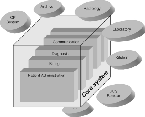
Providing these basic services as separate components for the cooperation between wards and function areas could ensure that the cooperation and coordination between ward workplaces were uniformly designed. Since new legal rulings require a strong link between administrative and medical data, we saw the need to integrate patient administration and billing with the clinical areas in the core system.
Due to the large number of requirements from the different departments and areas, we found that there was a need for a core system enhanced by several special-purpose systems. The introduction of the core system contributed greatly to involving all participants. They agreed on shared project goals and the different extension levels. This provided a good basis for the planning and execution of the hospital project.
12.7.2 Core System and Extension Levels
The close connection between different departments and tasks usually makes a core system very complex. As a result, consideration is given to decomposing the system further, and, consequently, to the domain-motivated sequences for the development and planning process. We therefore divide complex application systems into a core system and extension levels.
MINIMAL CORE SYSTEM
When a core system cannot be realized “in one piece” due to its domain or technical complexity, then we have to divide it into extension levels. First we will define a minimal core system.
The following questions are helpful in specifying a minimal core system:
• Which task in the application domain has the greatest significance?
• Which task can be supported by a limited number of tools, materials, and automatons with minimal technical complexity?
• Which software support will bring the greatest benefit for the users?
A minimal core system also often has strategic importance, because it usually is the first real object-oriented application system, at least within the context of this approach. The benefits of a “quick win” should therefore be exploited. With a minimum of effort it is possible to demonstrate a major advantage through the introduction of a minimal system in the application domain. At the same time, the special character of the T&M approach should become clear through some well-designed tools with matching materials. Of course, the basic idea can easily be transferred to pure Web applications.
EXAMPLE
In one of our projects, sections of a bank’s loan department were to be restructured. We developed an object-oriented workplace system, which was the first of its kind in this bank application. Initially, there were many reservations about the project, particularly in the IT department. In search of a suitable minimal core system, we realized that the mainframe interfaces would soon not be sufficient for interactively processing loans. In talks with the loan department, we found that many loans were being paid out on the basis of handwritten forms. So we built a small electronic payment system with resubmission and copying functions. Although the tool did not offer any specific functionality for dealing with loans, it elegantly supported some of the tedious work in the loan department. The users were greatly in favor of similar support for the other segments of the loan-processing workplace.
EXTENSION LEVELS
Once we complete our minimal core system, we have to analyze how the services designed for the entire core system are logically based on one another. To this end, we have to group these services and arrange them in successive extension levels of the core system.
First, let’s look at the definition:
Analyzing the logical dependencies between the components within extension levels, we can identify the domain-related sequence in which we can build the components of the system. Then we have to check if this sequence is feasible technically. Once we finalize the planning of extension levels, we can define the users and their tasks to be supported by the extension levels. At the same time, we have a schedule for providing the technical infrastructure of the application.
DISCUSSION
It is important for the concept of the core system and extension levels that we decompose the system according to a domain view, which is comprehensible to users. This integrates users and technical departments into the planning process.
A careful definition of the minimal core system with its extension levels provides developers and users with more clarity in recognizing and planning the consequences of iterative system development and deployment with the resulting intermediate organizational forms. At the same time, the extension levels support the task of planning accurate time horizons for a project and assessing the effort involved.
Ideally, extension levels are selected so that they can be deployed as executable versions or components, before the entire system is completed. At the very least, one extension level should always be realized as a verifiable prototype.
EXAMPLE
The decomposition into extension levels is obvious in domains with a traditional separation of different businesses (such as banks with active and passive business, securities trading, tellers, etc.). Figure 12.14 shows that this type of system partitioning can also be extended to domains with a totally different structure. The core system shown here was planned for the process automation software of a hot rolling-mill in five stages. The software components of the core system (level 0) are needed for the components being constructed in extension level 1, for example, the “primary data handler” is based on the “telegram handler.” The component for model computation being developed in extension level 4 cannot be developed without the components of extension level 3 (reading value processing, model control, and material tracking).
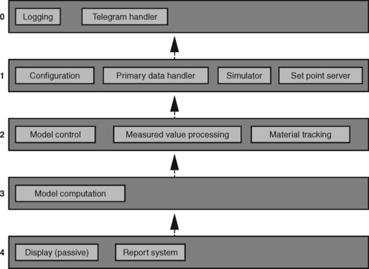
12.8 SCHEDULING AND TASK PLANNING
We have a list of the techniques and approaches for scheduling and task planning recommended for different types of projects and systems:
• On the basis of set goals and a partitioning of the system into a core system and extension levels, we recommend a process model and a time estimation for each of the system components or extension levels being developed. For the planning approach, we suggest a division into project stages and base lines.
• For very large systems or systems that are partitioned differently, we integrate project stages and base lines with the general concept of cycles and iterations of the Unified Process.
• At the micro level of large projects or for small and very flexible projects, we propose the planning instruments of eXtreme Programming.
12.8.1 General Rules for Time Estimates
An overall time estimate has to be presented for large projects. For large and complex projects, this time estimate can only be very rough and only provide an indication of what is feasible in terms of time. However, the estimate can refer to figures from previous experience or general criteria.
DISCUSSION
An initial time estimate involves sketching the time frame in which the components of an application systems could possibly be realized. A discussion of the different imponderabilities in an application-oriented software project, such as those discussed in this book, should make one thing clear: It is not possible to present an accurate overall time plan of a large project. However, “rules of thumb” based on figures from past experience can be used for a rough estimate:
• Each prototype development cycle takes between one and three months. The question, therefore, is how many prototype versions should be and can be developed.
• When using XP techniques, we calculate between three and six months for a release cycle with a delivered system version.
• Interviews and scenarios form an essential basis for every development project. Approximately one day should be planned for the interview team per interview, including the time needed for evaluation. Scenarios have to be written, read by the interview partners, and then jointly discussed. A scenario with an experienced interview team takes about one work week. Therefore, we have to estimate the number of interview teams required to produce scenarios, how many interviews and interview partners we will need, and to what extent the work can be carried out in parallel.
• The time needed for the design and construction of a workplace system can be estimated largely on the basis of tools, materials, and domain values. For example, for trained developers building software along the lines of the T&M approach based on a validated domain model, we calculate half a pair-day per average domain value, one to three pair-days per material, and two to five pair-days per typical T&M tool.
• Similar experience also exists for domain1 service providers and the connection to ERP systems. We calculate two to three pair-days for a domain service provider of average complexity, and one to two pair-days for database mapping. In our experience, host developers, who are usually relatively good at this, are the best at calculating the additional time needed for adjustments on the host system side.
• The organizational installation and field test of the pilot system also need a certain period of time that cannot easily be reduced. One should count on one to three months here.
These simple rules of thumb (modified through the reader’s own project experience) can be used to estimate whether the time expectations of management or the user organization are at all realistic. The time estimate obviously becomes less accurate
• when there is little familiarity with the respective application domain.
• when there is little familiarity with the type of application system being developed and the methodology and technology used.
• the more system components and extension levels are incorporated into the estimate.
This form of time estimation should not be confused with the normal scheduling in a project. It serves as a kind of feasibility test to determine whether a project can be carried out at all in the desired form.
12.8.2 Planning the Project Stages
If an application system has been suitably partitioned and a rough schedule planned, then the actual project planning is carried out on the basis of project stages. These stages define manageable project segments. They also link constructive quality assurance with an application-oriented approach.
PROJECT STAGES
In the Sections 12.7.1 and 12.7.2 on the core system and its extension levels, we stressed the importance of decomposing a complex application system into manageable design and construction units. If such a unit is defined as a core system or an extension level, the development process has to be planned in more detail.
We execute projects on a goal-oriented basis. When a goal for a project exists, we can decide which means, or which application system components, will contribute towards achieving this goal. It makes sense to define manageable subgoals and to work through them in a project stage.
DISCUSSION
The completion date for a system under development is usually based on a rough time estimate for the project and management’s own ideas on the subject. The basic idea of planning based on project stages involves starting from the projected completion date of a project and working backwards according to the different stages.
Using the goal as a starting point, we define the project stages working in the reverse. The idea of project stages is comparable to the Unified Process. In so far as operative versions are being developed, these in turn are usually realized in substeps as the core system or the extension level of an application system, and these substeps are revealed to all participants. The same applies when building “only” a prototype. A project stage therefore produces a result visible to all participants, and at the same time, it serves as a control instrument for further planning.
Each project stage is concluded with an event, where a prototype or the system version is presented and evaluated. On this basis, the participants decide whether the respective project stage goal has been achieved. It should be noted that different kinds of prototypes are used in the respective stages, depending on the questions being dealt with.
There is another important difference from traditional management techniques: All documents generated to that point are checked for the current project planning. It is therefore common that feedback on a user interface prototype will clarify for users and developers whether the domain analysis with scenarios was sufficient or requires further detail. System visions are also repeatedly examined for their feasibility.
This examination can be a formal review with users or a simple presentation given to a project committee. The important point is that key groups and decision-makers are informed of the project’s progress and made aware of possible problems.
At the conclusion of each project stage, the project plan is revised in terms of content and schedule. Various aspects are taken into consideration:
• Has the goal set for the project stage been achieved? If not, is it still basically achievable?
• What is the significance of the result of the project stage for the next stage? If the result was worse than expected, what effect will it have on the next project stage? Are modifications needed to the distribution of work, or is there a risk of not meeting the next stage’s goal?
• What are the chances of still achieving subgoals or the overall goal with reduced means (i.e., system features) if the result for a project stage is unsatisfactory?
If revisions to the plan are necessary due to the evaluated results of a project stage, we again focus on the overall goal. Project teams should stick to this goal to the extent possible, and when problems and timing bottlenecks occur, consider whether the goal can be achieved using fewer or other resources. We have always had the same experience in projects: From the view of the users, a “thinner” application system with less features than the ones originally planned, or a reduced extension level, can well be an accepted and almost equally welcome solution to their current problems. A reduced system version delivered on time is preferable to a long delay in almost all cases.
Project stages should normally extend over a period of between six weeks and three months. A large number of short stages is not easy to manage and creates a hectic situation. On the other hand, planning is difficult if the intervals are long, and they also create problems for the author-critic cycles.
In practice, it has proven useful to have the team discuss the planning of project stages. In projects with small teams, such plans can also be worked out jointly. With large project teams, the plan can be prepared and then discussed in a project meeting, revised if necessary, and adopted. In view of the application orientation we want to achieve, users should also have an influence on the plan. All deadlines that affect users should at least be agreed upon with them.
EXAMPLE
Figure 12.15 refers to the example of setting goals (see Section 12.6.2) and shows how these goals can be implemented. This includes the definition of a minimal core system, which is now planned with the help of project stages. Our approach of organizing this plan from back to front is again important here. In this example, the completion date for the core system was set for 02-15-2002. All other deadlines are calculated from this date backwards.
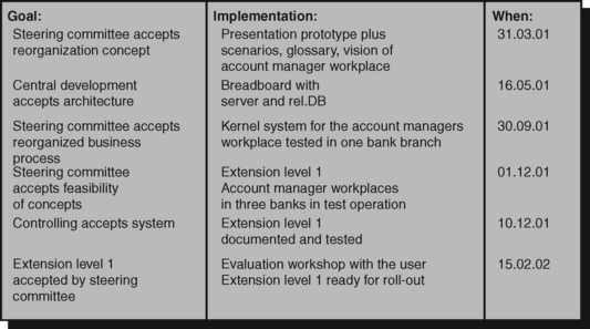
BACKGROUND: PROJECT STAGE PLANS AND CONFERENCE PLANNING
Why do we plan stages from back to front? There is a simple reason: We often find that some conventionally planned software projects exceed their time budget by far. In contrast, we have observed that most conferences actually take place exactly when and where they have been planned long before the actual events. Conferences can obviously be planned according to a precise date.
What is the big difference between conventional project planning and conference planning? We think that this difference has little to do with the fact that conferences are not software systems. Conferences are simply planned differently, namely, from back to front. Once a program committee has agreed on the location and date for a conference, then certain intermediate results or stages are tied to certain dates. For instance, if the conference proceedings are to be distributed among the participants, they have to be available in printed form at the organizers’ two to three days beforehand.
This means that the print masters have to be at the printer, for instance, one month before that date. This date, in turn, determines when the conference proceedings have to be edited for content, and so on. This is how program committee meetings, deadlines for completed papers, and the dispatch of call for papers are planned and scheduled. Any planning deviations are always noticed very quickly while a conference is being prepared. Organizers can then take suitable actions to ensure that the conference is not jeopardized. For example, lectures are deleted from the conference program or other speakers are invited on short notice when illness or another unforeseen circumstance prevents a scheduled speaker from participating.
On the other hand, we could argue that when we organize conferences we have a much more accurate idea of the steps and results required and how they depend on one another. However, our experience has shown that there is nothing against using these fundamental planning principles in software projects.
12.8.3 Using Base Lines for Detailed Planning
Planning according to project stages is still so rough that it is difficult to identify any work packages or responsibilities from it. Base lines are therefore used for fine planning within a project stage.
BASE LINES
Planning based on project stages provides no information about the distribution of tasks and responsibilities. In our experience, this type of finely granular planning usually becomes necessary and reasonable at the level of the current project stage. This is where we use base lines.
DISCUSSION
A base line primarily describes the quality expected of the next document or program. Ideally, documents and programs should be edited until the desired (and checkable) state is achieved. The same applies when events are specified in base lines. It is important that a base line identifies who will be responsible for ensuring that it is achieved. Though this person is responsible, he or she doesn’t have to do the work on his or her own.
In the sense of our general approach, base lines define tasks. They bundle domain-related and goal-oriented activities relating to a document or system component. The respective tasks should be small enough that they can be completed by a minimum number of people within a manageable amount of time. This also results in an apparent contradiction: We said that base lines should only be oriented to quality characteristics and not to time. At the same time, we demand that time and work estimates should be linked through base lines. When base lines are distributed in a team, the team members responsible for a base line gradually develop a very good feeling about how long they will need to work on it.
Base lines should be discussed jointly in a team. The size of the team and the complexity of the project determine whether the base lines are also worked out by that team. In any case, certain means of representation are available. We have had good experience with wall pictures where base lines and personnel resources are displayed in tabular form. Depending on how they are arranged, these wall pictures show the logical connections between base lines and facilitate planning and discussion of the project scheduling (see Table 12.1 and Figure 12.16).
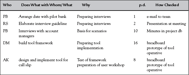
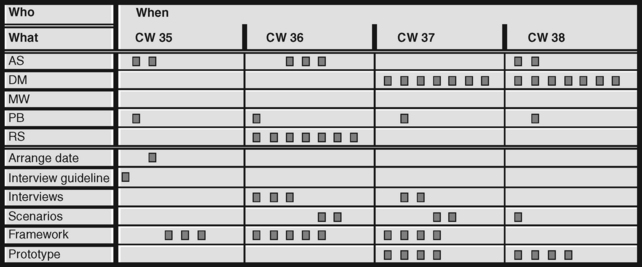
We can report from experience that the planning procedures described here have also been effective for projects with very critical application and technology domains. The cyclic approach and orientation to executable prototypes and system versions for project stages are obviously the key factors that make this procedure successful. The cyclic approach also helps projects dealing with imponderabilities. The concrete and presentable intermediate results motivate the team and demonstrate to “outsiders” that a project is progressing.
Base lines should be viewed as an alternative to the story cards of XP. They are perhaps somewhat more “conventional” than story cards and therefore easier to use in areas where the principles of eXtreme Programming cannot be applied.
Base lines are also used in the Unified Process. Here they are interpreted in a much more conventional way, because they are “frozen” at a certain point, and an explicit procedure is needed to change them again.
EXAMPLE
Let’s take another look at our previous example of a bank’s workplace system for corporate customer advisors. The base lines in Table 12.1 are listed as a kind of purpose table (see Section 13.8).
The list always includes the names of the people responsible (using abbreviations), the base line, the purpose, the person-day estimates, and the type of checking used for the base line. The form of presentation is not what is important here; it should only indicate what has to be taken into account when the base line is worked out. We can see that base lines can be planned very precisely, involving from one to a few person-days in this example. Of course, this type of finely granular planning is only recommended for projects with tight deadlines and a high degree of uncertainty. On the other hand, experience has shown that it is not a good idea to have large work packages, because it makes estimating them more difficult, and there is not enough feedback to control the planning.
To carry our example a step further, Figure 12.16 uses the base lines of Table 12.1 as the foundation for detailed scheduling. The calendar overview, in this case divided into weeks, shows the initials of each team member. The boxes are used to fill in “absences” from the project: days off for vacation, committee meetings, or other reasons. This part of the overview is usually generated early on in a planning meeting and often shows in a sobering way the personnel resources available.
The individual base lines are then entered in the bottom part of the calendar, which shows when these base lines have to be handled. For the sake of keeping things simple, we left out cross-references between the bottom and top parts in Figure 12.16.
12.8.4 The UP and T&M Project Planning
So far, our project planning has been motivated primarily from the standpoint of system partitioning into core system and extension levels. However, this planning instrument can also be integrated into the general Unified Process approach. This means that this technique is also appropriate for very large projects or systems that are partitioned in a totally different way.
UP EVOLUTIONARY CYCLES
At its highest level, the development process using the Unified Process allows a random number of evolutionary cycles that an entire system will pass through during its lifetime.
A totally new system is developed in the first cycle, similarly to conventional development projects. The development of this system is continued in an evolutionary way over its entire life cycle. Our approach organizes this continued development in projects, that is, in the sense of UP, we talk about evolutionary cycles (see Figure 12.17).
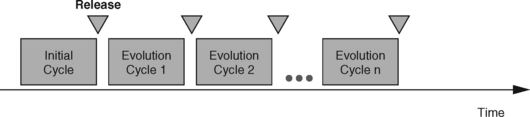
Evolutionary cycles based on UP normally consist of four phases1 that can be mapped to our concept of project stage.
Looking across projects, each stage according to T&M has concrete goals and particular topics: conceptualization, design, construction, and transition. We see them as subordinate topics rather than steps like those in a waterfall model. Thus the topic “design” is produced through activities that analyze, model, and construct things within a stage. The following section discusses these topics.
DISCUSSION
This section interprets parts of the Unified Process from the view of the T&M approach. We give priority to a cyclic and iterative approach in projects. Other authors see this differently. For example, the literature often recommends defining the number of cycles and work steps precisely, which means that these authors encourage classic life cycle models.
Note that this section is not geared to “normal” development projects. Instead, we examine the long-term evolutionary process of developing a large system, or better, a family of applications in the course of several projects. An evolutionary cycle corresponds to the development of a system version, or major system part. Each individual project that contributes to the new version can be oriented towards general issues: conceptualization, design, construction, and transition (see Figure 12.18). The results of these subprojects are merged to create a complete system family at the end of the evolutionary cycle. The goal of creating a uniform system family can only succeed independently of organizational circumstances under the following conditions: if project members keep sight of the common basis of the subprojects and have a clear understanding of the fact that they all contribute to an existing whole.
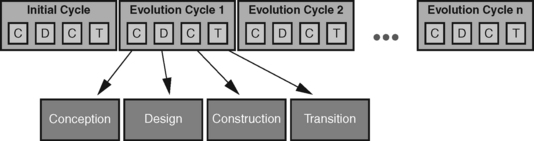
THE UP PHASES
At the next level a T&M project is organized in stages. This is our interpretation of what is called phases in the UP. Each stage within an evolutionary cycle has its own goals. It is organized as a separate project. This means independent and consistent planning. It is important that each of these subprojects includes all activities of a software project, or the construction and evaluation work. This is in clear contrast to the steps in the classic waterfall model.
A concrete stage has project-specific goals that cannot be described in general terms. However, general issues or themes are abstracted to these goals. We explain these general characteristics of the individual stages below. The document types and tasks relevant for project stages will be described in more detail in Chapter 13.
The conceptual stage describes relevant business use cases (actual state), identifies initial visions for the future system, and builds the first prototypes. These will initially be presentation prototypes. If possible, however, they should be extended to include functional and technical aspects in the form of a T-prototype (see Section 13.6). A rough range of system features and the technical basis for the project should be finalized by the end of the conceptual stage. In addition, a description of the key (critical) functions should be available. Cooperation pictures should be used to clarify the planned cooperation model. The results of the conceptual stage set the foundation for more accurate planning in the design stage.
Planning during the design stage is mainly based on the range of features defined in the conceptual project stage. Further system visions and other documents of the target model are specified during this stage, until the desired range of features is covered, and the project is ready for evaluation. The system visions are converted into domain and technical design models and realized through prototypes. At the same time, domain and software issues are further clarified. This stage focuses on providing fully operational prototypes and on specifying a logical architecture for the target system. We then use the results of this stage to confirm what we said in the beginning of this section, that this kind of decomposition into project stages is useful for large development projects only, because its high cost would not be justified in small projects.
The construction stage uses unit tests to check the prototype resulting from the earlier stages to assure its quality. This is the last stage where things like the assertions of the contracts can be checked for completeness.
By now, the developing system should have matured so that certain questions regarding performance or embedding into the context of the system can be answered. Constant feedback, above all on the functional prototypes and pilot systems (see Section 13.6), helps to make sure that the scope of system features corresponds to the actual needs and ideas of the group involved.
If possible, the organizational implementation of the system should include the use of pilot systems. Experience has shown that domain inconsistencies and implementation errors can often be identified in this stage. These errors usually result from the special system configuration on site and are particularly unpleasant. The end of this stage completes the entire cycle of the four stages described in this section.
PROJECT STAGE PLANS
A project stage plan contains the concrete planning for a cycle. It is directed towards the concrete subgoals of a project. In general, the project stage plan should identify the specifc topics relating to the four general stages of conceptualization, design, construction, and transition.
Along with the goals for the different stages, the project stage plan contains the profiles of the project members and information about the resources required over the course of the entire cycle. Figure 12.19 shows that resources are distributed in different ways. In addition, the project stage plan contains rough details about the duration of the iterations and the subtasks already associated with them. The project stage plan is created early in the conceptual stage and edited as often as necessary. It shouldn’t be more than two to three pages long.
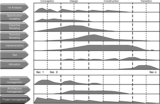
Obviously, the length of the individual stages is not the same in each project. The starting point for a project stage plan is a typical project profile with, for example, the following characteristics:
• The project is of a moderate size and its cost is justified.
• The project is in the initial cycle.
• The project does not have a predefined architecture.
• The project has a limited number of risks and unknown factors.
This basic project profile can be adapted to a specific project, based on the following rules:
• If the actual tasks are still not clarified at project start, that is, the requirements are not clear, then the conceptual stage may have to be extended.
• If an appropriate architecture cannot be found because some things are still unclear regarding system design, cooperative work is being supported, or a group of new employees is to be integrated, then the design stage has to be extended.
• If new technologies are to be used, a distributed system is performance-critical, a high level of parallel system access is expected, or a large number of technical problems exist, then the construction stage should be broken up to address each problem specifically.
• If the second generation of an existing product is involved (a new evolutionary cycle) and no far-reaching modifications are required, then the conceptual and design stages can be shortened.
• If a product has to be available on the market quickly, either because the development is seriously behind schedule or the customer wants to reshape the market, and the product has been announced for a specific shipping date, then the construction stage can be shortened and the transition stage extended.
• If the project involves a complicated installation, for example, replacing an old system with no downtime allowed, or if the acceptance procedures are particularly complex, then the transition stage has to be extended.
DISCUSSION
This section generalizes the concept of project stages and maps it to the general process model of the Unified Process. Section 12.8.2 defined project stages as being goal-oriented and producing an executable system vision or a prototype as the result. Stages are therefore very suitable as planning units in projects where the system is divided into a core system and extension levels. However, this type of partition becomes superfluous when a large system with the expectancy of a long span is reengineered (or refactored) on an evolutionary basis. In this case, the system already exists with a full range of features.
In this section we therefore orient the project stages towards more general topics. Each stage is planned as a separate project and implemented with all meaningful activities. Therefore each stage has a project-specific objective. The four topics, of conceptualization, design, construction, and transition should make clear that the results of the stages can always be directed toward different general issues. This does not mean that each stage only produces one concept, works out one design, constructs one program, or ships one product. This obvious deviation from the principles of the classic waterfall model is common to both the Unified Process and the T&M approach. We are pleased to see that an evolutionary and iterative approach is gradually catching on.
ITERATIONS
Each of the stages discussed can be divided into several iterations. All necessary tasks are executed within each iteration in order to promote the maturing process of the development documents and the code.
An iteration can be interpreted as a complete miniproject, where all key development tasks are executed. The result of an iteration is an executable system version, usually a prototype, and a number of documents. An iteration therefore starts with a planning and requirements analysis and ends with an internal integration or an external release. We use the base lines of the T&M approach to identify the documents and prototypes generated in each iteration, their purposes, and the people in charge of their validation.
DISCUSSION
An iteration represents the finest granularity of incremental software development that can be planned. The scope of an iteration depends heavily on the project calibration. It only pays to embed true miniprojects with their own planning horizons within a stage if project families are arranged at the top end of the scale, that is, if they are to run for several years.
The sensible length of a full-blown and planned iteration within a stage is one to three months. We assume that a development process based on the principles of eXtreme Programming (see Sections 12.3.4 and 12.3.5) should be selected for an iteration duration of less than one month.
The iterations of medium-sized projects with an iteration duration of less than one month are reduced to the scale of what is referred to as short releases in eXtreme Programming and supported by planning games (see subsequent Section headed “Using XP for Detailed Iteration Planning”). Small projects of short duration can completely dispense with iterations within a stage since the entire stage can be planned and controlled at the planning games level.
Development activities are carried out with varying degrees of intensity, depending on the stage, number of iterations, and problems. Though there can be different focal points, all tasks pass at least one iteration (see Figure 12.20). As a consequence, all document types and models are basically at hand for processing. Each document or model is then handled with the intensity defined by logical and individual priorities.
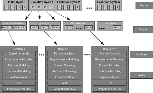
Regarding content, each iteration is driven by selected visions or use cases selected from the range defined for the system. After each iteration, a set of base lines is checked to enable the detailed planning of the next iteration.
ITERATION PLANNING
The individual iterations are planned with the described base lines (see Section 12.8.3). Normally two iteration plans are important in a project in parallel:
USING XP FOR DETAILED ITERATION PLANNING
We use the from eXtreme Programming to make work orders easier to manage and to establish new requirements. Story cards are file cards used to document the requirements from the users’ view, similar to use cases in UML. In XP, customers and users write the story cards themselves, which can create problems. We think that this method doesn’t work well, unless both the customers and users are familiar with the requirements. Moreover, they are often not able to evaluate the technological options available. Therefore, developers using the T&M approach normally write the story cards based on their understanding gained from customer and user interviews. The story cards are then given to customers and users for comments.
Developers working in pairs (see “Pair Programming” in Section 12.3.4) often find that some parts of the system require refactoring. If this need for refactoring is extensive, then the developers can write their ideas on. Engineering cards are like story cards, except that they refer to technical aspects. In addition, are often used; they are similar to story cards, but go beyond a specific story. Tasks that are useful for several stories can therefore be extracted from them.
Developers use these cards to plan individual iterations by sorting the cards based on usefulness and urgency in cooperation with the customer. Each card describes certain tasks and can be used to check a base line. The achievement of a base line is controlled on the basis of the cards assigned to this base line. For small to medium-sized projects, the story and engineering cards can simply be used as a substitute for explicitly formulated base lines. The cards are then directly allocated to the project stages.
Although story cards can be used for small projects, they are also a good means for coordinating several application projects with the development of a framework used. Story cards are excellent planning and control mechanisms for small projects, where the full set of system versions, core systems with extension levels, project stage planning, iteration plans, and base lines would be too extensive. Requirements are documented on the story cards and ranking by the customer according to usefulness and urgency. The developers take the story cards to identify the construction tasks to be handled, if necessary write task cards, and plan the individual tasks. These are then processed in a way that allows the tasks to be checked. The story card method follows a basic idea of the Unified Process to “define requirements when they become visible,” while the “risk-first” principle applies to task planning. Finally, the set of defined requirements is used to check whether they have been met. The Unified Process offers use cases rather than story cards for this purpose.
Story cards are also used when several application projects work parallel to the further development of a framework. The framework developers use story cards to write down new ideas or document the requirements of the framework users (namely, the application developers). In regular architectural meetings, the product manager and framework users sort these story cards according to urgency, discuss individual problems and solution approaches, and distribute the work among the framework developers.
This ensures that the requirements of the application developers are documented and the requirements from the individual projects are compiled and examined in an overall context.
12.9 DISCUSSING T&M, UNIFIED
PROCESS, AND XP
The evolutionary approach of T&M can be seen as an application-oriented interpretation of the Unified Process. At the same time, we integrate the techniques and presentation means of eXtreme Programming. The basic principles of UP coincide with the ideas of XP and T&M. A shift in emphasis occurs when it comes to the question of complexity and type of documentation and the size of the respective planning units.
12.9.1 Structure of the UP and T&M Development Processes
UP and T&M are similar in the size of planning units. A development project based on UP is divided into cycles, phases, and iterations. We know from Section 12.8.4 that the system versions and extension levels of a family of application systems can be developed in the cycles defined in UP. While UP looks at external and internal releases including increments, the T&M approach shapes core systems, special-purpose systems, and extension levels from an application-oriented view.
In UP the phases are the next planning and control level. They can be seen as the abstract units of what we call stages. In UP, phases are subdivided according to the abstract topics, which are inception, elaboration, construction, and transition. The stages in T&M are always oriented towards project-specific goals. When we look at them in abstract terms, we see general topics. With a light shift of emphasis, compared to UP, we call our stages concept, design, construction, and transition stages.
In UP, systems are developed cyclically in iterations (see Figure 12.21). We have shown that the iterations of UP can easily be divided and planned through the use of the T&M base lines.
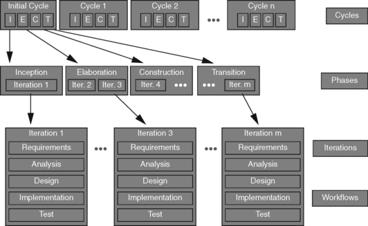
We see from Figures 12.21 and 12.22 that the UP and T&M iterations are similar, except that the T&M approach emphasizes the activities. As suggested by the workflows in UP, we first assume that all types of activities generally have to be done in parallel to complete these tasks, and then repeated in each iteration, while the priorities and actual sequence vary from one project to another. To better understand this basic idea, both figures list the activities in columns instead of a horizontal time sequence.
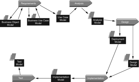
The main differences appear in the number and type of activities. A brief comparison clearly shows this:
• UP: Requirements, analysis, design, implementation, test. These activities are based on the traditional steps of the waterfall model. They are primarily seen from the view of the developer. The UP authors suggest that these activities serve as examples and can be divided up differently.
• T&M: Domain analysis, requirement modeling, domain modeling, technical modeling, implementation, testing, preparation for use. T&M focuses on both application-oriented and technical activities. At the same time, preparation for use is considered an explicit activity. A great deal of importance is attached to actual domain modeling.
DISCUSSION
At the conceptual level, the T&M process model can be easily mapped to the general UP development process. The concretization in the T&M approach is shaped by application orientation. Domain analysis, requirement modeling, domain modeling, and preparation for use are activities that explicitly include the users and run in author-critic cycles. A characteristic feature is the strong focus on domain analysis and modeling. Although this is also found as a business model in UP, it is not as important there and not as integrated in the further modeling process.
The T&M approach works on the principle of structural similarity. This means that the terms and concepts of an application domain first have to be understood on the background of day-to-day tasks in that domain. Sound understanding of the actual work situation remains important for developers, even if tasks and processes change with the introduction of a new application system. This is the best way to ensure domain knowledge throughout a project to assess potential modifications and implement them into the system design.
MODELS IN THE DEVELOPMENT PROCESS
The different models in UP are allocated to workflows according to the breakdown of the development process, as shown in Figure 12.22.
We can see the following important points from Figure 12.22:
• Although the business use case model and the business object model are both specified in the UP book, they are not given the importance that other models are awarded.
• All models are relatively closely coupled to individual activities. This is particularly obvious in the test model.
Figure 12.23 shows that the T&M approach produces a somewhat different picture. In the model of the application domain, the concept model appears explicitly with the description of the actual situation. In addition, the model of the application system is split into application-oriented and technical models. The test model is linked to almost all activities, in compliance with the quality assurance concepts discussed in Section 12.3.
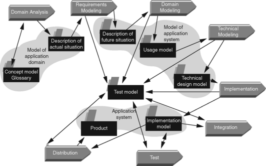
DISCUSSION
The fact that the domain models of the current situation are given so little emphasis in UP can be interpreted to mean that these models are either not important enough or are elaborated by people who are outside the actual development project. We consider both interpretations to be dangerous: As we have stated, we find it important that developers acquire a detailed understanding of an application domain. This requires explicit models. However, these models also have to be elaborated in conjunction with the users. This is the only way to encourage the learning process in the author-critic cycles.
We have already explained the importance of application-oriented models. Another thing that distinguishes the T&M approach is the notion of constructive quality assurance. This is along the same line as what the authors of UP say in their books. However, in our view it also includes the intertwining of programming and testing. Section 12.4.2 describes different test types, which are closely linked to the design and construction activities.
XP AND T&M
We have said that the techniques and representation means of XP are compatible with the T&M approach. Both approaches are characterized by strong user orientation, short development cycles, and quick releases. XP uses story, engineering, and task cards, managing simpler document types than T&M. However, if you look at T&M and XP as repertoires of methods rather than process models, then the cards and techniques (e.g., planning games) of XP represent a valuable enhancement to the T&M repertoire.
The differences between XP and T&M are found on the level of development objects. T&M distinguishes between versions and, consequently, between core system, special-purpose systems, and extension levels. Moreover, it allows for the construction of prototypes. XP is always oriented towards executable releases. At the most, it distinguishes between internal and external release, which is not something that can be seen to be of qualitative nature.
SUMMARY
Without claiming completeness, Table 12.2 lists the three approaches discussed here, comparing the key planning units and development objects. One could argue that this comparison refers to different orders of magnitude. This is true, since UP is the most extensive and also most heavyweight approach, which means that UP can also be used to plan and implement very large projects or project families involving complex documentation and development requirements.
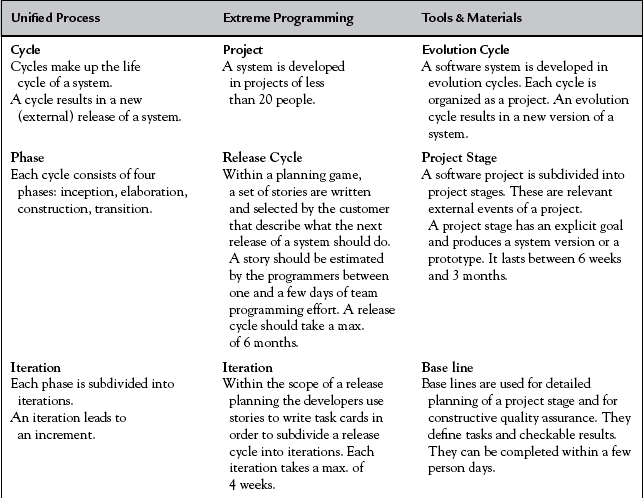
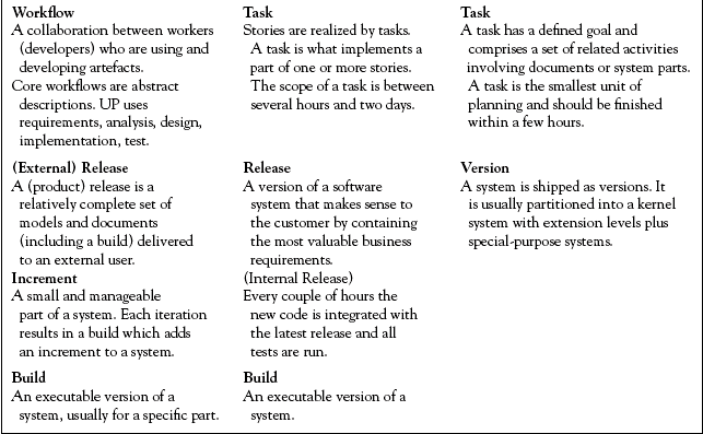
XP concentrates on smaller or lightweight projects. The development objects are also smaller, which means that larger projects first have to be partitioned. As an example of this scope, the task cards sometimes relate to very small tasks that can be completed in a few hours.
T&M (without XP integration) positions itself between the other two approaches. It is suitable for medium-sized projects and recommends the partitioning of larger projects. On the other hand, the scale of planning of base lines is usually more extensive than that of task cards in XP.
Andersen N.E., Kensing F., Lundin J., Mathiassen L., Munk-Madsen A., Rasbech M., Sørgaard P. Professional Systems Development. New York, London: Prentice-Hall; 1990. We have taken the general dimensions of a software project from this book.
Beck K. Extreme Programming Explained. Reading, Mass.: Addison-Wesley; 2000. The standard work by one of the outstanding promoters of extreme programming.
Beck K. Test Driven Development. Reading, Mass.: Addison-Wesley; 2002. This book explains the test first concept of eXtreme programming. For JUnit see http://www.junit.org
Beck K., Fowler M. Planning Extreme Programming. Reading, Mass.: Addison-Wesley; 2000. The book that is most frequently quoted for planning with XP.
Binder R.V. Testing Object-Oriented Systems: Models, Patterns, and Tools. Reading, Mass.: Addison-Wesley; 1999. A seminal work on OO testing.
Booch G. Object Solutions: Managing the Object-Oriented Project. Reading, Mass.: Addison-Wesley; 1995. More on the topic of project management in OO projects.
Boehm B. Software Engineering. IEEE Transactions on Computers. 1976;Vol. 25:1226–1241. This paper made the traditional waterfall model popular.
Boehm B. The Spiral Model of Software Development and Enhancement. Computer. 1988;Vol. 21(No. 5):61–72. Mai The seminal paper on the spiral model.
Budde R., Kautz K., Kuhlenkamp K., Züllighoven H. Prototyping. Berlin, Heidelberg: Springer-Verlag; 1992. One of our contributions to prototyping discussing traditional development strategies.
Cockburn A. Agile Software Development. Reading, Mass.: Addison-Wesley; 2001. A relevant contribution to agile methods.
DeMarco T., Lister T. Peopleware: Productive Projects and Teams. New York, N.Y.: Dorset House Publ; 1987. A standard reference for the supporting management style.
Floyd C. A Systematic Look at Prototyping. In: Budde R., Kuhlenkamp K., Mathiassen L., Züllighoven H., eds. Approaches to Prototyping. Berlin, Heidelberg: Springer-Verlag; 1984:1–18. A seminal paper which has coined the terminology and concepts of prototyping
Fowler M. Refactoring-Improving the Design of Existing Code. Reading, Mass.: Addison-Wesley; 1999. The seminal book on refactoring in eXtreme Programming.
Goldberg A., Rubin K.S. Succeeding with Objects: Decision Frameworks for Project Management. Reading, Mass.: Addison-Wesley; 1995. More on the topic of project management in oo projects.
Harel D. Statecharts: A visual formalism for computer systems. Science of Computer Programming. 1987;8/3:231–274. The seminal paper on Statecharts.
Highsmith J. Agile Software Development Ecosystems. Reading, Mass.: Addison-Wesley; 2002. A relevant contribution to agile methods.
Jacobson I. Object-Oriented Software Engineering-A Use Case Driven Approach. Reading, Mass.: Addison-Wesley; 1992. The book in which Jacobson originally introduced his use case concept.
Jacobson I., Booch G., Rumbaugh J. The Unified Software Development Process. Reading, Mass.: Addison-Wesley; 1999. Currently the standard work on procedures in projects in the context of UML.
Lehman M.M., Programs, Life Cycles, and Laws of Software Evolution. Proc. of IEEE. 1980;Vol 68:1060–1076. No. 9, Sept. Lehman explains in this paper this different types of software with respect to formalization.
Mackinnon T., Freeman S.P. Endo-Testing: Unit-Testing with Mock Objects. In: Succi G., Marchesi M., eds. Extreme Programming Examined. Reading, Masss: Addison-Wesley, 2001. This paper describes the concept of mock objects for class testing.
Parnas D.L., Clements P.A. A Rational Design-Process. How and Why to Fake It. In: Nivat M., Ehrig H., Floyd C., Thatcher J., eds. Formal Methods and Software Development, Proceedings of TAPSOFT’85. Berlin, Heidelberg: Springer, März, 1985. An important critical discussion of traditional development strategies.
Pomberger G., Blaschek G. Object-Orientation and Prototyping in Software Engineering. New York, London: Prentice-Hall; 1996. A relevant contribution to prototyping with a detailed discussion of development strategies.
Binder Robert V. Testing Object-Oriented Systems: Models, Patterns, and Tools. The Addison-Wesley Object Technology Series. 1999.
Succi G., Marchesi M. Extreme Programming Examined. Reading, Mass.: Addison-Wesley; 2001. Based on contributions submitted at the first XP conference (Italy, June 2000): This book offers an overview of conceptional and practical discussions on the topic of eXtreme Programming.
1.In UP lingo, these phases are called inception, elaboration, construction, and transition.