Light-beam alarms
In the Chapter 1 survey of modern optoelectronic devices and techniques brief mention was made of light-beam systems that can (among other things) be used as the basis of intrusion detectors and alarms. The present chapter expands on this theme by showing practical ways of making invisible IR light-beam alarms; the chapter starts off by looking at some basic principles.
Intrusion alarm basics
A simple invisible-light-beam intrusion detector or alarm system can be made by connecting an infra-red (IR) light transmitter and receiver as shown in Figure 11.1 Here, the transmitter feeds a coded signal (often a simple squarewave) into an IR LED which has its output focused (via a moulded-in lens in the LED casing) into a fairly narrow beam that is aimed at a matching IR photodetector (phototransistor or photodiode) in the remotely placed receiver. The system action is such that the receiver output is off when the light-beam reaches the receiver, but turns on and activates an external alarm, counter, or relay if the beam is interrupted by a person, animal, or object. This basic type of system can be designed to give an effective detection range of up to 30 metres when used with additional optical focusing lenses, or up to 8 metres without extra lenses.

The above system works on the pin-point line-of-sight principle and can be activated by any ‘wider-than-a-lens’ object that enters the line-of-sight between the transmitter and receiver lenses. Thus, a weakness of this simple system is that it can be false-triggered by a fly or moth (etc.) entering the beam or landing on one of the lenses. The improved dual-light-beam system of Figure 11.2 does not suffer from this defect.

The Figure 11.2 system is basically similar to that already described, but transmits the IR beam via two series-connected LEDs that are spaced about 75mm apart, and receives the beam via two parallel-connected photodetectors that are also spaced about 75mm apart. Thus, each photodetector can detect the beam from either LED, and the receiver thus activates only if BOTH beams are broken simultaneously, and this normally occurs only if a large (greater than 75mm) object is placed within the composite beam. This system is thus virtually immune to false triggering by moths, etc.
Note that, as well as giving excellent false-alarm immunity, the dual-light-beam system also gives (at any given LED drive-current value) double the effective detection range of the simple single-beam system (i.e. up to 16 metres without additional lenses), since it has twice as much effective infra-red transmitter output power and twice the receiver sensitivity.
System waveforms
Infra-red beam systems are usually used in conditions in which high levels of ambient or background IR radiation (usually generated by heat sources such as radiators, tungsten lamps, and human bodies, etc.) already exist. To enable the systems to differentiate this background radiation and give good effective detection ranges, the transmitter beams are usually frequency modulated, and the receivers are fitted with matching frequency detectors.
In most cases, the transmitted beams use either continuous-tone or tone-burst frequency modulation, as shown in Figure 11.3.

Infra-red LEDs and photodetectors are fast acting devices, and the effective range of an IR beam system is thus determined by the peak current fed into the transmitting LED, rather than by its mean LED current. Thus, if the waveforms of Figure 11.3 are used in transmitters giving peak LED currents of 100mA, both systems give the same effective operating ranges, but the Figure 11.3(a) continuous-tone transmitter consumes a mean LED current of 50mA, while the tone-burst system of Figure 11.3(b) consumes a mean current of only 1mA (but requires more complex circuit design).
The operating parameters of the tone-burst waveform system require some consideration, since the system actually works on the ‘sampling’ principle. For example, it is a fact that at normal walking speed a human takes about 200ms to pass any given point, so a practical IR light-beam burglar alarm system does not need to be turned on continuously, but only needs to be turned on for brief ‘sample’ periods at repetition periods far less than 200ms (at, say, 50ms); the sample period should be short relative to repetition time, but long relative to the period of the tone frequency. Thus, a good compromise is to use a 20kHz tone with a burst or sample period of 1ms and a repetition time of 50ms, as shown in Figure 11.3(b).
System design
The first step in designing any electronics system is that of drawing up suitable block diagrams; Figure 11.4 shows a suitable block diagram of a continuous-tone IR intrusion alarm/detector system, and Figure 11.5 shows that of a tone-burst system. Note that a number of blocks (such as the IR output stage, the tone pre-amp, and the output driver) are common to both systems.


The continuous-tone system (Figure 11.4) is very simple, with the transmitter comprising nothing more than a squarewave generator driving an IR output stage, and the receiver comprising a matching tone pre-amplifier and code waveform detector, followed by an output driver stage that activates devices such as relays and alarms, etc.
The tone-burst system is far more complex, with the transmitter comprising a free-running pulse generator (generating 1ms pulses at 50ms intervals) that drives a gated 20kHz squarewave generator, which in turn drives the IR output stage, which finally generates the tone-burst IR light-beam. In the receiver, the beam signals are picked up and passed through a matching pre-amplifier, and are then passed on to a code waveform detector/expander block, which ensures that the alarm does not activate during the ‘blank’ parts of the IR waveform. The output of the expander stage is fed to the output driver.
Figure 11.6 shows an alternative version of the tone-burst system. This is similar to the above, except that a simple code waveform detector is used in the receiver section, and that a blanking gate is interposed between the detector and the output driver and is driven directly by the transmitter’s pulse generator, to ensure that the alarm is not activated during the blank parts of the IR waveform.

Transmitter circuits
Figure 11.7 shows the practical circuit of a simple continuous-tone dual-light-beam IR transmitter. Here, a standard 555 timer IC is wired as an astable multivibrator that generates a non-symmetrical 20kHz squarewave output that drives the two IR LEDs at peak output currents of about 400mA via R4 and Q1 and the low source impedance of storage capacitor C1. The timing action of this circuit is such that the ON period of the LEDs is controlled by C2 and R2, and the OFF period by C2 and (R1 + R2), i.e. so that the LEDs are ON for only about one eighth of each cycle; the circuit thus consumes a mean current of about 50mA.
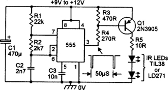
The above circuit can use either TIL38 or LD271 (or similar) high-power IR LEDs. These popular and widely available LEDs can handle mean currents up to only 100mA or so, but can handle brief repetitive peak currents several times greater than this value. Figure 11.8 shows the outline and connections of these devices, which have a moulded-in lens that focuses the output into a radiating beam of about 60° width; at the edges of this beam the IR signal strength is half of that at the centre of the beam.

Minor weaknesses of the IR output stage (Q1 and R3–R4) of the Figure 11.7 circuit are that it has a very low input impedance (about 300 ohms), that it gives an inverting action (the LEDs are ON when the input is low), and that the LED output current varies with the circuit supply voltage. Figure 11.9 shows an alternative universal IR transmitter output stage that suffers from none of these weaknesses.

In Figure 11.9, the base drive current of output transistor Q2 is derived from the collector of Q1, which has an input impedance of about 5k0 (determined mainly by the R1 value). Thus, when the input is low Q1 is off, so Q2 and the two IR LEDs are also off, but when the input is high Q1 is driven to saturation via R3, thus driving LED1 (a standard red LED) and Q2 and the two IR LEDs on.
Note that under this latter condition about 1.8V is developed across LED1, and that about 0.6V less than this (= 1.2V) is thus developed across R4. Consequently, since the R4 voltage is determined by the Q2 emitter current, and the Q2 emitter and collector currents are virtually identical, it can be seen that Q2 acts as a constant-current generator under this condition, and that the IR LED drive currents are virtually independent of variations in supply voltage. The peak LED drive current thus equals approximately 1.2/R4, and R4 (in ohms) = 1.2/I, where I is the peak LED current in amps.
Figure 11.10 shows a 20kHz squarewave generator (made from a 555 timer IC) that can be added to the Figure 11.9 output stage, to make a continuous-tone IR beam transmitter. In this case R4 (in Figure 11.9) should be given a value of at least 6.8 ohms, to limit peak LED currents to less than 200mA.

Alternatively, Figure 11.11 shows the circuit of a tone-burst generator (giving 1ms bursts of 20kHz at 50ms intervals) that can be added to Figure 11.9 to make a tone-burst transmitter. Here, two sections of a 4011B CMOS quad 2-input NAND gate IC are wired as a non-symmetrical astable multivibrator producing 1ms and 49ms periods; this waveform is buffered by a third 4011B stage and used to gate a 20kHz ‘555’ astable via D2, and the output of the 555 astable is then inverted via a fourth 4011B stage, ready for feeding to the transmitter output stage.

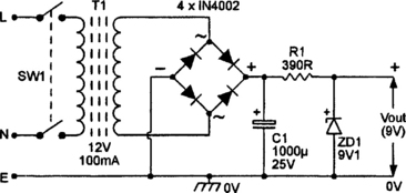
Note when using the Figure 11.11 circuit that R4 in Figure 11.9 can be given a value as low as 2.2 ohms, to give peak output currents of about 550mA, but that under this condition the transmitter consumes a mean current of little more that 6mA; this current can be provided by either a battery or a mains-derived supply; a suitable mains-powered 9V DC supply is shown in Figure 11.12.
A Receiver pre-amp
Figure 11.13 shows the practical circuit of a high-gain 20kHz tone pre-amplifier designed for use in an infra-red receiver. Here, the two IR detectors are connected in parallel and wired in series with R1, so that the detected IR signal is developed across this resistor. This signal is amplified by cascaded op-amps IC1 and IC2, which can provide a maximum signal gain of about × 17 680 (= ×83 via IC1 and ×213 via IC2), but have their gain fully variable via RV1. These two amplifier stages have their responses centred on 20kHz, with 3rd-order low-frequency roll-off provided via C4–C5–C6, and 3rd-order high-frequency roll-off provided by C3 and the internal capacitors of the ICs.

The above circuit can be used with a variety of IR detector diode types, which ideally should be housed in black (rather than clear) infra-red trans-missive mouldings, which greatly reduce ambient white-light interference. Figure 11.14 shows the case outline and IR-sensitive face positions of three popular IR photodiodes of this type.

The output of the Figure 11.13 pre-amplifier can be taken from IC2 and fed directly to a suitable code-waveform detector circuit, such as that shown in Figure 11.15. Note, however, that if the Tx–Rx light-beam system is to be used over ranges less than 2 metres or so the pre-amp output can be taken directly from IC1, and all the RV1 and IC2 circuitry can be omitted from the pre-amp design.
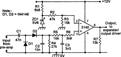
Code waveform detector
In the Figure 11.15 code waveform detector circuit the 20kHz tone waveforms (from the pre-amp output) are converted into dc via the D1–D2–C2–R5–C3 network and fed (via R6) to the non-inverting input of the 3140 op-amp voltage comparator, which has its inverting input connected to a thermally stable 1VO dc reference point. The overall circuit action is such that the op-amp output is high (at almost full positive supply rail voltage) when a 20kHz tone input signal is present, and is low (at near-zero volts) when a tone input signal is absent; if the input signal is derived from a tone-burst system, the output follows the pulse-modulation envelope of the original transmitter signal. The detector output can be made to activate a relay in the absence of a beam signal by using the expander/output driver circuit of Figure 11.16.
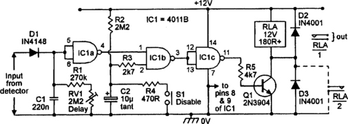
Expander/output driver
The operating theory of the Figure 11.16 circuit is fairly simple. When the input signal from the detector circuit switches high C1 charges rapidly via D1, but when the input switches low C1 discharges slowly via R1 and RV1; C1 thus provides a dc output voltage that is a ‘time-expanded’ version (with expansion pre-settable via RV1) of the dc input voltage. This dc output voltage is buffered and inverted via IC1 a and used to activate relay RLA via Q1 and an AND gate made from IC1b and IC1c.
Normally, the other (pin-2) input of this AND gate is biased high via R2, and the circuit action is such that (when used in a complete IR light-beam system) the relay is off when the beam is present, but is driven on when the beam is absent for more than 100ms or so. This action does not occur, however, when pin-2 of the AND gate is pulled low; under this condition the relay is effectively disabled.
The purpose of the R2–C2 network is to automatically disable the relay network via the AND gate (in the way described above) for several seconds after power is initially connected to the circuit or after DISABLE switch S1 is briefly operated, so that the owner or other authorized persons can safely pass through the beam without activating the relay. Note that the relay can be made self-latching, if required, by wiring normally open relay contacts RLA/2 between Q1 emitter and collector, as shown dotted in the diagram.
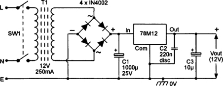
A power supply
The circuits of Figures 11.13, 11.15 and 11.16 can be directly interconnected to make a complete infra-red light-beam receiver that can respond to either continuous-tone or tone-burst signals. Such a receiver should be powered via a regulated 12V DC supply; Figure 11.17 shows the circuit of a suitable mains-powered unit.