
Chapter 8. Multicast
Most of the host-based traffic seen on IPv4 networks is the result of unicast (node-to-node) or broadcast (node-to-everyone) frames or packets. The third type of traffic is called multicast, which is used to contact a subset of the nodes on the network or to create a one-to-many transmission. Perhaps the most famous use of multicast comes to us from the MBone, the Multicast Backbone project. While interest in the MBone project is somewhat quiescent, multicast still has its uses in networks today, including video streams, protocols such as spanning tree, and vendor-specific communication. With IPv6, we also see much greater dependence on multicast as broadcast addressing is no longer used. Thus, it becomes important for a network administrator to know something of multicast operation and its impact on the network.
Multicast has two parts: that which occurs between devices on the same network and a component that enables multicast over a collection of networks. Routers handle traffic traveling between networks and by default, routers do not forward multicast traffic. They have to be configured to forward multicast and like most destinations, the routers also have to be given instructions for the multicast transmissions. This is accomplished via Protocol Independent Multicast (PIM).
As we will later in this chapter, another way to think of multicast traffic is traffic that goes to a “host group.” Locally, end hosts signal their interest in a multicast transmission via the Internet Group Management Protocol (IGMP). Because multicast traffic is similar to broadcast traffic in its ability to leak all over the network, some effort is put into preventing multicast traffic from leaking everywhere.
This chapter will cover both PIM and IGMP in terms of their operation and integration. The sample topologies will be supported with packet captures and configuration lines as we examine the structure and operation of the multicast architecture. Examples will include the most recent protocol versions with supporting discussion from previous popular versions.
Protocol Description
As mentioned previously, there are two parts to a multicast deployment: local, which is handled by the Internet Group Management Protocol (IGMP), and network, which is handled by Protocol Independent Multicast (PIM). A topology like the one seen in Figure 8-1 will have a multicast source and some nodes interested in the multicast content.
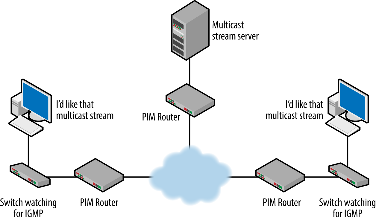
Figure 8-1. Sample topology for this chapter
Nodes interested in the multicast stream will signal their interest via the network by trying to connect using IGMP. By default, switches forward multicast traffic throughout the Layer 2 broadcast domain. If we remember our TCP/IP model, IGMP is similar to the Internet Control Message Protocol (ICMP) in that it is encapsulated in an IP packet and is considered part of Layer 3. This encapsulation is shown in Figure 8-2.

Figure 8-2. Layer 2 IGMP encapsulation
In this example, the IGMP message came from host 129.21.25.252. As the encapsulation shows, IGMP resides inside of the IP packet. As we can see, the “all hosts” destination multicast address of 224.0.0.1 being used. This is one of the many reserved multicast addresses we see used in networks today. This along with the IGMP packet types and operation will be explained later in this chapter.
Note
In order to support IGMP, all hosts are already a part of the 224.0.0.1 multicast group.
The importance of PIM is to facilitate the transmission of the Layer 3 multicast packets in the routing domain. Routers are configured for multicast and exchange information regarding the processing of multicast packet. PIM encapsulation can be seen in Figure 8-3.

Figure 8-3. Layer 3 PIM encapsulation
In this example, a testbed router (10.6.4.254) sent this PIMv2 HELLO message, which uses another reserved multicast address: 224.0.0.13. We will cover PIM in greater detail in subsequent sections.
Consider the problem of routing multicast traffic. Remember that by default routers do not forward multicast traffic. Routing protocols and static routes provide pathways to unicast destinations. So, routers do not know how far multicast traffic should be forwarded. A typical unicast routing table is shown in Figure 8-4.

Figure 8-4. Router IPv4 unicast routing table
All of the destinations listed (172.29.0.0, 172.30.0.0, and 172.31.0.0) are specific to a single unicast address space: an address space comprised on unicast hosts. Standard Internet traffic travels from a unicast host address to another unicast host address. The process of handling these transmissions is unicast routing. This means that a router given a message with a destination like those shown previously (224.0.0.1 and 2240.0.0.13) would have no idea how to process the information or forward packets. At this point, the router would not understand multicast routing.
Thus hosts on opposite sides of the same router would not be able to access a multicast stream. The problem is even more challenging when the topology grows larger and traffic must cross several routers. We can see this problem in Figure 8-1. Nodes on opposite sides of a routed topology might be interested in the multicast stream. But how would nodes from all over the topology signal to the stream sources that they were interested in the traffic? How would multicast packets be forwarded throughout the topology? Unicast transmissions are tied to a single source location and an individual network will reside in exactly one location. All routers will eventually learn how to get to this destination or what router can help them find it. But multicast destinations are not part of the routing tables and we must have a mechanism for discovery of multicast sources and signaling in order to join and leave multicast streams.
To answer this, multicast-enabled routers are aware of the IGMP messaging and can answer host queries. In this way they become aware of hosts interested in receiving or transmitting multicast packets regardless of how many and their location. Routers also use PIM to communicate with neighboring routers about multicast sources.
Multicast Addressing
Although we distinguish between Layer 2 and Layer 3 addressing, it is often true that these addresses go together. This is certainly the case with multicast. We can also make a distinction between IPv4 multicast and IPv6 multicast. The addresses typically used for these are shown in the following table:
| Layer 2 | Layer 3 | |
|---|---|---|
IPv4 | Begins with 01 | 224.0.0.0–239.255.255.255 (RFC 1112), the high order bits are set to 1110 |
IPv6 | Begins with 33:33 | Begins with FF |
When a multicast IP packet is created, it is wrapped up in a multicast frame at Layer 2. What is more, the Layer 2 address is based on the Layer 3 address. Examples are shown in Figure 8-5.

Figure 8-5. IPv4 and IPv6 multicast packets
In this example, the IPv4 packet on the top has a destination address of 239.255.255.250. Remember that 239 is part of the Class D multicast IP address range. The destination MAC address begins with 01 and is tied to the Layer 3 address through the partial conversion of this address to hexadecimal. The values 255 and 250 convert to FF and FA respectively. From RFC 1112:
An IP host group address is mapped to an Ethernet multicast address by placing the low-order 23-bits of the IP address into the low-order 23 bits of the Ethernet multicast address 01-00-5E-00-00-00 (hex). Because there are 28 significant bits in an IP host group address, more than one host group address may map to the same Ethernet multicast address.
This is all very well and good, but a bit difficult to parse—let’s do a conversion example to help explain. Figure 8-5 depicts a typical multicast frame. This conversion process modifies the MAC address based on the destination IP address: 239.255.255.250. We will begin by expanding the IP address into binary. Organizing the bits in groups of four indicates the hexadecimal character boundaries. The low order 23 bits are highlighted bold italic:
1110 1111 . 1111 1111 . 1111 1111 . 1111 1010Per RFC 1112, we will convert these 23 bits to hexadecimal and insert them into the MAC address:
1110 1111 . 1 111 1111 . 1111 1111 . 1111 1010Adding these to the reserved prefix we have:
01 00 5E 7F FF FA
This gives us the final MAC address used in this particular frame. To continue, if the low order 23 bits are the same between addresses, they will map to the same Ethernet multicast address. In this example we saw 239.255.255.250 converted. But the same conversion would occur for 224.255.255.250.
IPv4 has a number of reserved multicast addresses. These address are reserved to prevent accidental use of an address used by the infrastructure for a particular purpose. Many of these addresses are used to identify either a group of nodes or a protocol. Some examples include:
- 224.0.0.0
Base Address (Reserved)
- 224.0.0.1
All Systems on this Subnet
- 224.0.0.2
All Routers on this Subnet
- 224.0.0.3
Unassigned
- 224.0.0.4
Distance Vector Multicast Routers
- 224.0.0.5
OSPFIGP OSPFIGP All Routers
- 224.0.0.6
OSPFIGP OSPFIGP Designated Routers
- 224.0.0.9
RIP2 Routers
- 224.0.0.10
EIGRP Routers
- 224.0.0.13
All PIM Routers
- 224.0.0.22
IGMP
A full list can be found at the IANA site.
The IPv6 packet at the bottom of Figure 8-5 has a Layer 3 address of FF02::1:2. The beginning of FF identifies this as an IPv6 multicast. We can see that the frame address begins with 33:33 and ends with 01:00:02, which is taken from the last portion of the Layer 3 address.
Like IPv4, IPv6 has several reserved multicast addresses:
- FF01:0:0:0:0:0:0:1
All Nodes Address
- FF01:0:0:0:0:0:0:2
All Routers Address
- FF01:0:0:0:0:0:0:C
Variable scope allocation
- FF01:0:0:0:0:0:0:FB
mDNSv6
- FF02:0:0:0:0:0:0:1
All Nodes Address
- FF02:0:0:0:0:0:0:2
All Routers Address
- FF02:0:0:0:0:0:0:3
Unassigned
- FF02:0:0:0:0:0:0:4
DVMRP Routers
- FF02:0:0:0:0:0:0:5
OSPF
- FF02:0:0:0:0:0:0:6
OSPF DRs
- FF02:0:0:0:0:0:0:9
RIP
- FF02:0:0:0:0:0:0:A
EIGRP
A full list can be found at the IANA site.
As you can see, the reserved IPv4 and IPv6 multicast addresses have similar purposes.
Structure
As stated previously, a multicast topology requires that several components and protocols operate together. In the following sections, we will explore the structure and operation of both IGMP and PIM.
Structure: Internet Group Management Protocol
Officially, IGMPv3 is the current version, though there are some cases where interoperability with a previous version is desired. Version 3 is described in RFC 3376, which obsoletes RFC 2236. However, we will take some of the language from an even earlier document: RFC 1112 Host Extensions for Multicasting. This is because several of the multicast concepts originated in RFC 1112. RFC 1112 also describes IGMPv1. Some important rules from RFC 1112 are:
Membership of a host group is dynamic; hosts may join or leave groups.
There is no restriction on the location or number of members in a host group.
A host may be a member of more than one group at a time.
A host need not be a member of a group to send datagrams to the group.
A host group may be permanent or transient.
A permanent group has a well-known, administratively assigned IP address.
As mentioned earlier, routers will eventually get involved in the forwarding of multicast datagrams but only if the time-to-live (TTL) field is greater than 1. A TTL of 1 is the default for multicasting. As we build our examples later in this chapter, this becomes a critical piece of information.
Importantly, RFCs 1112, 2236 (version 2), and 3376 (version 3) only discuss what we might call local area network multicast. Inter-network multicast (dealing with the routing and addressing) is covered by another set of RFCs that are concerned with Protocol Independent Multicast.
RFC 1112 does include some host conformance levels that indicate the level of support for multicast. These are not immediately apparent in the packet structure. These levels of support are:
0—no support
1—support for sending but not receiving (hosts cannot join groups)
2—full support
IGMP version 3
As we read through some of the RFC content, each version sought to make improvements or add to the protocol capabilities. From RFC 3376:
This document specifies Version 3 of IGMP. Version 1, specified in [RFC-1112], was the first widely-deployed version and the first version to become an Internet Standard. Version 2, specified in [RFC-2236], added support for “low leave latency”, that is, a reduction in the time it takes for a multicast router to learn that there are no longer any members of a particular group present on an attached network. Version 3 adds support for “source filtering”, that is, the ability for a system to report interest in receiving packets *only* from specific source addresses, as required to support Source-Specific Multicast [SSM], or from *all but* specific source addresses, sent to a particular multicast address. Version 3 is designed to be interoperable with Versions 1 and 2.
The whole point of IGMP is to allow Internet hosts to signal their group request for membership. With this signaling, the node is placed into a multicast group. By default, all hosts are part of the ALL HOSTS group, which uses IP address 224.0.0.1. A particular node or router can be part of several multicast groups. To support this, IGMP has functions for joining and leaving a group. With version 3 of the protocol, nodes have greater control over the multicast streams—which streams a node wants and which streams a node wishes to exclude.
Generally speaking, IGMP is a simple protocol that defines a small number of messages. These messages include MEMBERSHIP QUERY, MEMBERSHIP REPORT (Versions 1, 2, and 3), and a version 2 LEAVE GROUP. While version 3 has been around since 2002, version 2 is still widely used and so this chapter will provide examples for both versions. The base format of an IGMPv3 query message is shown in Figure 8-6. A QUERY message is used to learn which groups have members on a particular network. Hosts that have membership in a particular group respond to queries. In the case of the specific query such as the one shown in Figure 8-8, the QUERY is asking about the membership in only the group or IP address specified.
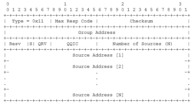
Figure 8-6. RFC general format for an IGMPv3 query
Each query message includes the following fields:
- Type
8 bits. The following messages are defined in RFC 3376:
Type Number (hex) Message Name 0x11
Membership Query
0x22
Version 3 Membership Report
0x12
Version 1 Membership Report [RFC-1112]
0x16
Version 2 Membership Report [RFC-2236]
0x17
Version 2 Leave Group [RFC-2236]
Queries are used to solicit group membership information. Membership reports are used to announce that a host is part of a multicast group. Membership reports are generated upon joining a group and after timer expiration. Routers record this information so that they can understand end hosts that desire to participate in a particular multicast stream.
- Maximum Response Code or Time
8 bits. In membership queries, this field is used to specify the maximum amount of time for a corresponding report. The time increment is 1/10 of a second. All other messages set this value to zero. It is primarily used to keep the routers up to date regarding group membership and the required forwarding of multicast streams.
- Checksum
16-bits, the one’s complement of the one’s complement sum of the 8-octet IGMP message. When computing the checksum, the checksum field is zeroed.
- Group Address
32 bits, this is the IP address used for the group. In a HOST MEMBERSHIP QUERY, this field is set to 0s and in a HOST MEMBERSHIP REPORT this value is filled in.
- Reserved
Set to 0 for transmissions and ignored at the receiver.
- S-flag
1 bit, suppresses router side processing; when set it tells the router to suppress the corresponding normal timer updates
- Querier’s Robustness Variable (QRV)
Querier is the sender of the query. This 3-bit field has a maximum value of 7. The recommended value is 2 and it is used to help tune for the expected packet loss on a network. Higher values correspond to more lossy networks.
- Querier’s Query Interval Code (QQIC)
8 bits, this depicts the time between messages from the sender of the query. The QQIC is actually derived from the Querier’s Query Interval (QQI).
- Number of Sources (N)
16 bits, specifies how many source addresses are present in the Query. This number is zero in a General Query or a Group-Specific Query, and non-zero in a Group-and-Source-Specific Query.
- Source address
32-bit address that is the multicast stream origin, the number of addresses here should match the number of sources field.
- Additional Data
Included in the checksum calculation but ignored otherwise.
Figure 8-7 depicts an actual IGMPv3 GENERAL MEMBERSHIP QUERY. If we were to expand the IP header for this IGMP packet, the IP protocol ID field value would be 2.

Figure 8-7. Packet showing IGMPv3 membership query
The last field (Num Src) of the packet is highlighted to show the “additional data” field.
Figure 8-8 depicts a SPECIFIC MEMBERSHIP QUERY. This query addresses membership in the multicast group used for the chapter stream example that we will see later.
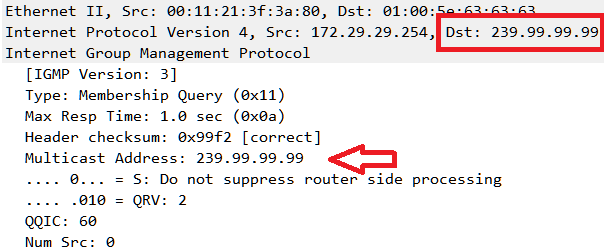
Figure 8-8. Packet showing IGMPv3-specific membership query
The difference between these two queries is that the Layer 3 addressing for the specific query is aimed at a particular group address: 239.99.99.99. This is seen in both the IP header and the IGMP packet. Remember that the goal of the QUERY is to discover group members (general or specific groups) on the network.
The general format for the MEMBERSHIP REPORT is shown in Figure 8-9. Membership reports contain the groups to which a host belongs. Figure 8-9 also indicates that each record contains the information on the right side of the image.
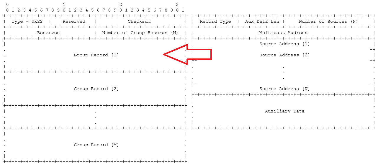
Figure 8-9. RFC general format for IGMPv3 membership report
The following fields have been added for the MEMBERSHIP REPORT message type:
- Number of group records
16 bits, contains the number of records.
- Group record
Each one of the group records contains the information seen on the righthand side of Figure 8-9.
- Record type
There are several types of record. Record type indicates the reception state of an interface that would participate in the multicast traffic. These are typically for the filtering of a multicast address:
1—MODE_IS_INCLUDE
2—MODE_IS_EXCLUDE
3—CHANGE_TO_INCLUDE_MODE
4—CHANGE_TO_EXCLUDE_MODE
5—ALLOW_NEW_SOURCES
6—BLOCK_OLD_SOURCES
RFC 3376 has the following brief explanation regarding INCLUDE and EXCLUDE modes:
In INCLUDE mode, reception of packets sent to the specified multicast address is requested *only* from those IP source addresses listed in the source-list parameter. In EXCLUDE mode, reception of packets sent to the given multicast address is requested from all IP source addresses *except* those listed in the source-list parameter.
The next couple of fields would be added for these options.
- Auxiliary Data Length
Length of the extra data at the end of the record, which may be 0; IGMP does not define this data.
- Number of Sources
The total number of IP addresses listed as a source.
- Source Addresses
32-bit IP addresses listed as the multicast stream origin.
Figure 8-10 displays an IGMPv3 MEMBERSHIP REPORT.
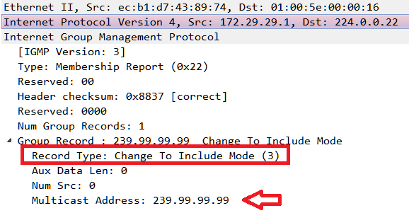
Figure 8-10. Packet showing IGMPv3 membership report
In this packet the record fields have been expanded showing the record type (3) and the multicast address for the stream group.
IGMP versions 1 and 2
For comparison and for compatibility, the packet formats for versions 1 and 2 are included in this section. Fields descriptions are included to show the differences between versions.
Version 1
Figure 8-11 depicts the general format for version 1.

Figure 8-11. RFC 1122 general format
The following fields are part of this general format.
- Version
4 bits, indicates the version of IGMP.
- Type
4 bits, message type for this packet. A value of 1 indicates a HOST MEMBERSHIP QUERY and a value of 2 indicates a HOST MEMBERSHIP REPORT.
An example of an IGMP version 1 HOST MEMBERSHIP REPORT can be seen in Figure 8-12.

Figure 8-12. Packet showing IGMPv1 membership report
The value of 0x12 is used because the version and type fields are 4 bits.
Version 2
RFC 2236 is an update that describes the interaction between hosts and routers. If needed, IGMPv1 and IGMPv2 can interoperate. There are several changes to the header:
No version number; instead, the IP protocol ID is specified as 2
Max response time is added
Router alert included in the IP header
The general format is shown in Figure 8-13.

Figure 8-13. RFC 2236 general format
Examples of IGMPv2 membership queries are shown in Figure 8-14.

Figure 8-14. Packets showing general and specific IGMPv2 membership queries
The address used in the left packet is to the general “All Hosts” address of 224.0.0.1 as this is not a specific query. In addition to the addressing used we can see the values of 10 and 1 seconds for the Max Response Time. These correspond to the hexadecimal values of 64 and 0a, respectively. Recall that the time increment is 1/10 of a second. Calculating the value for the general query we have ( (6×161) + (4×160) ) × .1 = 10.
Examples of a MEMBERSHIP REPORT and LEAVE messages are shown in Figure 8-15.
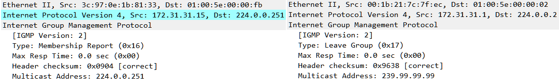
Figure 8-15. Packets showing both the IGMPv2 membership report and leave group messages
The LEAVE message appears when the stream is no longer needed. This message signals to the local router that the host no longer desires to receive this particular stream, though other hosts may. The destination address of 224.0.0.2 is to All Routers.
IP Router Alert
IGMP messages are sent with the IP router alert option set in the IP header. The router alert option is defined in RFC 2113. The RFC discusses the problem of getting routers more involved with a particular type of traffic without incurring much additional overhead. The problem is that the routers are limited by the next hop knowledge possessed by the routers. To quote from RFC 2113:
The goal, then, is to provide a mechanism whereby routers can intercept packets not addressed to them directly, without incurring any significant performance penalty. This document defines a new IP option type, Router Alert, for this purpose. The Router Alert option has the semantic “routers should examine this packet more closely”.
Protocol Independent Multicast and IGMP messages get routers more involved without significantly impacting the standard operation of the routers. An example of an IP packet with the Router Alert option set is shown in Figure 8-16.
The type, length, and value (router shall examine packet) seen in the router alert option fields are the same for all messages and specified by the RFC.

Figure 8-16. Packet showing IGMP with the router alert option
IGMP Snooping
So, how do we deal with the bandwidth consumption problem presented by all of this multicast traffic? Remember that multicast traffic is forwarded everywhere throughout the Layer 2 topology. Another question is why nodes bother sending a MEMBERSHIP REPORT when all you have to do is grab the multicast frames streaming all over the network? IGMP snooping is a technique used by switches to learn the locations of multicast sources and destinations by examining IGMP messages. By observing the join and membership messages, the network can direct the multicast traffic to interested nodes. Other parts of the network will not receive the traffic because the switch will block the multicast traffic on those ports. This technique conserves bandwidth. Should a node in another part of the network issue a join request, the multicast traffic will also be sent down the associated port. The opposite is true if a node leaves the multicast group. Because membership in multicast groups is dynamic, IGMP snooping responds by dynamically removing ports. Static membership for ports can also be created. This might be used if the administrator knew of desired and more permanent membership demands. Routers can engage in the same sort of throttling as they communicate directly with hosts via IGMP and other routers via PIM. In this way, excessive multicast traffic is prevented from interrupting Layer 3 traffic.
Structure: Protocol Independent Multicast (PIM)
Configuring routers to forward multicast traffic requires some extra steps and some additional processes. The last stop on our protocol structure tour is Protocol Independent Multicast (PIM). Like IGMP, PIM is encapsulated in IP packets but the protocol ID used is 103. The destination address for PIM messaging is 224.0.0.13. As stated earlier in this chapter, PIM is used to complete the Layer 3 requirements for multicasting between routers. This section will examine this protocol and we will go through a layer 3 topology example later in the chapter.

Figure 8-17. The multicast routing problem
As we can see, the routers possess unicast routing tables and do not have any idea how to get the multicast stream from the 172.31.31.0 network to the 172.29.29.0 network. This is where PIM comes in. PIM is a multicast routing protocol that uses the underlying unicast (or multicast) routing information base to connect multicast recipients and sources across the routed topology. PIM has several modes of operation: sparse, sparse-dense, and dense. Both sparse and dense modes are described in their own RFCs:
RFC 3973 PIM Dense Mode (PIM-DM)
RFC 7761 PIM Sparse Mode (PIM-SM)
RFC 7761 describes one method to deploy PIM. To quote:
It builds unidirectional shared trees rooted at a Rendezvous Point (RP) per group, and it optionally creates shortest-path trees per source.
An important idea, at least for sparse-mode, is the Rendezvous Point (RP). The RP serves as the root of the tree. The tree is non-source specific and so can be established anywhere in the routed topology. Data from the sender/source is sent to the RP. In addition, those wishing to join the multicast group send their join requests to the RP. In this way the multicast stream is connected. Dense-mode does not utilize a Rendezvous Point, making it less complex to configure at the expense of extra traffic being sent into the Layer 3 topology.
In either mode, designated routers act on behalf of the group hosts to ensure that the multicast traffic is forwarded on. This also means that in addition to the unicast routing tables seen in the topology diagram, each router possesses a multicast routing table. An example of a multicast routing table entry can be seen in Figure 8-18.

Figure 8-18. Router IPv4 multicast routing table
Routers exchange PIM messages and while there are many types, these messages share a common format, shown in Figure 8-19.

Figure 8-19. RFC PIM common header
The fields listed are explained here:
- Version
The current version of the protocol is 2.
- Type
The following messages are defined for PIM:
Message Type Destination 0 = Hello
Multicast to ALL-PIM-ROUTERS
1 = Register
Unicast to RP
2 = Register-Stop
Unicast to source of Register packet
3 = Join/Prune
Multicast to ALL-PIM-ROUTERS
4 = Bootstrap
Multicast to ALL-PIM-ROUTERS
5 = Assert
Multicast to ALL-PIM-ROUTERS
6 = Graft (used in PIM-DM only)
Unicast to RPF'(S)
7 = Graft-Ack (used in PIM-DM only)
Unicast to source of Graft packet
8 = Candidate-RP-Advertisement
Unicast to Domain’s BSR
- Reserved
Set to 0.
- Checksum
16-bits, the one’s complement of the one’s complement sum of the 8-octet IGMP message. When computing the checksum, the checksum field is zeroed.
For a base configuration, the common messages include the HELLO and the JOIN/PRUNE. HELLO messages are periodically sent out all interfaces configured for multicast, which allows routers to learn of multicast neighbors. HELLO messages are also used in sparse mode to elect routers that will act as the multicast designated routers. The general format and an example of a HELLO message from the topology can be seen in Figure 8-20.
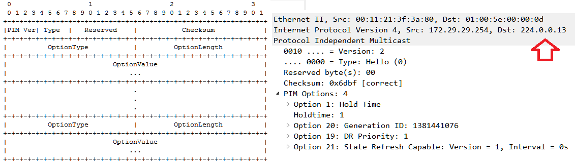
Figure 8-20. RFC general format and packet for PIM HELLO
PIM HELLO messages can contain several options. There is a wide variety and an official list is maintained by IANA outside of the RFC and a complete list is located on the IANA site.
The following table presents a few examples:
| Value | Purpose | Reference |
|---|---|---|
1 | Hold time | RFC 7761 |
2 | LAN Prune Delay | RFC 3973 |
19 | DR priority | RFC 7761 |
21 | State refresh | RFC 3973 |
22 | Bidirectional capable | RFC 5015 |
For our example, the only significant field is the hold time. The hold time value is the length of time before the next expected HELLO message. The RFC suggests a length of 30 seconds. HELLO messages can also be triggered by events such as bootup of connections. This interval is 5 seconds. In this example, we also see a Generation ID. The Generation ID is a random value that refers to the interface used for the HELLO message. Because we are using DENSE mode for our PIM deployment, we are not concerned about DR priority.
JOIN/PRUNE messages are used when hosts wish to be part of a multicast group or have lost interest in the source. The general format and an example can be seen in Figure 8-21.

Figure 8-21. RFC general format and packet for PIM JOIN/PRUNE
JOIN/PRUNE messages are both type 3 messages. The purpose is indicated in the Num Joins and Num Prunes fields. As the names suggest, in one case the stream is desired (JOIN) and in the other it is not (PRUNE). These messages directly impact the routers forwarding of multicast streams. Routers send these messages to their upstream neighbor. It is important to note that upstream and downstream are relative to the direction of the multicast stream.
In this example, we can see the standard IGMP header followed by options that are tailored for this JOIN/PRUNE message. The source IP for this message was 172.30.30.253 and it was sent to the PIM destination address of 224.0.0.13 but it was a notification for the upstream neighbor 172.30.30.254.
The upstream neighbor is closer to the root of the multicast tree. This field is actually 8 bytes long instead of the typical 4 bytes necessary for an IP address. The extra bytes are for the address family; encoding type; the Reserved, S (Sparse), W (Wildcard), and R (Rendezvous Point) bits; mask length; and finally, the source address. The address family is IANA assigned and the encoding matches the address family. This address family is IPv4 (value=1) and the native encoding is 0. In this example (172.30.30.254/32 (SWR)), only the mask length is specified with the other bits being set to 1. The hexadecimal values seen in a capture would be:
01 00 07 20 ac 1e 1e fe
The hold time is the length of time that the PRUNE state must be kept alive failing a receipt of a JOIN or GRAFT message. GRAFTing (type 6 message) is the process of rejoining a pruned stream. JOIN/PRUNE messages can be used to indicate more than one group at a time. Thus the Num Groups field can be greater than one and the Num Joins (per group) field can also be greater than one.
A note on timers
Both IGMP and PIM have a collection of timers. The messaging between systems is there in order to help determine where multicast streams should flow. Nodes join groups and routers join these same groups. Some systems can be configured such that network devices can leave without notification and timers exist so that devices do not have to constantly signal their group membership interest. At the same time, conservation of resources dictates that group membership should not persist indefinitely without occasional notification from group members. As a result, the timers associated with these protocols have the task of keeping track of and aging out membership and advertised information. Many of these timers (advertisement/solicitation rates, aging time, etc.) are configurable parameters.
A note on state
Both PIM dense-mode and PIM sparse-mode dramatically change the way that routers handle the forwarding of traffic because there is an addition to their forwarding information base. Like other routing protocols, such as Open Shortest Path First (OSPF), this is due to the router’s knowledge of its “State” or what the router understands about its network connections. For multicast, the state is contained within the Tree Information Base (TIB). The TIB has a slightly different structure in the two modes because of the different approach taken, most notably the Rendezvous Point (RP).
Generally speaking, the router keeps track of multicast stream sources, networks that contain hosts requesting the multicast stream, and any RPs in the topology. Routers do not need to keep track of individual hosts. Each active interface is part of the state and has timers associated with the traffic that might be forwarded. Both modes of operation specify a “General Purpose State” in which the routers are aware of HELLO message timers and network conditions. The state is modified by the IGMP/PIM messages seen or the expiration of timers.
Operation
Let’s work through a couple of examples. To start, we simply have a small local area network without routing or external connectivity, as shown in Figure 8-22.
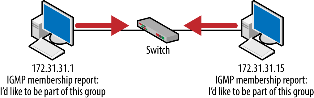
Figure 8-22. Initial multicast topology
If we assume that initially there are no multicast sources, there isn’t much to see. But the network nodes do not know this. When a node joins the network it performs a multicast announcement just in case. The specific behavior is somewhat dependent on the operating system and configuration. For the most part, this consists of a small number of MEMBERSHIP REPORTS. The output from a Windows 10 host is shown in Figure 8-23.

Figure 8-23. Windows 10 default multicast messages
These correspond to addresses reserved for multicast DNS (RFC 6762) and link-local multicast name resolution (RFC 4795). Because this node did not receive an answer ( no messages from other nodes and a multicast router is not present), this traffic does not get repeated very often.
In our second example, we will add a multicast source to this basic topology (Figure 8-24). Recall that initially the IP TTL values for IGMP messages are all set to 1, meaning that everything happens locally. The only modification to our initial topology is that one host (172.31.31.15) will be providing a multicast stream. The other host (172.31.31.1) will signal its desire to be a member of that multicast group.

Figure 8-24. Multicast topology with nodes signaling interest
To set this up, we will be using VLC to provide the multicast stream. We will also use VLC to connect to the stream. Remember that we do not have a router and so this is pretty straightforward. The only real trick is that instead of connecting to a unicast address, we will connect to a multicast destination IP. A portion of the stream configuration is shown in Figure 8-25.
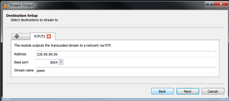
Figure 8-25. VLC multicast configuration
The server is configured to generate a Real-Time Transport Protocol (RTP) stream via the multicast IP address of 239.99.99.99 and using port 5004. RTP is used for a variety of real time data transmissions including Voice over IP. The multicast address is selected by the systems or network administration at the time of configuration. Recall that the multicast address space runs from 224.0.0.0 to 239.255.255.255, though many of these are reserved. The list of reserved address can be found at http://www.iana.org/ and far exceeds those included in this chapter. Administrators are well advised to take a look at addresses. This list provided the basis for the address used for our example.
Once the stream begins, this traffic will commence from the server, even without any clients present.
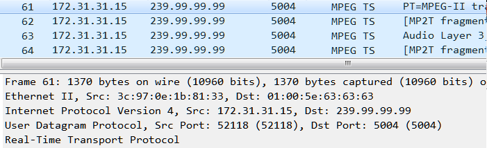
Figure 8-26. Multicast RTP stream
On the network, packets are coming from the host 172.31.31.15 but to a destination of 239.99.99.99 and port 5004. Clients joining the group will simply listen to this collection of packets instead of ignoring them. Because they are multicast frames, they are transmitted throughout the network. Nodes wishing to join send a MEMBERSHIP REPORT for the stream source.

Figure 8-27. IGMP leave group message
When the client is done listening to the stream, it disconnects with a LEAVE GROUP message. This example depicts version 2 packets but version 3 behaves in the same way.
Adding a Router
As we have seen, there is not much to the Layer 2 IGMP and multicast operation. It is now time to take a first step toward Layer 3 multicast operation by involving the router. During the first stages of the connection, group membership must be established. Multicast routers send out MEMBERSHIP QUERY messages to the local network. Hosts respond with MEMBERSHIP REPORT messages in order to indicate the groups to which they belong.
Once a router is added to the topology things change because there is the potential need to forward multicast into the unicast-based routed domain. Once multicast is enable on the router with the following commands:
ip multicast-routing
int f0/0
    ip igmp version 3
    ip pim dense-mode
The router becomes active in the topology and tries to determine the multicast needs on the live interfaces.

Figure 8-28. Step 1 – router discovery of nodes interested in the stream
From the router, QUERY messages are sent to the all hosts using an address of 224.0.0.1 and a TTL of 1. Recall that by default network nodes are members of this group. The host-based REPORT messages generated in response are sent to the IP address of the host group also using a TTL of 1 and the appropriate multicast MAC address. Per RFC 1112, hosts try not to flood the network with all of these multicast responses by using random values in timers associated with the IGMP message.

Figure 8-29. Packets generated at this point in the connection
In these first two packets we can see the change to the IP addresses and the corresponding MAC addresses. While both MAC addresses begin with 01:00:5E, the latter half is changed to reflect the layer addresses of 224.0.0.1 and 244.0.0.251. What follows is a list of the packets exchanged between the router and the 172.31.31.15 host. From this exchange it is clear that the host is attempting to join the groups indicated by the addresses of 224.0.0.251, 224.0.0.252, and 239.255.255.250.

Figure 8-30. Packet list from this point of the connection
These groups correspond to addresses reserved for multicast DNS (RFC 6762), link-local multicast name resolution (RFC 4795), and what is called the organizational-level scope (RFC 5771), respectively. This last address sounds complex but the idea is that addresses in the 239.0.0.0–239.255.255.255 range are to be used in a single local domain.
At this point, there are no active groups or multicast sources on this particular topology. Thus, the multicast traffic (which can be expensive in terms of bandwidth) will die down. However, routers will continue to query the network periodically for group membership. Should a node or router wish to join a group, this desire is signaled immediately without waiting for the membership query.
A Layer 3 Example
In our fully routed example, shown in Figure 8-31, we will now have to solve the problem of getting to another unicast network.
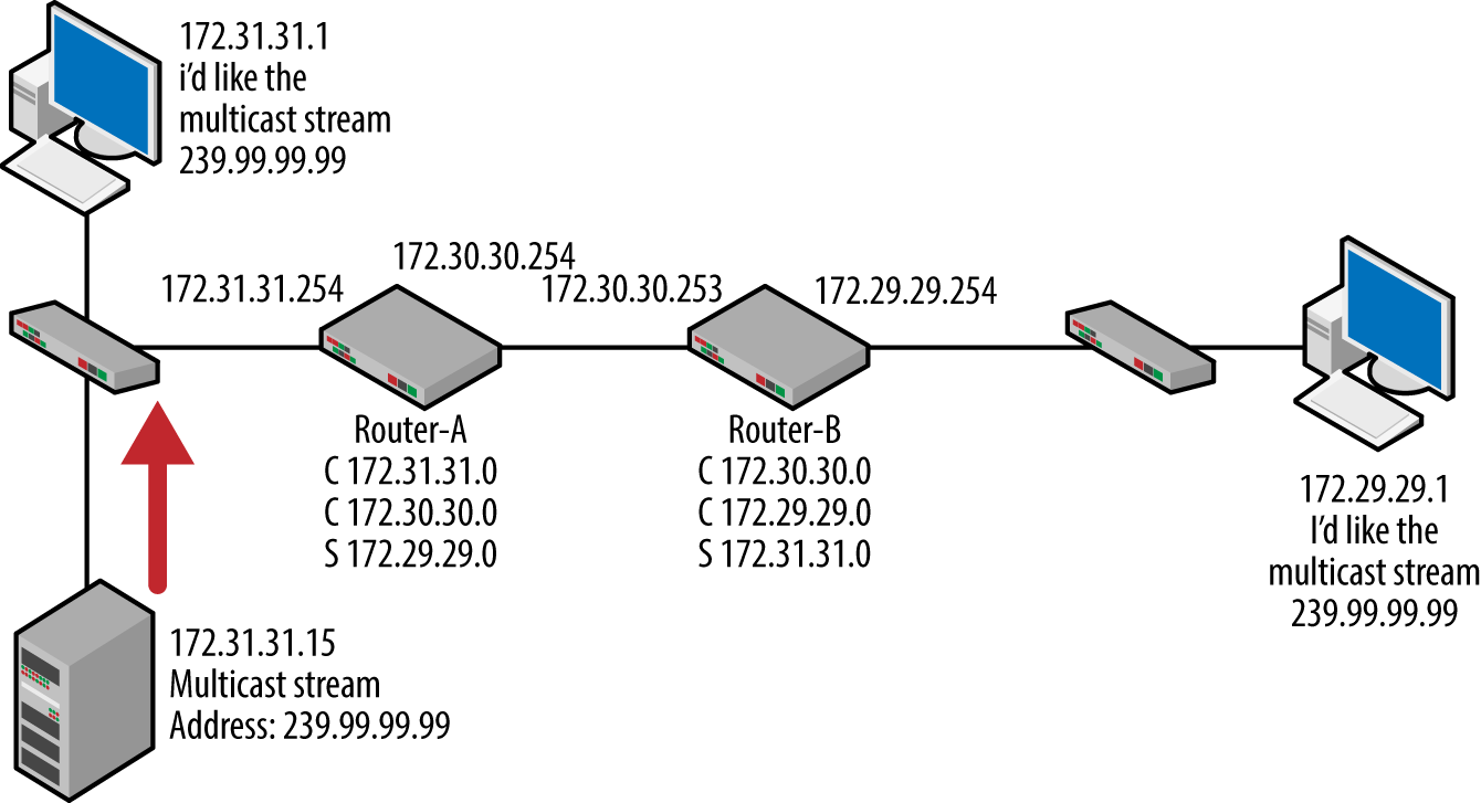
Figure 8-31. Solving the layer 3 multicast routing problem
In this case, we will be using PIM-dense mode. Both of the routers have multicast routing enabled and the interfaces active. The significant portions of the configurations for both routers are shown in Figure 8-32.
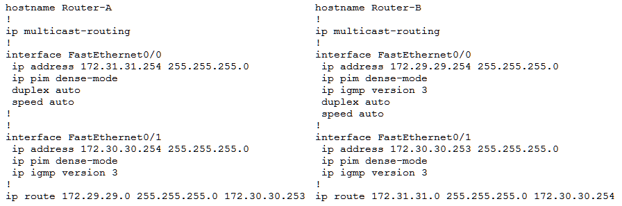
Figure 8-32. Router configurations used for this chapter
Note that with these configurations, we first solve unicast routing and then multicast routing.
Dense-mode makes the router configuration reasonably straightforward and as the setup is completed, we can examine the network for the correct transmissions and requests. Starting with the host that will receive the multicast stream (172.29.29.1) we can see that it attempts to join the correct multicast group.

Figure 8-33. Packets from 172.29.29.1 during connection attempt
This packet list depicts the QUERY from the router regarding groups membership for 239.99.99.99, the host MEMBERSHIP REPORT for the same group, and the subsequent LEAVE message when the host severed the connection. The EXCLUDE mode indicates that the host would be willing to accept any source.
Figure 8-34 depicts the traffic between the routers in which we can see the PIM message exchange.
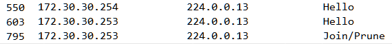
Figure 8-34. Packet list for PIM messages sent between the routers.
At the source we can see that the RTP stream is flowing (Figure 8-35).

Figure 8-35. RTP packets from the source
Everything looks great except that the recipient cannot receive the multicast stream. Looking in-between the two routers we also notice that the RTP stream is not being forwarded by Router-A. A little more investigation and we can find the source of the problem. The RTP stream has an IP time-to-live set to 1, which means that the routers will stop forwarding the traffic at the first hop.

Figure 8-36. RTP packets with low TTL value
So, even though the routers and host were cooperating for this configuration, the stream source was not and the destination could not receive the stream. To complete this build, it was necessary to increase the time-to-live (TTL) at the source in the VLC configuration.

Figure 8-37. RTP packets with the proper TTL value
Once the TTL update is done, the multicast stream can reach all of the destinations. As a last check, we can take another look at the router multicast routing tables with the show ip mroute command, as shown in Figure 8-38.
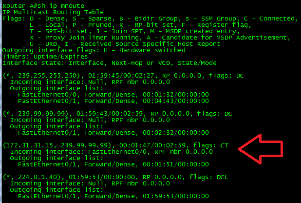
Figure 8-38. Updated router IPv4 multicast routing table
At this point we can see that the multicast source is identified as 172.31.31.15 and that the router is processing the destination 239.99.99.99. The receiver now picks up the multicast stream.
Security Warning
Most protocols have some weaknesses in either their structure (fields, etc.) or their basic operation. IGMP and PIM are no different. Both are clear text and have fields that are reserved or filled with zeros. Once configured, the sum of the operation is automatic. Messages can be forged and some devices can be victimized by denial-of-service attacks. By forging messages, routers can be tricked into believing that group members exist where they should not.
PIM messages can also be forged and RFC 3973 states that routers should not accept messages without having first received a valid HELLO message. It is also possible that architectures using the PIM-SPARSE mode may be more vulnerable as they have the Rendezvous Point, which represents a single point of failure.
Because both protocols are encapsulated in IP, the RFCs have guidelines for operation with an IPSec Authenticated Header. In addition, RFC 4609 provides some guidelines for security with PIM sparse mode.
IPv6
IPv6 makes ample use of multicast, though it is primarily for router discovery and learning about other hosts on the network. This process is called NEIGHBOR DISCOVERY and includes several ICMPv6 message types. The IGMP functionality of group membership is served by the IPv6 Multicast Listener Discovery (MLD) which is described in RFC 4604. MLD version 2 performs the functions of IGMPv3.
Summary
Multicast traffic can be both challenging to run successfully and once running can consume valuable network resources at an alarming rate. Multicast is a challenge because traditional IP networks operate based on the principle of reaching unicast destinations. By default, routers have no knowledge of multicast destinations. Routers must be told how and to where this traffic should be forwarded. Multicast can be damaging because in many ways it is treated like Layer 2 broadcast frames in that multicast is sent everywhere within the Layer 2 domain. This “forwarding everywhere” approach can consume network resources and clog network pathways. At Layer 3, multicast traffic can cause the same problems.
Addressing both the challenge of reaching multicast destinations and the cost of multicast traffic are the Internet Group Management Protocol (IGMP) and Protocol Independent Multicast (PIM). Together these protocols provide mechanisms for hosts to signal their interest in joining multicast groups and to receive multicast traffic. In addition to Layer 2, these protocols can also facilitate transmissions over a Layer 3 routed infrastructure. This chapter explained the structure and operation of both IGMP and PIM. Several examples were included that covered Layer 2 and Layer 3 operations. These explanations are supported by packet capture and configuration examples for the various network segments.
Reading
- RFC 1112: Host Extensions for Multicasting
- RFC 2236: Internet Group Management Protocol, Version 2
- RFC 3376: Internet Group Management Protocol, Version 3
- RFC 2113: IP Router Alert Option
- RFC 4604: Using Internet Group Management Protocol Version 3 (IGMPv3) and Multicast Listener Discovery Protocol Version 2 (MLDv2) for Source-Specific Multicast
- RFC 3973: Protocol Independent Multicast—Dense Mode (PIM-DM): Protocol Specification (Revised)
- RFC 4609: Protocol Independent Multicast—Sparse Mode (PIM-SM) Multicast Routing Security Issues and Enhancements
Review Questions
What are the current working versions of IGMP and PIM?
What IPv4 address is used for All Hosts?
What IPv4 address is used for PIM messages?
A streaming server uses a multicast address for the source IP.
TRUE
FALSE
Network hosts signal their interest in a multicast group via an IGMP query.
TRUE
FALSE
Routers can act as both multicast routers and clients.
TRUE
FALSE
Hosts can be a member of more than one multicast group.
TRUE
FALSE
What is a Rendezvous Point?
PIM dense mode does not require a Rendezvous Point.
TRUE
FALSE
A router that forwards both unicast and multicast traffic can do so with entries from a single routing table.
TRUE
FALSE
Review Answers
Versions 3 and 2, respectively
224.0.0.1
224.0.0.13
FALSE—A streaming server sends to a multicast address.
FALSE—Network hosts signal their interest in a multicast group via an IGMP MEMBERSHIP REPORTS.
TRUE
TRUE
A Rendezvous Point is the root of a multicast tree. Senders forward multicast traffic to it and receivers get the multicast traffic from it.
TRUE
FALSE—Multicast routers have both a unicast and multicast routing table.
Lab Activities
Activity 1—The Internet Assigned Numbers Authority
Materials: A computer with an Internet connection
Visit the IANA websites described in this chapter. See if you can find the following:
IPv4 reserved multicast addresses
IPv6 reserved multicast addresses
PIM Hello options
Activity 2—Your Multicast
Materials: A computers with a network connection, Wireshark
Start Wireshark and capture on your active network connection.
Filter for the IGMP messages.
Why are these messages there? What is their purpose? Can you find them on the lists from the previous activity?
Troubleshooting: If you cannot capture IGMP on your host, see if you can capture from another on the same network. Multicast traffic should pass through most Layer 2 network devices.
Activity 3—Streaming Media
Materials: VLC and two networked computers
Download and install VLC on both computers. One of these will be the server. VLC can be found at the VideoLAN site.
Using the guides at VideoLAN, configure one end as a streaming server.
Connect to this server from the other VLC node.
What traffic results? Can you control this traffic?
Activity 4—Mbone
Materials: A computer with an Internet connection
Investigate the current state of MBone. Some reasonable places to start looking:
What is the status of the multicast backbone project? What ISPs support multicast? Are there hopes of reinventing the architecture?
Activity 5—A Small Routed Topology
Materials: router, network nodes, and VLC
Build the topology shown in Figure 8-39.

Figure 8-39. Activity 5 topology
Configure the routers for multicast routing, ip pim, and igmp as shown in this chapter.
See if you can configure the source and clients to successfully transmit a multicast stream.