
A good engineer is a lazy degenerate. He prefers degenerate cases to special cases and will sit around (thinking) until he finds a simple solution, rather than immediately launch into a brute force approach.
In other words, the role of an architect is to use the tools he has to make things simple. (Anyone can make things more complicated!)
We are now ready to begin our exploration of network architecture. The philosophy is mostly behind us, and we can now get down to the part everyone wants to talk about. But remember, we are doing the “algebra” first. We’re trying to keep as close to first principles and independent of implementation dependencies as we can—not because implementations are bad, but because they represent trade-offs for specific situations and are data for first principles. First and foremost, we are interested in those properties that are independent of the trade-offs, and next we are interested in understanding the nature of the trade-offs and when certain choices should and should not be made. We want to postpone this binding as long as we can to see what patterns appear. The longer we can do that, the more likely the patterns we see are fundamental and not specific to a given problem domain.
This chapter covers the theory and architecture of protocols. We consider the general structure of protocols and lay the foundations for the use of the separation of mechanism and policy to reveal invariant patterns in protocols. We briefly consider the range of functions that are generally included in a protocol, although we do not consider which functions go with which kinds of protocols. We make our first stab at that in Chapter 3, “Patterns in Protocols.”
All data communications is a side effect.
The theory of finite state machines (FSMs) has traditionally been used to describe and analyze protocols. This “black box” model is not the only descriptive method, and certainly not the only implementation approach, but it does provide a reasonable theoretical framework that can be made as formal as we need. It enforces the concept that the FSM (or protocol machine, PM) itself is not an amorphous object but is created from smaller modular elements (this will become more important when we consider application layer protocols and upper-layer architecture) and that a small number of concepts can be used over and over again to construct a network architecture. We will use this model to combine modular elements of protocols and PMs into larger structures.
The traditional definition of an generally goes as follows:
A finite state machine is defined by
An input alphabet | a set A = {A1,. . . , Am} |
A set of states | S = {S1, . . . , Sn} |
An output alphabet | a set O = {O1,. . . , Op} |
Two functions: | F1(A, S) -> (S) and |
F2(A, S) -> O |
The function F1 maps an element of the input alphabet and the current state to the next state; the function F2 maps the same inputs to an element of the output alphabet.
Often, a state machine is represented by a graph (Figure 2-1), where the nodes represent the states and the arcs represent the function F1, the mapping or transition from one state to the next; and the arcs are labeled with input/output of the function F2, or by a state table with the rows (columns) representing the current state and the column (rows) are the next state. The cells are then filled by the inputs/outputs. There are many interesting properties of FSMs, and you can find more information about those in textbooks. For purposes of this book, it is assumed you are reasonably familiar with these concepts.

As noted earlier, the FSM model has been used as a formal specification method. For practical uses, it is modified slightly; and where we need it, it will be this modified form that we will use. The FSM is not practical in its pure form for describing more than fairly simple mechanisms. For more complex algorithms that involve even simple counting, ordering, and so on, an FSM would require a state space roughly the magnitude of the product of the magnitudes of each of the parameters! For example, a pure state machine model might have three major states, “start,” “doing it,” and “done.” If it also involves a single 8-bit counter, then there are 3 * 28 or 768 states. If there are two 8-bit counters, then there are on the order of 3 * 28 * 28 = 3 * 216 states or roughly 190,000 states! This makes a state analysis difficult, if not impossible, and makes it clear why this is referred to as “the state explosion problem.”
To make the model more tractable, the FSM technique is combined with programming or formal language techniques. An FSM is modified to consist of an input and an output alphabet, a set of procedures, and a state vector that includes the “major” states and any variables associated with the state, such as sequence numbers, counters, and so forth. The procedures are minimized to the greatest degree possible and modify elements of the state vector. The state vector consists of any information whose value must be maintained between inputs (This approach was first formalized by Danthine [1977], although it is a natural approach to take and may have been independently arrived at by others).
This modified state machine takes as input an element from the input alphabet and the current major state, and it invokes a procedure. The procedure executes an algorithm that uses an element of the input alphabet, the major state, and the state vector as inputs, modifies only the state vector, and emits one or more elements of the output alphabet. The state vector represents that information that must be maintained between executions of the procedures. The major states represent the point in the overall algorithm that the FSM has reached (for example, “beginning,” “waiting for something,” “middle,” “end”).
The inherent structure of protocols allows this hybrid approach to be quite successful where the FSM or program-proving techniques alone can be problematic. By combining, both state machines and the algorithms are sufficiently constrained for purposes of verification and proving both approaches remain tractable. This construct can be considered to fairly closely mimic most protocol implementation strategies, which is part of its power and usefulness. With this structure, we now set out to model protocols and communication.
For two systems to communicate, they must have a shared conceptual schema. In other words, they must already have some common understanding about their world and the things in it that they want to talk about. If one correspondent says, “Do X,” the correspondents must first know what “Do” and “X” mean, as well as what it means to “do X.”
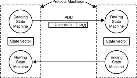
For those who want to jump ahead and propose “self-describing protocols,” there is no such thing. This merely moves the shared common schema up a level, and then the definition of the description language must be part of the shared conceptual schema. No matter how minimal, there must be some shared schema. These are often concepts relating to ordering messages, determining the acceptability of a message, detecting errors, performing some operation, and so on. These concepts held in common are embodied in FSMs. The set of rules and procedures that each system participating in the communication is required to follow to maintain the coordination of their shared schema is called a protocol. The FSMs that implement the protocol will be referred to as protocol state machines or just protocol machines (PMs). (We will use PM only for those FSMs that describe protocols and reserve FSM for those that may or may not be PMs.)
Often, the operations that are performed require that each FSM maintain information on the state of the other. Clearly, this information is seldom accurate. And as discussed later, the amount of this shared state and the degree of consistency of the information are crucial considerations. The protocol defines the procedures and interactions necessary to initialize and maintain the shared state among the sending and receiving systems. Protocols in computer communications are used for two broad classes of problems: coordination over a distance and action at a distance.
In practical terms, the protocol specification becomes the specification of the communicating FSMs (Figure 2-2). Theoretically, this is not a requirement. Specifications techniques do exist—namely, the temporal logic techniques noted previously—that can specifying a protocol without reference to constructs similar to an implementation, such as a PM. But as noted, very few can actually design with these techniques. Therefore, the FSM approach is followed throughout this book to model protocols. This is not intended to in any way constrain implementation strategies but only to serve as a model. However, keep in mind that nonstate machine implementation strategies exist.
A PM models a single instance of communication, a single flow. It is often the case that the supporting service and the user of a PM are also PMs. Therefore, we must refer to the ranking of PMs (and other objects) so the (N)-PM is the focus of our attention; the (N+1)-PM above which uses the (N)-PM; and the (N−1)-PM below which is used by the (N)-PM. All PMs of a particular protocol in a given system may be referred to as a protocol machine type (PMT). In general, a system will have more than one PMT for each protocol of a particular rank. (We will figure out what a layer is in Chapter 6, “Divining Layers.”)
A protocol may be either symmetric, also called peer where the communicating PMs have the same behavior that is, the same state machine; or, asymmetric where the communicating PMs will have distinctly different behaviors that is, different state machines.
In the latter case, it may be useful to distinguish subtypes of PMs, which are usually given names such as user/server, client/server, master/slave, and so on. Many application protocols are asymmetric, whereas data transfer protocols tend to be symmetric (or should be, as anyone who has tried to build an interprocess communication [IPC] facility on top of a synchronous Remote Procure Call [RPC] system can testify). Recognizing that some applications are inherently asymmetric and that protocols often find use in ways not foreseen by their authors, it may be worthwhile to expend the extra effort to consider whether a protocol normally seen to be asymmetric might not have a symmetrical model, because a symmetrical protocol will, in general, be more flexible and easier to use. We will see an example of this with Telnet in Chapter 4, “Stalking the Upper-Layer Architecture.”
A circuit is just one long packet.
Because communicating systems do not share state (that is, memory), one PM must be able to notify the other of important changes in state. This is accomplished by exchanging finite quanta of information. These quanta carry information that is used to update a PM’s view of its correspondent’s state. This continual exchange of information quanta between the PMs creates a weak “field” or binding between the PMs. These bindings are characterized by the amount of shared state and by the “strength” of the binding. The strength of the binding is a measure of how tightly coupled the PMs are (that is, the degree to which one PM’s perception of the state of its correspondent can be allowed to deviate from reality). It has been useful to recognize a form of binding within systems, and three degrees of bindings between systems: a minimal binding requiring no exchange of updates; a weak binding with some dependence but not affected if some updates are lost; and a strong binding, which requires updates to be received to avoid pathological behavior.
In some specifications, this binding is referred to with terms that connote a “connection” or “flow.” Although the terms can be very useful, the use of these terms can vary widely. Therefore, this book adopts the following terminology for the forms of this relation:
An association represents the minimal shared state and minimal coupling, often associated with connectionless communication.
A flow has more shared state but not tightly coupled (no feedback), as found in some network protocols.
A connection has a more tightly coupled shared state (with feedback), as with so-called end-to-end transport protocols.
A binding has the most tightly coupled shared state, generally characterized by shared memory.
A connection and a flow are specializations of an association. Whereas a connection or flow has all the properties of an association, the reverse is not true. Later, as we develop further properties of protocols, we discuss more about the differences among these three concepts.
A protocol does not exist on its own. Something else must drive it—provide it with its raison d’être. In general, this is another FSM and often another PM in the same system that requires the services that this protocol provides. (Traditionally, this driving FSM has been drawn as “above” the PM, and in this discussion it’s often referred to that way.) The PM and the FSM above must also exchange information to coordinate their behavior. However, it is prudent and important for the driving FSM to view the PM as a “black box,” thus hiding the complexity of the PM’s operation from the FSM above and hopefully simplifying the FSM. This “black box” boundary is traditionally called an interface. (Interface is used in two very distinct ways: In computer science, as described here and in telecommunications as a protocol between types of systems, generally where one system is owned by the network.) Because exchanges of information across an interface are in the same system, the mechanism for the exchange achieves a much tighter coupling than even a connection. In implementation terms, this is often referred to as a system call or as implemented by other mechanisms to effect isolation. This exchange between FSMs in the same system is often referred to as an application programming interface (API).
Therefore, for the PMs in different systems to coordinate their behavior, the input alphabet of a PM, in fact, must consist of two subsets:
The exchange of information to coordinate with the FSM above and the PM,
The exchange of information to coordinate among the PMs
Architecturally, these two exchanges are very similar, even though the mechanisms are quite different. For this discussion, the first is referred to as an interface, the second as a protocol. Because protocol exchanges are between PMs in different systems, a much looser coupling results. Interfaces may be implemented as local system or procedure calls, whereas protocol exchanges require self-contained quanta of information to be transferred between the PMs. A practical protocol specification will specify the interaction with an upper interface—that is, the user of the protocol, the interaction between the PMs, and the interaction with the lower interface (or the supporting communication service). An implementation of the protocol must exist in all the communicating systems that participate in the data transfer. This implementation is modeled as a PM. The PM (Figure 2-3) has four kinds of interactions:
The (N)-interface with the user, which may be another protocol machine, an (N+1)-PM, or an application
The exchange of messages or protocol data units (PDUs) with the peer (N)-PM(s) to maintain the shared state
The (N−1)-interface with some (N−1)-PM that provides a certain level of quality of service
The local interface, for various operating system services, such as timers
(For simplicity, rather than referring to the user, the (N+1)-PM, or the application in every case, (N+1)-PM will be used to stand for all three.)

An interface represents a separate state machine shared between an (N)-PM and (N+1)-PM or an (N)-PM and (N−1)-PM always in the same system. Of course, when an interface is defined, the specification cannot be entirely complete. The specification can characterize what an (N+1)-PM must do but clearly cannot specify everything it does. For a protocol specification, the interface specification represents a partial state machine that must be meshed with the state machine of the (N−1)-PM or the (N+1)-PM, depending on whether it is the lower or upper interface. It is important to note that for any application to interact with a protocol (that is, for the application to communicate with another application), it must incorporate the state machine necessary to interact with the protocol’s interface. When the partial state machine for the interface is joined with its upper or lower partner, it creates a strong binding between the two PMs.
This is an idealized logical model. These interfaces, and even the PM, may not be identifiable in a given implementation in a system. However, the model provides a formal framework for describing the architecture for creating the appropriate protocol specifications and is fairly easy to map into any implementation approach.
As noted earlier, to communicate from one place to another, finite quanta of information must be exchanged. Over the years, these “finite quanta” have been given a variety of names, such as frame, cell, packet, segment, message, and so on, depending on the inclination of the author and the kind of protocol. All of these are different terms for the same concept. To avoid confusion, we will adopt the neutral term protocol data unit (PDU).
The structure of a PDU (Figure 2-4) has evolved to consist of three major elements: a header, and less frequently a trailer, to carry the information necessary to coordinate the PMs, and the user data. This is an important distinction: “Information” is what is understood by the PM, and “data” is what is not understood (and usually passed to the PM or application above). To remind us of this, we refer to the part that is understood by the (N)-PM (the header and trailer) as protocol control information (PCI), and the user’s data as user-data because the (N)-PM does not understand it. This distinction is clearly relative. What is information (PCI) to the (N+1)-PM is merely part of the data to the (N)-PM. Similarly, the (N)-PCI is merely more user-data to the (N−1)-PM and so on. This distinction is crucial to much of what follows. It is important that one always be clear about what is information and what is data at any given point.

PDUs are sometimes likened to processor instructions: Based on the parameters of the instruction (PCI) and the state of the processor (PM), the execution of PDUs performs operations on the state of the processor (PM). Unlike instructions, which carry an address to reference the data on which they operate, PDUs must carry the data themselves
Various types of PDUs are used to transfer PCI among peer PMs. These PDUs may or may not contain user-data. There is no architectural limit to the size of these PDUs. There might, however, be engineering considerations that impose size limitations on the PDUs in specific environments. For example, for a protocol operating in an error-prone environment, a smaller PDU size may increase the probability that a PDU is received error free, or that the overhead for retransmission is minimized. Or in a network of real-time sensors, the systems may have very limited buffer space, so smaller PDUs may be necessary.
Most PCI is contained in the header. Most fields in data transfer protocols are fixed length to simplify processing. Fixed-length fields generally precede any variable-length fields. A length field that gives the total length of the PDU is strongly recommended. The header of any protocol should have a protocol identifier to identify the type of protocol and a protocol version to identify the version of the protocol, as well as a field that indicates the function of the PDU. The PCI will also include a field that encodes the action associated with the PDU (for example, set, get, connect). Like instructions, this field may be either horizontally or vertically encoded; that is, it may consist of either a string of control bits, each indicating functions of the processor to be invoked, or an opcode, which stands for the specific combination of functions. In general, horizontal encoding requires more space than vertical encoding because there are generally many combinations of bits that are not legal. Horizontal encoding is generally faster in hardware, whereas vertical is faster in software. TCP uses horizontal encoding. This was an experiment that has not stood the test of time. If the implementation treats the control bits as control bits, it leads to less-efficient implementation. Papers (Clark et al., 1989) have recommended treating them as an opcode, and this seems to be what most implementations do. Consequently, opcodes are generally recommended over control bits.
The PDUs of some protocols have a trailer. The most common use is to carry the cyclic redundancy code (CRC). The advantage of the CRC in the trailer is that the CRC can be computed as each byte arrives without waiting for the whole PDU to be received. Generally, the use of a trailer is found in protocols operating near the physical media. When a PDU is in memory, the advantages of a trailer are less useful. Consequently, the use of trailers in protocols higher up is infrequent.
The general guidelines for the use of a trailer might be characterized as follows; but it is important to stress that it isn’t so much the absolute characterization of the conditions as their relation to each other:
The information in a trailer is such that it cannot be known at the time the header is created; that is, it is a function of the header and the user-data.
The processing time for the PDU is much less than the time required for the PDU to be sent or received, and the delay thus incurred would be a significant fraction of the delay quota for the traffic.
Earlier service was used as the abstraction of the interface, hence, the term service data unit (SDU) is used to refer to the unit of data provided to the PM by the (N+1)-PM across the service boundary as a service data unit (SDU) (reserving the term interface for the implementation-specific case, such as a UNIX interface or a Windows interface). To a PM, an SDU consists entirely of user-data but will have a size that is convenient to the (N+1)-PM. The service primitive invoked to pass the SDU to the PM will also pass other parameters to the PM for handling the SDU. Generally, one of these is a local “port-id” that identifies this end of the flow or connection this SDU is to be sent on. The port-id is local to the system (that is, only known within the system and only unambiguous within it) and shared by the (N+1)- and (N)-PMs to refer to related communications. The PM may have to segment the SDU into several PDUs or may aggregate several SDUs into a single PDU so that the PDU is a size convenient to the requirements of the (N)-protocol. (This nomenclature follows the OSI Reference Model, not because I favor the OSI model, which I don’t, but because it is an existing nomenclature that tries to define common terms. I can find no good reason to invent new terms other than for the sake of generating new terms. For those who still have a visceral reaction to anything OSI, all I can say is, OSI is long dead, get over it.)
One of the enduring debates in protocol design is, given that the (N+1)-PM delivered an (N)-SDU of a particular size to the (N)-PM and that under some conditions it may have been fragmented or concatenated en route, what does the (N)-PM deliver to the remote (N+1)-PM? What was sent or what was received?
Although it may often be the case that an SDU would be a single (N+1)-PDU, it might be more than one. Seldom would it only be part of a PDU. In any case, the (N)-SDU was a unit that the (N+1)-PM found to be significant for its processing. The early debate was between record and stream modes, derived from early operating system practices. The older mainframe systems tended to operate on fixed-length records, whereas more modern systems such as Sigma 7, Tenex, Multics, and its derivative UNIX communicated in terms of undifferentiated byte streams. Record mode was always considered as something that simply had to be lived with. There was general agreement that record mode was too inflexible and cumbersome.
Stream mode was considered a much more flexible, elegant approach that provided greater layer independence. A stream might deliver any combination from whole SDUs to pieces of an SDU to multiple SDUs or even part of two SDUs. Stream mode requires that the (N+1)-layer be able to recognize the beginning and end of its SDU/PDUs and be able to assemble them for processing. The (N+1)-protocol must have a delimiting mechanism and cannot rely on the layer below to tell it where the beginning and end of the PDU are.
Over time, a third approach evolved, which was a generalization of record mode. In this mode, SDUs were not fixed length. The rule in this approach was that the identity of SDUs was maintained between the sending and receiving users. No name was ever given this mode, so let’s call it the idempotent mode, referring to its property of maintaining the identity of the SDU invariant. Because SDUs may be of any length, this differs significantly from traditional fixed-length record mode. This mode requires that the (N)-layer deliver SDUs in the form it received them. If the (N)-protocol needs to fragment an SDU, it is (N)-protocol’s responsibility to put things back the way it found them before delivering the SDU to the (N+1)-PM. There is something compelling about a “do anything you want but clean up your mess when you’re done” approach! This form is more consistent with good programming practice. Similarly, if the (N)-protocol combines several SDUs into a single PDU for its own reasons, it must deliver them as separate SDUs to the remote user. Consequently, the (N + 1)-PM does not have to understand (or be modified for) every potential (N)-PM fragmenting or concatenation condition, nor make assumptions about what the (N)-PM will do. Maintaining the identity of SDUs maintains symmetry in an architecture. And symmetry is always good.[1] But, it does require the assumption that the layer below is well behaved. The essential difference between the two is that the idempotent mode is a user’s point of view, whereas stream mode is more the implementer’s point of view.
It makes no difference in the receiving system, the amount of work is the same: Either the receiving PM or the receiving user, the (N+1)-PM, must do the reassembly. In other words, the work is either done at the bottom of the (N+1)-layer (stream) or the top of the (N)-layer (idempotent). There are no strong logical or architectural arguments for one or the other. Although if it is done by the (N+1)-PM, it may have to be implemented several times (if there are many (N+1)-PMTs i.e, applications). Then, good software engineering practice supports the (N)-PM performing the function.
That said, it will be easier for protocols with sequence space granularity of octets to do stream mode (for instance, TCP), and more work to keep track of where the SDU boundaries are.[2] For protocols that do sequencing to the granularity of PDUs, the amount of work is the same if there is no concatenation. If the protocol concatenates, however, it must be able to find the boundaries between SDUs. In which case, stream mode will be less work for the (N)-protocol. Overall, the work as seen by the system is the same.[3]
But it does not have to be an either/or choice. It is possible to provide both. For the solution, we take a lesson from how Telnet modeled half and full duplex as degenerate cases of a single mechanism, and from the glib comment that “a circuit is just one long packet” (mentioned previously). We just note that a stream is simply a very long SDU! If the protocol has the ability to indicate the boundaries of SDUs and negotiates whether it may deliver partial SDUs (in order) to the (N+1)-layer, the (N+1)-layer can have either interface discipline. Stream mode negotiates partial delivery and at a minimum indicates the end of an SDU only on the last PDU sent. Idempotent mode negotiates no partial delivery and indicates the end of SDUs at the appropriate times. Flags in the protocol might be defined as shown here:
A PM must interpret four inputs:
Interactions with the upper interface
PDUs from its corresponding PM(s)
Interactions with the local system
Interactions with the lower interface
All of these can be considered to be equivalent to procedure or system calls of the following form:[4]
<procedure name>(<param 1>,<param i>*)
The PDUs can be seen as procedure calls in that the PDU type is the name of the procedure and the elements of the PDU (that is, PCI and user-data) are the parameters:
<PDU type>(<PCI element><PCI element>*, user-data)
Associated with each of these are actions to be taken depending on the state of the PM (that is, the body of the procedure). The action taken by each procedure is to interpret the parameters and update the state vector associated with the PM and possibly cause other PDUs to be sent or interactions with the local system or the upper- and lower-interfaces to occur. Coordinating all of this is a control function or state machine that enforces the proper sequencing of these actions according to the state of the PM.

The local interactions access local resources, such as memory (buffer) or timer requests. Processing the PDUs invokes the mechanisms of the protocol. In some protocols, a distinct set of PDUs is associated with a particular mechanism, forming a module. Such a module is formed from a subset of PDUs and their procedures with its own state machine. Strictly speaking, any such module as this is a protocol. These service primitives and PDUs invoke the mechanisms of the protocol. For data transfer protocols, the types of interface procedures are all the same: synchronize/finish and send/receive with appropriate parameter values.
The primary task of a PM is to maintain shared state. There are three loci of shared state in any PM: the upper- and lower-interface loci, or bindings, between an (N)-PM and an (N+1)-PM and between an (N)-PM and an (N−1)-PM; and the protocol locus, often called a connection or flow, between apposite (N)-PMs. The shared state is maintained by the exchange of PCI. The shared state between PMs in adjacent layers is maintained by the parameters exchanged in procedure or system calls between layered PMs in the same system,[5] whereas the shared state between apposite PMs in different systems is maintained by the exchange of protocol PCI. The primary difference between the two kinds of shared state is that for a connection or flow, PCI may be lost. For an interface binding, it can be assumed that the exchange of PCI is reliable, and often, shared access to memory can be assumed.
State changes in a PM are caused by inputs from the upper interface (for example, an application or (N+1)-PM, or from PDUs from the apposite PMs, or from the local layer apparatus [for instance, timeouts]). Whether inputs from the layer below cause changes in state is a matter of policy. In other words, if an (N−1)-flow should be de-allocated or fail unexpectedly, it is a matter of policy whether this causes a subsequent state change in the (N)-flows multiplexed on the (N−1)-flow. It might not.
Determining the optimal size for PDUs is a traditional engineering trade-off. In general, PDU processing overhead is proportional to PCI length, but independent of PDU length. Regardless, processing efficiency is maximized by making the PDU as long as possible. Similarly, bandwidth efficiency is maximized, the greater the amount of user-data relative to the length of PCI. However, other factors mitigate toward smaller PDUs, such as the amount of data significant to the application may be small, buffering constraints in systems, fairness (that is, interleaving PDUs), the error characteristics of the media, and so on. Fragmentation (or segmenting) and concatenation may be used to match PDU sizes or improve efficiency between layers or between different subnets based on different media.
There is an optimal range for PDU size in each protocol, including applications, that will depend on where the protocol occurs in the architecture. For upper-layer protocols, this will be most strongly affected by the requirements of the application. Boundaries will tend to be created at points that have logical significance for the application. These sizes will give way to the requirements of the lower layers, while being moderated in the middle layers by system constraints (for example, the operating system and constraints on multiplexing). For lower-layer protocols, the size will be more determined by the characteristics of the subnetwork or the media. As noted previously, the PDU sizes for error-prone environments such as wireless will be smaller, thereby decreasing the opportunity for errors.
One would expect larger PDU sizes in less-error-prone media. For backbone networks where traffic density is the highest, one would expect media with very high bandwidths, very low error rates, and larger PDU sizes to take advantage of concatenation to increase efficiency. As bandwidth and traffic density increases, one wants to process fewer bigger PDUs less often rather than more smaller PDUs more often. Smaller PDUs will occur at lower bandwidths to minimize the time window for errors and increase the opportunity for interleaving other PDUs (that is, fairness). Smaller PDU sizes are more likely at the periphery, and size increases as one moves down in the layers and in toward the backbone. (Or as traffic density increases, for example toward the backbone, one wants to switch more stuff less often, not less stuff more often!) The ratio of PDU size to bandwidth and the ratio of PCI to PDU size should be relatively constant or decrease as one moves down in the architecture.
One of the factors in determining PDU size is to keep the ratio of the PCI size to the PDU size small. This ratio is an engineering choice, but as a rule of thumb, generally, 5% to 10% is considered acceptable. Address fields are the greatest contributor to PCI size. Upper-layer protocols with wider scope will have longer addresses, and lower-layer protocols with less scope will have shorter addresses. Thus, we can expect some inefficiency in the upper layers as applications generate potentially shorter PDUs (but of a size useful to the application) with longer addresses; but increased efficiency at the lower layers as PDUs get longer, concatenation occurs, and addresses get shorter. Concatenation is not supported by the current Internet protocols early on because of the slower processor speeds and later because of the delay incurred waiting for PDUs to concatenate. Given that these networks start to congest at 35% to 40% utilization, and consequently, ISPs try to operate well below that threshold, this isn’t surprising. At higher utilizations, one should be able to concatenate with only marginal impact on delay.
In operating systems, the concept of separating mechanism and policy has a long tradition. Only recently has this been used in network protocols, although there are exceptions (for example, Hadzic et al., 1999; Snoeren and Raghavan, 2004; Arpaci-Dusseau, 2003; RFC 4340, 2006; and others). However, this work has concentrated on the engineering aspects and tended to ignore what this tells us about the structure of networks and protocols. Here we develop a model for the separation of mechanism and policy, and then in the next chapter look at its implications. A protocol is composed of a set of functions that achieve the basic requirements of that protocol, whether that is error control, reading a file, flow control, two-phase commit, or so on. The choice of functions is made based on the operating region in which the protocol is intended to exist and the desired level of service that is to result from its operation. Each function is divided into a mechanism and a policy (see Figure 2-6).

Mechanisms are static and are not changed after a protocol is specified. The order of interpreting the fields of the (N)-PCI is determined by the PM (that is, defined by the protocol specification). In general, policy types occur in pairs: a sending policy and a receiving policy. For example, for the function detecting data corruption, a specific CRC polynomial is the policy. The sending policy computes the polynomial, and the mechanism inserts it into the PDU. The receiving policy computes the polynomial on an incoming PDU, and the mechanism compares the result with the field in the PCI.[6] There are exceptions. For example, a policy to choose an initial sequence number would only occur in the sending PM. Hence, initialization policies or policies associated with timeouts may not occur in complementary pairs. The number of distinct types of policy associated with each mechanism depends on the mechanism but is generally only one. The number of policies of a specific type is theoretically unlimited, although in practice only a few are used. In general, there is typically a sending policy and a complementary receiving policy for the respective sending and receiving PMs. The coordination of the mechanisms in the sending and receiving PMs is accomplished by the exchange of specific fields of information in the (N)-PCI (see Figure 2-7). A single PDU may carry fields for multiple mechanisms in the (N)-PCI. A major consideration in the design of protocols is determining which fields are assigned to which PDU types.

For any one mechanism, a variety of policies may be applied to it. For example, consider the basic sliding-window flow-control mechanism used in many protocols. The sliding window is part of the protocol specification. When specified, this mechanism is not modified. However, there are a variety of policies for flow control: from simply extending new credit on receipt of a PDU, to periodically sending new credit, to high/low watermarks, and so on. Different policies might be used for different connections at the same time. Similarly, acknowledgment is a mechanism, but when an ack is sent is policy.
In the upper layers, OSI found that it was necessary to negotiate a “context.” The presentation context selected the abstract and concrete syntax of the application, whereas the application context was to “identify the shared conceptual schema between the applications.” The concept of the presentation context was fairly well understood, but the application context never was. (see Chapter 4, for a more complete discussion of this.) Not recognizing that both cases were simply mechanisms for negotiating policy also meant that OSI failed to recognize that this was a general property of all protocols, not just of the upper two layers. Protocols should include a mechanism for specifying or negotiating policy for all mechanisms during synchronization or establishment.[7]
Policies chosen at the time communication is initiated can be modified during data transfer, if care is taken. Some policy changes may require that they be synchronized with the data stream to prevent pathological behavior. For example, changing the CRC polynomial for detecting corrupt data would require such synchronization so that receiver knew when to stop using the previous policy and use the new one. It can be shown that this sort of strong synchronization is essentially equivalent to establishing a new flow. Hence, including this capability in the protocol would generally be deemed as simply adding unnecessary complexity. However, some changes, such as changing the frequency of extending flow-control credit or of sending acknowledgments, would not require such synchronization and would not incur the same overhead. Although quite useful, it is less obvious that policy negotiation should be allowed during the data transfer phase. In general, changing policy during the data transfer phase requires synchronization that is essentially equivalent to establishing a new flow or connection.
Any ability to change policy on an existing connection or flow will have to be carefully handled to avoid aberrant behavior. The process, which determines which policies should be used or when they are changed, is outside the protocol. This may be requested by the layer above (or by the user), which knows its use of the protocol is changing. More likely, it will be effected by “layer management” to ensure that the parameters agreed with the layer above are maintained or in response to changes observed in the characteristics of the layer below and to ensure that the resource-allocation strategy of the layer is maintained.
By separating policy and mechanism,[8] the operating range of a protocol can be increased, and its ability to optimally serve a particular subset of an operating region can be greatly enhanced. The choice of policy depends on the traffic characteristics of the (N−1)-association and the quality of service (QoS) required by the user. The task of the (N)-PM is to translate these QoS characteristics as requested by the (N+1)-PM into a particular choice of mechanisms and policies based on the service from the (N−1)-PM. As a rule of thumb, one would expect protocols nearer the media to have policies dominated by the characteristics of the media and consequently fewer policies would apply. For protocols further from the media, there would be a wider variety of policies that might apply. (However, other considerations may limit the number of policies that might occur.)
There has been much talk of policy in the network literature, but generally limited to application protocols, such as routing, and recently there has been limited experimentation with applying this elsewhere. If one inspects the myriad proposals for “new protocols” that have appeared over the years, one will find that no new mechanisms have been proposed for nearly 25 years.[9] These “new” protocols are primarily rearrangements of headers and old mechanisms with different policies. Given a well-designed protocol that separated mechanism and policy, one would need many fewer protocols. It would be much easier to understand the properties of various policies and their interactions. There have been proposals for protocols with optional mechanisms and policies that are specified at execution time. In general, these protocols have considerable overhead either in bandwidth, processing, or both. This concept, along with a pragmatic approach to selecting policy, should achieve a useful middle ground. The mechanisms of a protocol are fixed at the time of specification, whereas selecting policies is postponed until synchronization or establishment. Mechanisms are fixed, although an appropriate policy could, in effect, make it null.
As an example of the power of this concept both to simply and easily achieve what might be considered a major change to a protocol and to give us deeper insights into the nature of protocols, consider the following: It had always been thought that another transport protocol would be required for voice. With voice, the PDUs must be ordered, but short gaps in the data stream can be tolerated. So, it was thought that a new protocol would be required that allowed for small gaps (instead of the protocol just retransmitting everything). However, a new protocol is not required; all that is necessary is to modify the acknowledgment policy...and lie. There is no requirement to tell the truth! If the gap is short, send an ack anyway, even though not all the data has been received. There is no requirement in any existing transport protocols to tell the truth!
This also tells us something very important about the semantics of ack: Ack does not mean, as commonly thought, “I got it”; instead, it means, “I am not going to ask for a retransmission” or perhaps more to the point, “I’m fine with what I have received.” This might seem like playing with words, but it makes a major difference in how we conceive the use of acknowledgments. Consequently, in this book what might be referred to in other protocols as the acknowledgment mechanism is often referred to as retransmission control.
Quality of service (QoS) is a term that has been applied to the set of characteristics, such as bandwidth, delay, error rate, jitter, and so forth, that the user desires the communication to have. Proposals for QoS parameters (and sometimes rather extensive proposals) have been made many times over the past two or three decades, but few protocols have paid more than lip service to doing anything about it (to some extent with good reason). If you look carefully at these parameters and ask, “When a QoS parameter is changed, which policies of the protocol change and how?” you often finds that the answer is “none.”
There are two reasons for this. Any change in policy that could affect that parameter is a resource management issue, often a change in the buffering strategy: a topic generally not addressed by protocol specifications and normally considered the exclusive domain of the implementation. There is nothing that a protocol can do to affect the parameter.
Consider delay. Clearly, a protocol can minimize making delay worse, but it can do nothing to improve it. Parameters of this latter type are called nature of service (NoS). The distinction between QoS and NoS is essentially recognition of the old adage that “you can’t make a silk purse from a sow’s ear,” but perhaps we can make the sow’s ear a bit more acceptable. These are parameters largely determined by “nature.” We may be able to avoid making them worse, but there is little or nothing that can be done to make them better.
QoS represents a set of characteristics that the (N+1)-PM desires from the (N)-PM for a particular instance of communication (the silk purse). NoS represents the set of characteristics that an (N−1)-PM is actually providing and is likely to be able to provide in the future (the sow’s ear). The (N)-PM uses the difference between the QoS and NoS to select the protocol, mechanisms, or policies to match the desire with the reality. However, limits apply to what a particular protocol can do to improve a particular NoS to match the particular QoS that is requested. The nearer the (N)-PM operates to the physical media, the more constraining the NoS may be; that is, the technology dependencies limit the amount of improvement that can practically be accomplished by a single protocol. In some cases, some forms of error control may be more efficient or more effective if they are postponed to protocols operating further from the physical media. This and the fact that multiplexing at different layers allows for better strategies for aggregating PDUs are some of the reasons that there is more than one layer on top of the physical media. On the other hand, additional layers limit the achievable bandwidth and delay characteristics, thus mitigating against too many layers. This is one of many trade-offs that are continually being balanced in the design of network architectures. We return to this topic later when we discuss particular QoS strategies.
Over the years, a number of mechanisms have been found to occur in many protocols. This section briefly reviews a few of the more common protocol mechanisms so that we have something concrete to refer to in our subsequent discussions.
A delimiter is a mechanism used to indicate the beginning and end of a PDU. There are two basic methods for delimiting PDUs: external and internal delimiting. In external delimiting, a special bit pattern, usually called a flag sequence, is defined to denote the start and end of the PDU. The problem with this approach is that either data transparency is forfeited, because the flag sequence cannot occur as a bit pattern in the PDU, or some “escape” mechanism is used to insert extra bits into the PDU to avoid the flag sequence, which are then removed by the receiver before any other PDU processing is done. Another common form of external delimiting is to use the lower layer to delimit the PDU. This may take the form of a length field in the (N−1)-PCI or in the physical layer in the bit encoding used (for instance, the use of Manchester encoding to delimit MAC frames in Ethernet). In internal delimiting, the PDU contains a length field as an element of PCI from which the number of bits or octets to the end of the PDU can be calculated. A degenerate form of internal delimiting is that the supporting service provides only complete PDUs with a length field passed as a parameter as part of the interface. External delimiting is generally found in data link protocols, such as HDLC or the IEEE local-area network protocols. Network and transport protocols have generally used internal delimiting.
Before data transfer can begin, the shared state of the PMs must be initialized. The initial state synchronization mechanism achieves this initialization. Four basic forms are generally found:
The creation of local bindings with the (N+1)-PM and (N−1)-PM; no PDUs are exchanged (used by protocols that require minimal shared state).
The former plus the exchange of request and response PDUs, the so-called two-way handshake used for protocols that do not have feedback mechanisms.
A more robust form consisting of the former, a request, a response, and an ack by the initiator when the response arrives, the so-called three-way handshake used by protocols with feedback.
A simple timer-based mechanism based on bounding maximum PDU lifetime, maximum time sender will try to resend a PDU, and maximum time receiver will wait before ack’ing (Watson, 1981).
The first is used for connectionless communication, in protocols such as User Datagram Protocol (UDP). The second is used for protocols with tightly coupled mechanisms; that is, all state updates are feed-forward, or the probability of an error during synchronization is unlikely, or where it is impossible to cause aberrant protocol behavior, and/or where the probability of an error in the supporting communication service is unlikely. The third is used for protocols with loosely coupled mechanisms or where the probability of an error during synchronization is likely to cause aberrant protocol behavior, and/or where the probability of an error in the supporting communication service is likely.
Belnes (1974) showed that to reliably deliver a single packet, a five-way exchange was required. Note that this is equivalent to synchronization with a three-way handshake, followed by the release request/response. With the advent of client/server, a subsequent paper refined this result to prove what semantics were possible with five or fewer messages (Spector, 1982). We look at this further in Chapter 3.
Protocols such as HDLC, X.25, TP Class 2, and most application protocols use the two-way handshake. Protocols such as TCP, TP4, and XNS Sequenced Packet use the three-way handshake. (Note that the choices made in these protocol designs reflect the views of their designers, which may or may not be consistent with the conditions of the actual operating environment.) The timer-based approach can be used in place of either the two-way or three-way handshake by simply bounding maximum packet lifetime, maximum round trip time, and maximum number of retries. In addition, state synchronization can be combined in application protocols with cryptographic authentication mechanisms that utilize a four-way handshake (Aura and Nikander, 1997).
As previously noted, the functions of a protocol are composed of a mechanism and a policy. The mechanism is that part of the function that is a fixed part of the protocol. The policy-selection mechanism allows selection of policy during allocation and under certain conditions to change policies during the data transfer. Several protocols have this kind of mechanism, such as HDLC and IEEE 802.3. Many protocols have a list of parameters associated with the establishment procedures. Often these are not strongly tied to the mechanisms in as direct a manner as intended here. And often, these have more to do with the operating environment of the protocol or its management. HDLC has an extensive mechanism for selecting various options, but again only some of these are related to mechanism/policy (for instance, choosing different CRCs, width of flow-control windows).
Protocols operating in multiaccess environments must contain some means to identify the source and destination of the PDUs. This is done by including addressing fields in the PCI. The addresses must be large enough to name all elements that can be communicated without relaying at the layer above.
Protocols that support multiple instances of communication (that is, associations, flows, or connections between the same two stations) also require a connection- or flow-id. Traditionally, this has been accomplished using the local “port-ids” or file handles as a pair to disambiguate one flow from another. Protocols use flow or connection identifiers to distinguish multiple flows between source/destination address pairs. Such an identifier must be unambiguous within the scope of the (N)-protocol. Generally this is done concatenating local port-ids of the source and destination, as noted earlier. If these port-ids are unambiguous within the system (not just within the protocol), then flows of multiple protocols of the same rank can be multiplexed without a problem. However, if they are not, additional identifiers will be necessary to distinguish the (N)-PM to which the (N)-PDUs belong. Note that the protocol-id field can only be used for this purpose if there is only one occurrence of each protocol in a system.
Most networks are not fully connected meshes. Consequently, some protocols may improve the connectivity provided by the supporting service by relaying a PDU from one PM to the next. This mechanism is accomplished by including a PCI element that contains the address of the destination. In most cases, the PCI will also contain the address of the source. When a PDU arrives, the relaying mechanism inspects the address and determines whether it is addressed to one of its (N+1)-PMs. If it is, it is delivered to the appropriate (N+1)-PM. If it is not, the PM consults information it maintains and determines the (N−1)-PM that can get the PDU closer to its destination, a mechanism called forwarding. Generating this forwarding information is a task of flow management utilizing routing algorithms. The astute reader will have noticed that there is no discussion of addressing in this chapter of basic concepts. Oddly enough (I was surprised, too.) while important, addressing is not basic. The interpretation of an address and consequently the theory of addressing is a policy of the relaying mechanism.
Multiplexing is the mapping of the flows of (N)-PMs onto flows of (N−1)-PMs. Networks are not fully connected meshes, and so when PDUs are relayed, PDUs from different flows and from different sources will be sent on the same outgoing flow. A system may have a number of (N)-PMs passing PDUs associated with flows to fewer (N−1)-PMs. These flows are passed to an (N)-PM, which must combine them into a single flow at a lower rank.
Most but not all protocols assume simple ordering—that is, PDUs will arrive in the same order they were sent. However, some supporting communication services do not guarantee this property. This mechanism is provided by including a sequence number as an element of PCI that is incremented in units of octets (length of the user data in the PDU) or in units of PDUs so that the PDUs may be ordered at the receiver. A large number of protocols include this mechanism (TCP, X.25, TP4, HDLC, and so on). Application protocols generally assume order is provided by the supporting service and do not explicitly include this mechanism. As previously noted, some applications require ordering but do not require all PDUs to be received if not too many are lost. Other forms of order are required by other applications.
The practical constraints of networking often require that SDUs and user-data be fragmented into smaller PDUs for transmission and then reassembled at the other end. This is generally accomplished through a variety of means by including PCI elements: a single bit that indicates whether this is the last fragment, the use of the sequence number, or by a distinct enumeration of the fragments. Techniques may also involve the length field of the PDU used for delimiting and detecting data corruption.
Conversely, the protocol may achieve some efficiency by combining SDUs into a single PDU. Once again, a variety of techniques have been used, ranging from fixed-length SDUs to a chain of length fields (and so on).
The efficiency of fragmentation and combining is directly affected by the scope within which the resulting PDUs must be recognizable. For a fragmented PDU to be concatenated with any other PDU, it must be identified within the scope of the layer. However, for a PDU to be concatenated only with PDUs from the same system requires identifiers of less scope (and hence shorter PCI).
During transmission, the contents of a PDU can be corrupted. There are two fundamental mechanisms for dealing with this problem:
The use of a checksum or CRC[10] to detect the corruption. The code is computed on the received PDU. If it fails, the PDU is discarded and other mechanisms ensure its retransmission.
The use of forward error correcting code. Forward error correcting code can detect and correct some number of errors, in which case the PDU may not have to be discarded.
The codes used must be chosen based on the nature of the error environment. For example, the traditional view has been that protocols closer to an electrical media (for instance, data link protocols such as HDLC or the various LAN protocols) are more subject to burst errors and thus require codes that can detect bursts of errors (for example, CRCs). However, optical media have different error characteristics and thus require a different kind of error code. And protocols more removed from the media (for instance, IP, TCP, X.25, or TP4) are more likely to encounter single-bit errors (memory faults) and therefore use error codes that detect single-bit errors. In addition, the error characteristics may interact adversely with other aspects of the protocol design, such as the delimiters.[11] In general, a careful error analysis of both the protocol and the proposed operating environment must be done to determine the appropriate data-corruption detection strategy. In particular, you must consider the effect of PDU size on the strength of the polynomial. A particular polynomial will only achieve the advertised undetected bit error rate up to some maximum PDU length. Beyond that maximum, the undetected bit error rate goes up.
Because relaying occurs in various supporting services and the normal response to congestion or corrupt PDUs is to discard the PDUs, entire PDUs may be lost. Because these PDUs must be retransmitted, this may lead to duplicate PDUs being generated. The sequence number PCI element used for ordering is also used for lost and duplicate detection. The receiving PM keeps track of the sequence numbers, as PDUs arrive. If a PDU arrives out of order, the PM knows there is a gap and may after some time assume the missing PDUs are lost and request a retransmission, either explicitly or implicitly; see the Retransmission Control section below. If a PDU arrives for a sequence number that has already been received, it is a duplicate and is discarded.
A flow-control mechanism is used to avoid the sender sending data faster than the destination can receive it. Two basic forms of flow control are used:
A credit scheme, where the destination tells the receiver how many messages it can send before receiving more credit. This scheme is sometimes linked to the acknowledgment mechanism such that the flow-control policy extends more credit whenever an ack is received.
A pacing scheme, where the destination indicates to the sender the rate at which data can be sent.
Both schemes may use units of either octets or PDUs.
As noted earlier, simplistically the acknowledgment mechanism is used by the destination to tell the receiver that the PDUs have been successfully received. The most prevalent scheme includes the sequence number as an element of PCI that indicates that all PDUs with sequence numbers less than this have been received. If the sender does not receive an ack for a sequence number after a given period of time, it automatically retransmits all PDUs up to the last PDU sent. When an ack is received, the sender may delete PDUs from its list of potential retransmissions with a lower sequence number. For environments with a large bandwidth-delay product, a more complex mechanism of selective ack or negative acknowledgment (nack) is used to notify the sender of specific errors and thus limit the number of PDUs retransmitted and to shorten the time taken to recover from the error (that is, not wait for the retransmission timeout). However, retransmission may incur unacceptable delay.
As we have seen, a number of mechanisms make use of the sequence numbering of the PDUs. The lost and duplicate, flow-control, and retransmission-control mechanisms have been linked by a concept called the sliding-window mechanism. The sender and receiver keep a sliding window based on the sequence numbers of the PDUs they send and receive. The left edge of the window represents the last PDU ack’ed or ack-received. The width of the window is the amount of credit that the flow-control mechanism has extended. Thus, the width of the sender’s window represents the number of PDUs or octets that can be sent. The width of the receiver’s window is the number of PDUs or octets the receiver expects to receive before credit expires. Any PDU outside the window is discarded. Any PDU with a sequence number less than the left edge is a duplicate, and the PDU is discarded. The right edge is the largest sequence number the sender can send (before more credit is extended) or the receiver is expected to receive.
The retransmission mechanism modifies only the left window edge; the flow-control mechanism modifies only the right window edge. Any linkage between the two is done through policy. The lost and duplicate detection mechanism refers to the left and right edges of the receive window and to any sequence numbers of PDUs that have arrived in the window to detect duplicates or gaps. Duplicates are discarded, and gaps may be filled by withholding acks and forcing the sender to retransmit (generating a selective ack/nack) or perhaps be ignored (as in our case of lying).
The compression mechanism is used to improve the transmission efficiency by applying data compression to the user-data. The policy for this mechanism selects the compression algorithm to be used. “Header compression” or applying compression to the (N)-PCI is found in certain environments. Header compression requires some assumptions about the (N−1)-protocol and the (N)-protocol to ensure that the (N)-layer recognizes what it should do. It should be noted that (N−1)-user-data includes the (N)-PCI.
The authentication mechanism is used to allow the destination to authenticate the identity of the source. The policy associated with this mechanism determines the particular authentication algorithm used. Cryptographic techniques are generally employed to provider greater confidence in the exchange. There are several different authentication mechanisms of varying capabilities, and various policies may be used with them to further adjust their properties.
This access-control mechanism is used to prevent unauthorized use of a resource. For communication, this generally involves whether the requestor is allowed access to the resource being requested. Again, cryptographic methods are generally employed to securely communicate the permission (access) associated with the requestor. In general, access-control is performed only after authentication. Access-control mechanisms use different policies to guarantee a given level of security and control.
The integrity mechanism provides communication with protection against the insertion or deletion of PDUs in an unauthorized manner. This mechanism provides greater integrity than the generally weaker measures described previously, such as data-corruption detection or lost and duplicate detection. Cryptographic methods are generally used to ensure this greater degree of integrity. Generally, the policies for integrity will be the cryptographic algorithms and the associated key size used.
The confidentiality mechanism attempts to ensure that the contents of user-data carried in PDUs or whole PDUs of a communication are not divulged to unauthorized processes or persons. Cryptographic mechanisms are generally used to implement this mechanism. Generally, the policies for confidentiality will be the cryptographic algorithms and the associated key size used.
The nonrepudiation mechanism attempts to ensure that no process that has participated in an interaction can deny having participated in the interaction. Cryptographic methods are generally used to implement this mechanism.
An activity mechanism is used on connections that have long periods of no traffic. This mechanism, often referred to as a keepalive, enables the correspondents to determine that their apposite is still there and in a consistent state. The policy associated with this mechanism determines the frequency or conditions for invoking the mechanism. There are significant arguments that mechanisms such as these are not required (or perhaps more precisely, are only required by application protocols). Of course, timer-based protocols do not require these mechanisms.
The concept of phases of operation in protocols has been around for decades. I have taken the term enrollment from discussions of application management in the early 1980s. Establishment and data transfer are in common usage. All forms of communication progress through three phases:
Enrollment
Establishment or synchronization
Data transfer
Procedures associated with all three phases must be performed by the senders and the receivers for communication to occur, regardless of whether any PDUs are exchanged.
Each phase consists of one or more operations and their inverses—that is, the operation of the phases is nested. Thus, for communication to occur, first enrollment must occur, then allocation, and finally data transfer. It is not necessary for every protocol to perform all phases. Network management, ad hoc procedures, or some other protocol may perform enrollment or allocation on behalf of a given protocol.
The enrollment phase creates, maintains, distributes, and deletes the information within a layer that is necessary to create instances of communication. This phase makes an object and its capabilities known to the network, any addressing information is entered into the appropriate directories (and routing tables), certain parameters are set that characterize the communication this protocol can participate in, access-control rules are established, ranges of policy are fixed, and so on. The enrollment phase is used to create the necessary information for classes or types of communication. However, in some cases (for instance, multicast and some security services), enrollment specifies information for a particular instance (that is, flow). The enrollment phase has always been there but often ignored because it was part of the messy initial configuration and setup (which was often manual). Frankly, it just wasn’t fun and had more in common with having to clean up your room than good engineering! In general, enrollment is performed by ad hoc means (often manual) or application protocols. A given enrollment protocol or procedure will generally be used for more than one data transfer or application protocol. The enrollment phase creates an information base of parameters and policies that will be used to instantiate particular PMs. When the PMs are created in the establishment phase, they will inherit the set of attributes associated with their protocol that were recorded during the enrollment phase. These attributes may be modified by the allocation phase parameters and subsequent operation of the PM during the data transfer phase. In practice, this phase is often characterized by two subphases: registration and activation.
The registration operation makes the information necessary to create an instance available within the network (that is, distributed to directories in the network). The information is available only to systems within the scope of this protocol and its layer. Deregistration deletes the registration of the protocol from the network. In general, deregistration should be withheld until all existing instances have exited the allocation phase. There are no active instances of the protocol; that is, there are no active flows.
In general, it is useful to separately control the registration and the actual availability of the protocol to participate in communication. Activation/deactivation is the traditional operation of taking a facility “offline” without deleting the system’s knowledge that the facility exists. If a protocol has been registered but not activated, instances (PMs) cannot be created that can enter the allocation phase. Deactivation, in general, does not affect currently existing instances in the allocation or data transfer phases but does prevent new ones from being created.
De-enrollment is synonymous with deregistration. Completion of deregistration completes de-enrollment. De-enrollment may not have any affect on PMs in the allocation or data transfer phases unless the PMs must refer back to the original enrollment information, in which case they will abort.
To date, most architectures have relied on ad hoc procedures for enrollment. The registration and activation operations and their inverses may be performed by network management, as in setting up permanent virtual circuits or with a connectionless protocol. In some cases, the enrollment phase is performed when someone calls up someone else and says, “Initiate such and such so that we can communicate” or a standard that defines “well-known” sockets on which a listen is to be posted for communication with a particular application to take place. Dynamic Host Configuration Protocol (DHCP, RFC 1541), the assignment of MAC addresses, well-known sockets, key management, and such are all examples of aspects of enrollment. HDLC has included mechanisms for enrollment in the Exchange Identification (XID) frames used to select options to be made available, although this combines aspects of enrollment and allocation. With the advent and use of directory protocols and address-assignment protocols, the enrollment phase is becoming much less ad hoc and much more a regular automated phase.
The synchronization phase creates, maintains, and deletes the shared state necessary to support the functions of the data transfer phase.
The primary purpose of this phase is to create the initial shared state in the communicating PMs to support the functions of the protocol. The synchronization phase ensures that the PMs initially have consistent state information. (Although consistent does not necessarily imply the same state information.) The behavior associated with this phase can range from simply creating bindings between the (N+1)-PM and the (N)-PM (connectionless) to an explicit exchange of initial state information to synchronize state between two PMs (so-called connections) depending on the amount of shared state required to support the functions of the data transfer phase. It is during this phase that the specific QoS requirements for data transfer acceptable to the user are made (or modified) if they were not fixed during the enrollment phase. At the completion of the synchronization operation, the communication transitions to a state such that it may transfer data. The desynchronization operation is invoked when the (N+1)-PM has completed the data transfer phase and wants to terminate the shared state created during the synchronization phase.
There are two broad classes of protocols, termed in-band and out-of-band. In-band protocols are defined such that the synchronization and data transfer phases are specified as a single protocol, whereas in an out-of-band protocol the synchronization and data transfer phases are distinct protocols.
The mechanisms used for the synchronization phase depend on the mechanisms in the protocol. The stronger the coupling of the shared state, the more reliable the synchronization phase mechanisms must be. In general, protocols with feedback mechanisms require more robust synchronization procedures than those without.
The data transfer phase is entered when the actual transfer of data is effected according to the requested QoS among the addresses specified during either of the previous two phases. For application protocols, the data transfer phase may be further subdivided into specialized subphases.
We have gotten off to an easy start: developing the traditional model of finite state machines, applying them to protocols, and considering the structure of protocols. We used this to construct an abstract model of our understanding and take a quick survey of the mechanisms that make up protocols. We have introduced the concept of separating mechanism and policy and showed that it can further clarify our understanding. We wrapped up, noting that communication goes through three distinct phases: Our first recognition that these protocols fit into a larger environment.
Clearly, we could, if we so desired, construct a much more complete and formal definition of the interfaces, protocols, and their mechanisms to create a useful construction kit for investigating how to assemble architectures. But truthfully, it is too soon to embark on that exercise. All in all, this chapter represents our current understanding of the basics of protocols, interfaces, and so on. As we continue to look at what we know and consider the implications it has for architecture, we may find it necessary to revise our understanding, to throw away one or more ladders. Not because our ideas were wrong necessarily, only incomplete. To give a hint of where we may find ourselves, that our current view is more an in vitro picture, rather than an in vivo view of these elements in a complete network architecture.
The going gets progressively tougher from here. In the next chapter, we consider our first hard problem: resolving the dichotomy of connection and connectionless. When you give up trying to think about it and listens to the problem, the result is a bit surprising. We will also use the separation of mechanism and policy to extract invariants in the structure of protocols and discover some patterns.
[1] Yes, similar arguments can be made for stream. However, the argument that “I should get things back in the same form I gave them to you” is reasonable. Stream may impose additional overhead on the (N+1)-protocol that from its point of view is unnecessary (It knows what it is doing; why should it be penalized because the supporting protocol doesn’t.)
[2] There are rumors of applications using the TCP Urgent pointer as a means to delimit SDUs.
[3] Having been a strong proponent of stream-mode from the beginning of the Net, I have spent considerable thought coming to this conclusion. Fixed record was clearly not a good idea; and although stream mode is elegant, it does ignore our responsibility to the “user” to clean up our mess.
[4] It pains me to have to do this, but the use of the * in the procedure or system calls is referred to as a Kleene star and means “zero or more” ocurrences. There was a time in computer science when such explanations were unnecessary.
[5] We are still building a logical model here. Actual implementations may or may not explicitly implement an interface. As long as the rules of the protocol are obeyed, no interface is necessary.
[6] One might be tempted to call these inverses but they really aren’t. More complements of each other.
[7] Many early protocols contained elaborate mechanisms for negotiating policy during connection establishment. However, it was soon learned that this was more effort than simply refusing the connection attempt with some indication of why and letting the initiator attempt to try again with a different request.
[8] This use of mechanism and policy can be traced to a paper on the operating system for C.mmp (Levin et al., 1975).
[9] A reasonable but not definitive indication that there aren’t any more (or at least not very many more) to discover. (Either that or it indicates that research over the past 25 years has not been very innovative!)
[10] The oddest things turn up during review! In this case what CRC stands for. It turns out that by the early 1970s there was some ambiguity as to whether CRC stood for cyclic redundancy check or cyclic redundancy code. Both are used in the literature almost interchangeably. Clearly, the polynomial was referred to as a code. Perhaps, check was the action of computing the code. Or was it a confusion with checksum? Usage seems to have made CRC stand for any and all uses, regardless of what kind of polynomial they are. We won’t worry about the details here, but it would be interesting if someone could figure out how and what (if any) difference was intended and where and when it arose.
[11] A rather famous case: HDLC uses external delimiters and thus to achieve data transparency must stuff bits in the data stream to avoid the delimiter from occurring in the PDU. Because the inserted bits cannot be part of the CRC calculation, the undetected bit error rate goes up (significantly) as the number of 1s in the PDU increases (Fiorine, et al, 1995).