Solidworks: This is probably the most used industrial 3D CAD software on the market. One of the main reasons it is not used in this book is because it can be a bit pricey; that is not to say it is not worth the price; I just want to make sure all the readers of this book can utilize 3D Modeling without breaking the bank.
DesignSpark Mechanical: This software is specifically made for 3D printing; it includes a lot of nice features and is also free to use. It uses more of a direct modeling approach as opposed to the parametric 3D Modeling paradigm. DesignSpark Mechanical is a good piece of software, but it does not have the number of features that Fusion 360 has with the same price tag.
Onshape : This is another powerful piece of 3D CAD software; it is also free to use, but it is a web browser program which means you need to be connected to the Internet to use it. Also, if you want to store your files locally, you must pay.
There are many other pieces of software out there that will allow you to create 3D objects and then save them as STL files (see Chapter 4).
Installing and Setting Up Fusion 360
First things first, we need to download and install Fusion 360; this is an easy process and works just like any other program you would install on your PC other than the fact that you need to create an Autodesk account, which is still pretty straightforward. So, let’s get started.
Download Fusion 360
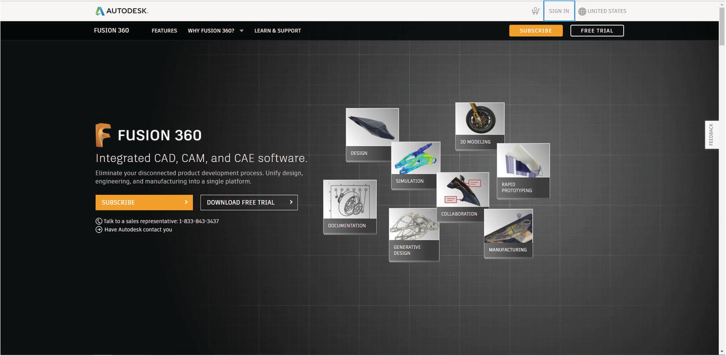
Click the SIGN IN link

SIGN IN drop-down menu
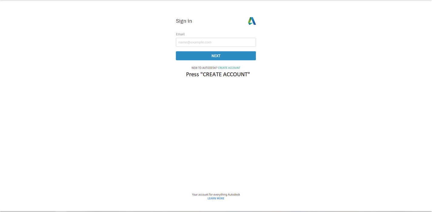
Autodesk login screen
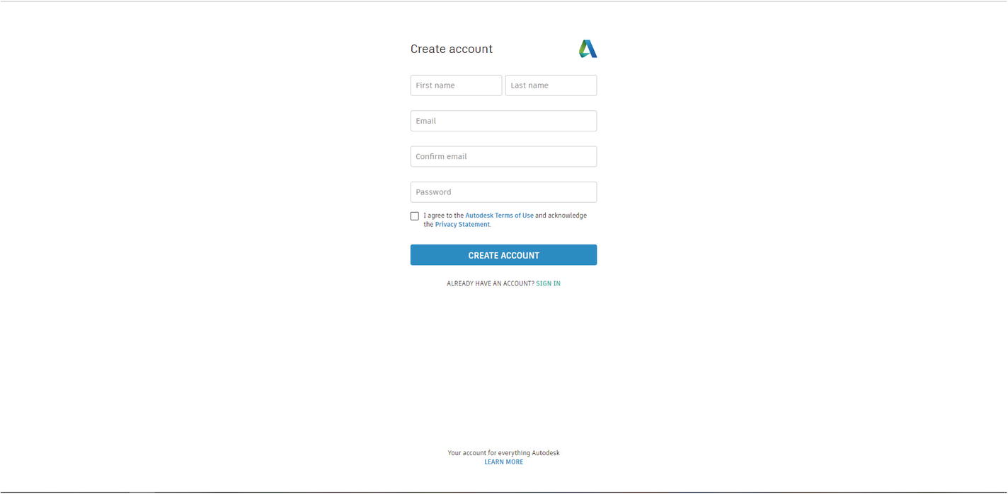
Click the “CREATE ACCOUNT” button
After that, click the “CREATE ACCOUNT” button. This will then send you an email asking you to verify your account; click the “VERIFY EMAIL” button in the email you received from Autodesk, which will bring you back to Autodesk and tell you whether you were successful or not.

Click the “FREE TRIAL” link

Click the “NON-COMMERCIAL USE” link
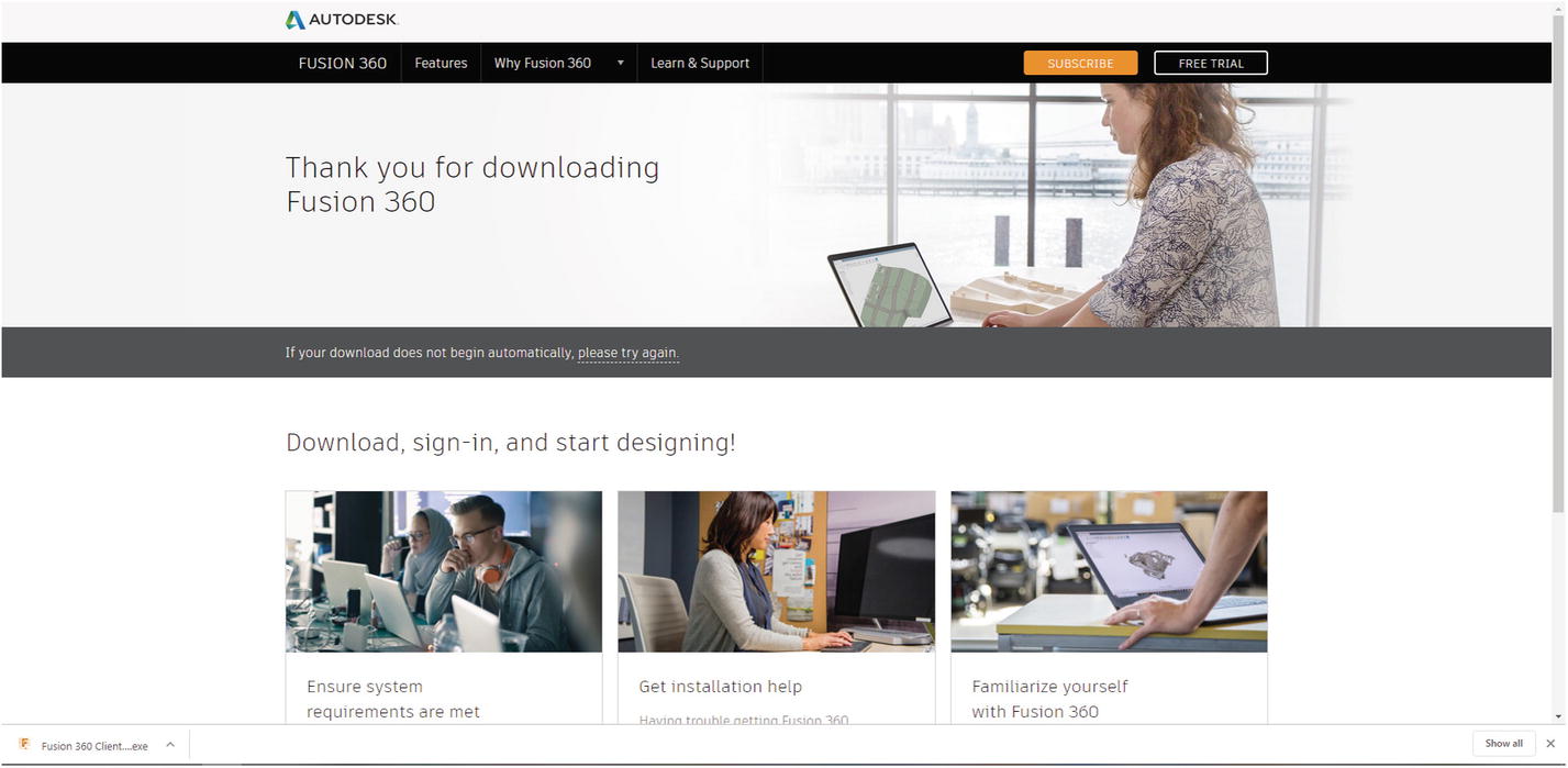
Fusion 360 will begin to download
Now that the download is completed, you will need to install Fusion 360 which will be discussed in the next section.
Installation Procedures for Fusion 360
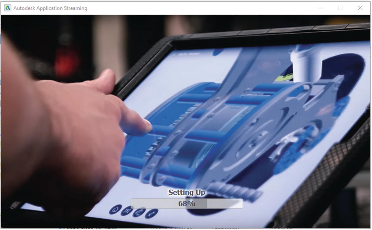
Install Fusion 360

When Fusion 360 is done installing, sign in and the main screen will appear
Once that is done, Fusion 360 should start up automatically. You may notice a lot of buttons and menus on the screen now; these will be discussed in the next section.
Getting to Know Fusion 360
Before we get into designing 3D objects in Fusion 360, it is important to know the various interfaces/controls that you will be using in order to manipulate your models. This section will go over several areas in Fusion 360; it won’t be a complete reference to Fusion 360 as that could be and has been the talk of many books, but it will get you started, so that you can begin to work with Fusion 360.
Fusion 360’s User Interface
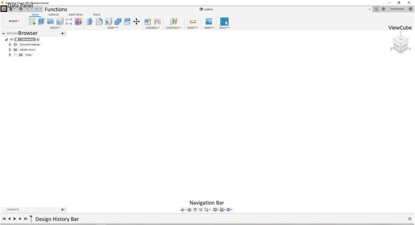
Layout of Fusion 360
Let’s first talk about the mouse gestures you will need in order to maneuver around in Fusion 360.

Right mouse click

Make selection with left mouse click and drag top left to bottom right

Only lines completely in the window will be selected
Make selection with left mouse click and drag top right to bottom left
Will select entire shape
Center mouse button: Usually, the wheel on the mouse is also a center mouse button; when you click this in Fusion 360, you can pan the object. This will be denoted by this ![]() pointer image.
pointer image.
Mouse roller: Use this to zoom in and out of an object. Roll forward to zoom in and roll backward to zoom out.
Now that that is over, we can start to talk about the many menus and icons on the Fusion 360. Let’s start with the ViewCube.
ViewCube: This visual aid is located in the top-right corner of the screen and will show you the current view of the object or plane; you can select Top, Bottom, Front, Back, Right, and Left, and the view will switch immediately to the selected view. Also, you will see arrows that allow you to turn the object clockwise or counterclockwise. Then there is a Home button that will take you to the Top-Front-Right corner of the object or plane. Finally, there is a drop-down menu that will allow you to change how you see your objects, and you can also set a new home for the 3D object. See Figure 3-16.

ViewCube
Browser: This menu will allow you to create a new component which will have sketches and bodies that can be manipulated. Also, the planes are located here under the Origin submenu and if selected will display a demo of the plane. The final thing I want to say about the Browser menu is that under the Document Settings submenu, you will find the Units control which will allow you to switch from inches to millimeters or vice versa. This will be used throughout this book, so you will get plenty of practice with navigating its options. See Figure 3-17.
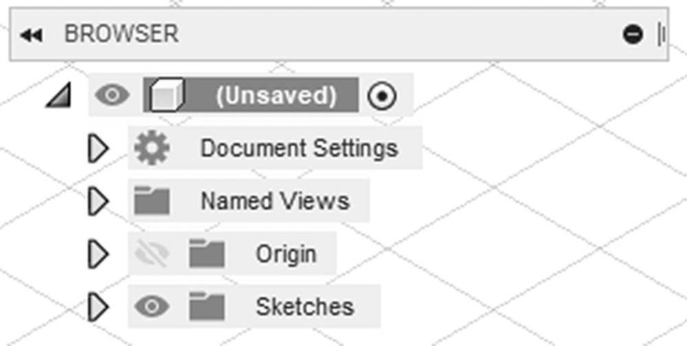
Browser
Design History Bar: This is very important when it comes to parametric 3D Modeling as this will allow you to move back and forth from one feature to the next. For example, say you want to modify a sketch at the very beginning of a component and you also want the features that you have done to also apply to these new dimensions; you would use the Design History Bar to move back to that sketch, modify the dimensions needed, and then move the bar back to the last feature, and that’s it! The model will use those new dimensions and apply all the features you have already created. You can also move features and sketches around and delete features as needed. See Figure 3-18.

Design History Bar
- Navigation Bar: Instead of using the mouse, you can use this menu to select ways to move around a component or sketch. The selections are
Orbit: Allows you to rotate around a component
Look At: Select a face or sketch, and the view will be switched to that face.
Pan: When this is selected, hold the left mouse button and move the mouse to view an object in the left, right, up, and down directions.
Zoom: When selected, zooms in and out of a component.
Zoom Window: This will allow you to zoom in to a region of a component or sketch.
Display Settings: This allows you to change effects, environment, visual style, object visibility, and so on; the most used feature here is the visual style which will allow you to change to a wireframe to see hard-to-see areas of a component.
Grid and Snaps: Allows you to change where components or sketches snap to; initially, this is set to 10mm, which is what we will use for this book.
Viewports: This will allow you to see a component from multiple angles.
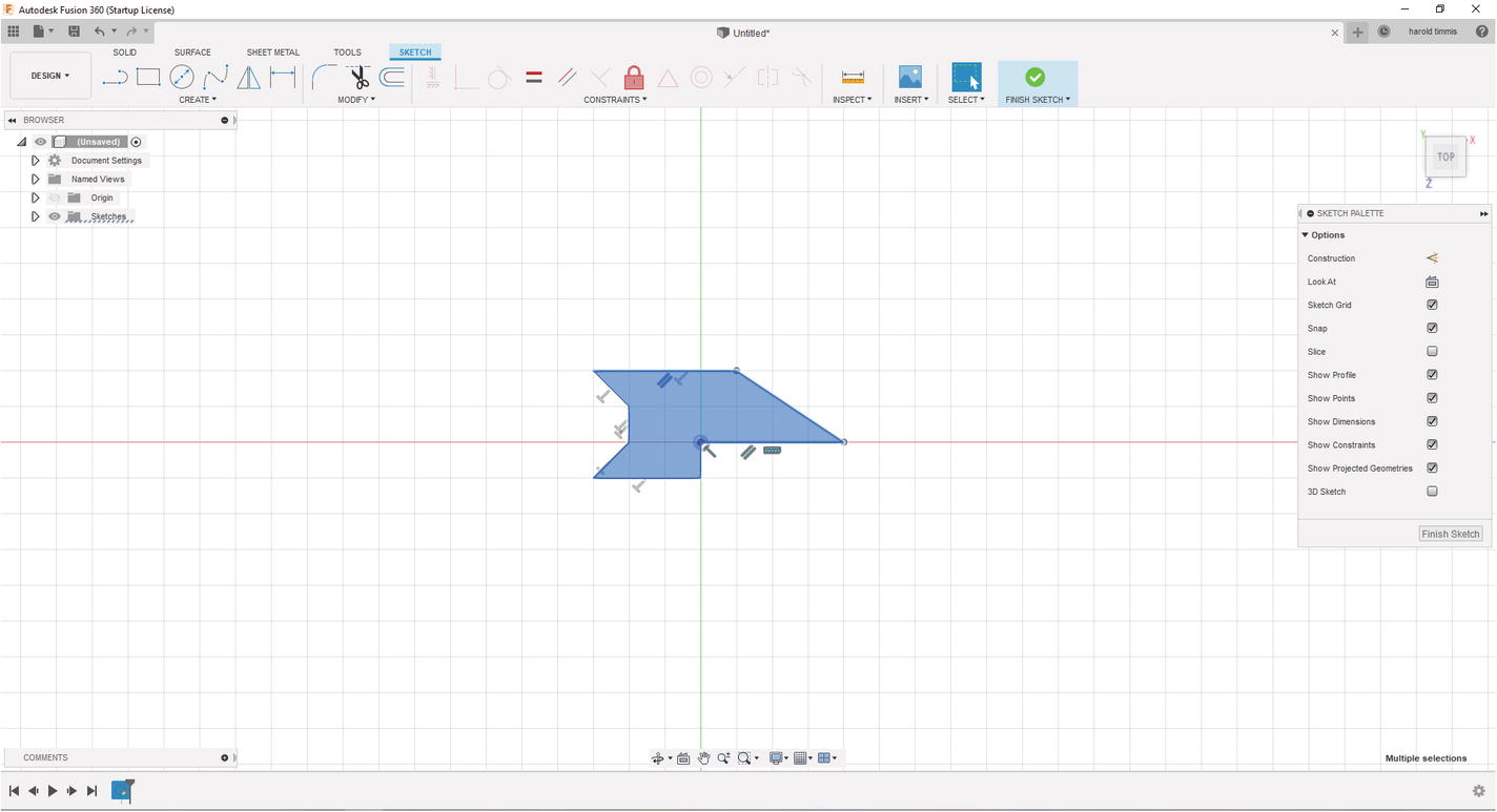
Fusion 360 Sketch Tools
Now we can get down to the nitty-gritty of parametric design. By using sketches and sketch features, we can create a 2D model that can be extruded, revolved, loft, and so on to create a 3D object, so that later on if we need to make changes to the model, we only need to change the dimensions on the sketch. For now, we will go over the basics and move to more sophisticated tools in later chapters.
Create Sketch: This is the first thing you will do after making/naming components needed for the model. This will put you into sketch mode automatically, and the only thing you need to do to begin drawing is to select a plane.

Line: This allows you to create a line on the plane you selected; just left-click where you want the line to start and then left-click again to select where you want the line to end. Later, we will use the dimensioning tool to constrain our sketches. Equally important to note is that there are two types of line; one is a regular line, and the other is a construction line. A construction line will not be a part of your overall sketch, and because of that when you extrude your sketch, the dimensions of the construction lines will not be included. To turn a line into a construction line, select the line and press the “x” key on your keyboard. See Figure 3-19 for an example of a normal line and a construction line.
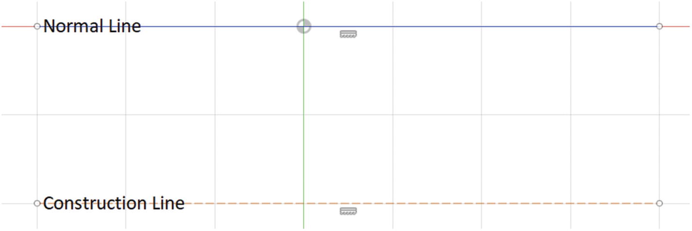
Normal and construction lines

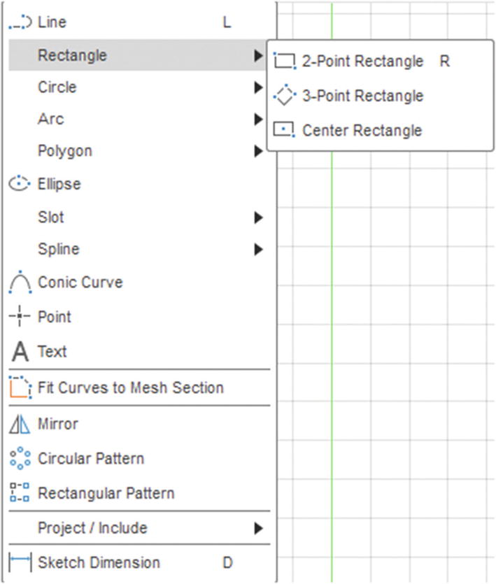
Rectangle: There are a few types of rectangles, and each one has its benefits in certain situations; we will be going over these different benefits later in this book. For now, it is important to know the center rectangle which will create a rectangle from the inside out. The other rectangle is the two-point rectangle; this will allow you to select two points in a plane that will create a length and width for a rectangle.
Circle: There are several options here; for the most part, we will stick with the center diameter circle which, just like the center rectangle, will create a circle from the inside out.

Arc: Mainly, we will be using the three-point arc which will create an arc based on three individual points.

Polygon: Create a specific number of sides sketch, for example, a hexagon.

Text: This is a great feature for adding text sketches onto your models, which just recently became available.

Mirror: This is a great time savings tool; it allows you to duplicate lines from one side of a centerline to the other side, so you will only need to create half a sketch if the sketch is symmetric.

Fillet: This will create an arc with a specific radius. All you must do is select two coincident lines like a corner of a rectangle.

Trim: This is a very useful tool when you need to clean up your sketch by trimming lines that are not needed, but be careful if those lines are used to constrain your sketch; you might be better off making them a construction line.
Offset: To use this feature, select the outline/lines you want to offset and then put in the dimensions needed; you should then see a demo of what to expect when you accept the offset. This is a great time saver if you need to, for example, make a small border around a sketch or object.

This should be enough to get started with as we will be using most of these functions throughout this book, but don’t be discouraged; I will be introducing more features in later projects. This is just a good set of features to start with.
Fusion 360 3D Tools
Alright, now once you finish creating your sketch, you will need tools to make a 2D image a 3D object. This can be done several ways in Fusion 360; we will discuss a few of them in this section, as well as a few features that will allow you to modify a 3D object without using the sketch.
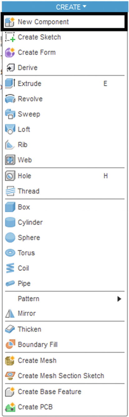
New Component: This is used when you first start to make your model. You should separate your 3D project into several components if it is required, which most of the time it is. Also, give the component a well-defined name, so that you know what that component’s 3D model is; you do this by going to the Browser menu on Fusion 360 (see the “Getting to Know Fusion 360” section) and double-clicking the new component and renaming it.
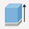
Extrude: Probably the most used method of going from a 2D sketch to a 3D object. This will allow you to extrude a sketch to a desired height. There are also other settings here that will allow you to extrude to another 3D object surface; also, if you want to make a hole, you can extrude into a 3D object, and it will cut out material instead of adding it.
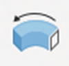
Revolve: This will allow you to select a sketch and revolve it around an axis. Very useful when you want to make a cylindrical object.
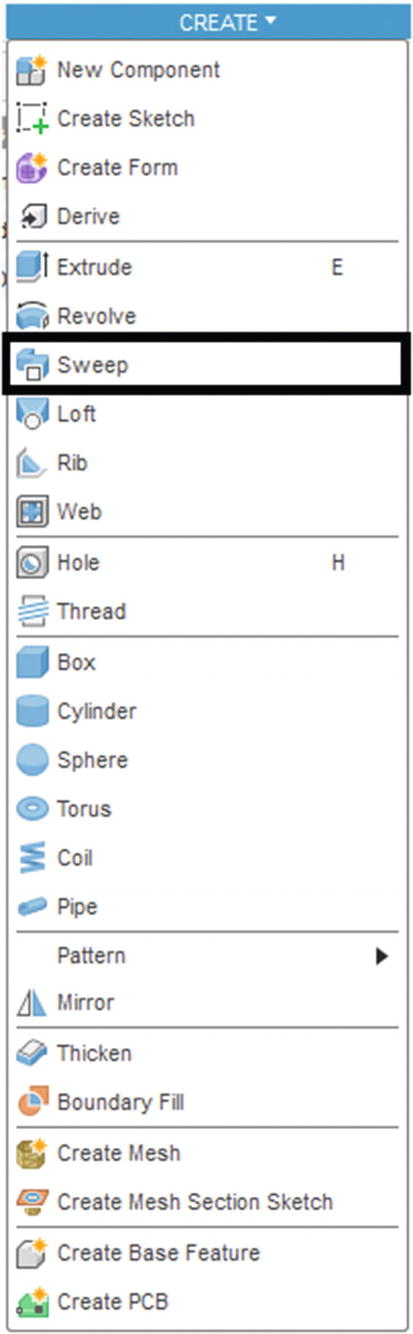
Sweep: Create a 3D object by selecting a sketch and a path (a line) for the sketch to follow.
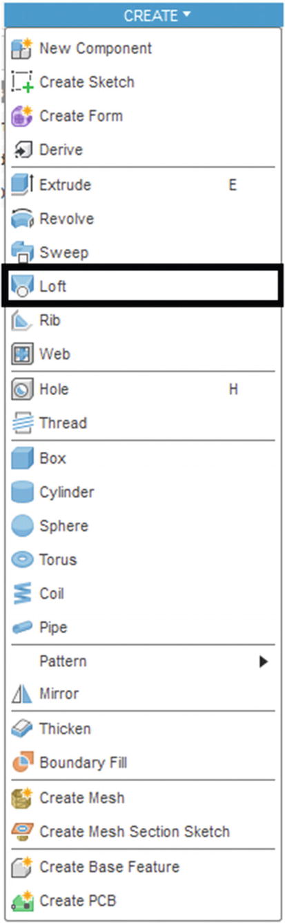
Loft: Create a 3D object by selecting multiple sketches on multiple planes; this will then create a 3D object with those shapes as profile.
Rectangular Pattern: Just like in the sketch mode, you can create patterns that will allow you to quickly replicate 3D objects; this also works for holes. This function creates a rectangular pattern. You can also choose how many objects are replicated, which axis to create the sketches on, and what type of pattern to create.

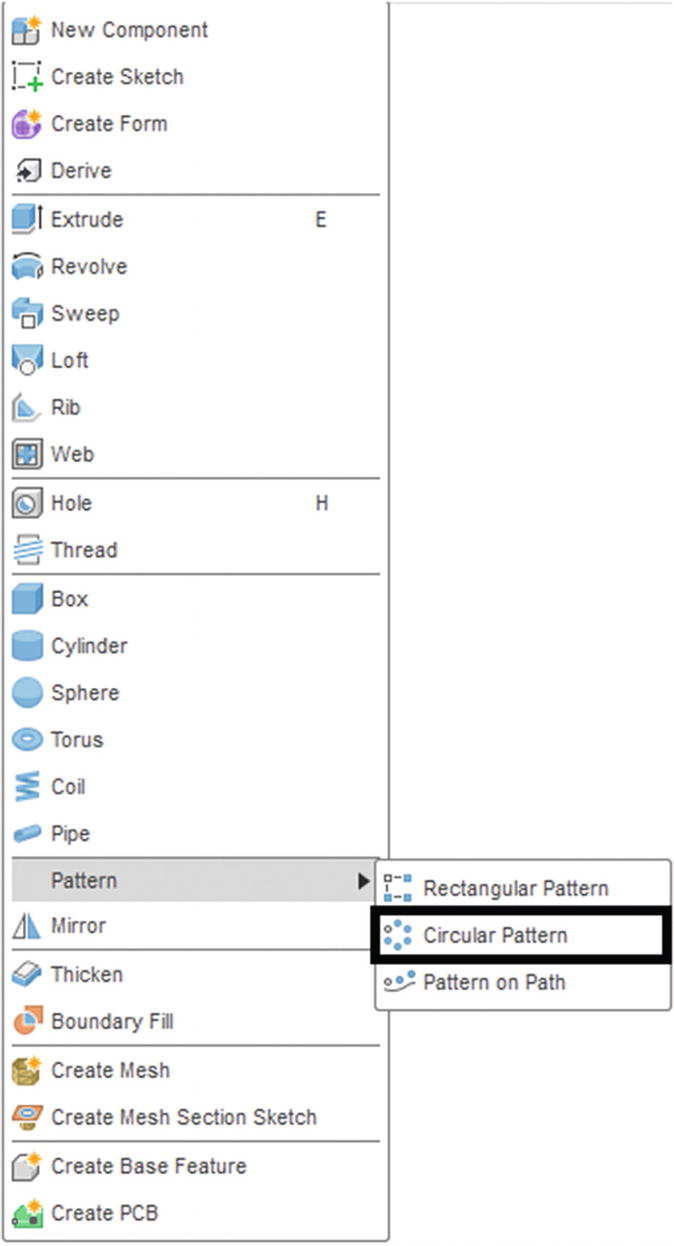
Circular Pattern: Just like in the sketch mode, you can create patterns that will allow you to quickly replicate 3D objects; this also works for holes. This function creates a circular pattern. You can also choose how many objects are replicated, which axis to revolve around, and what type of pattern to create.
Press Pull: This will allow you to extend a face or retract a face. Useful if you need to make a quick modification to a face.
Fillet: Adds a radius to one or more edges. This can be used to strengthen corners by adding a bit more material between two faces.
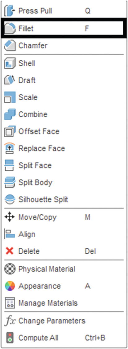
Chamfer: Will create a bevel on one or more edges. This can be used just like the fillet; it will create an angled feature as opposed to a round feature.

Shell: This tool is very useful if you need to make a hollow object. All you need to do is select the face to shell and then specify the inside thickness and voila! You have a hollow object.

Combine: If you need to merge two or more objects, this tool will allow you to do that.

Well, I know this might all seem like a lot, but with a little practice and patience, you will be able to create a lot of different models even with this short list of functions. Next up! I will explain a few tools that you can use to measure and review your models.
Fusion 360 Tools
There are a lot of useful functions in the Tools tab; they can be used for many things like checking out a section of a model or measuring distances between two or more points. You will want to get used to using these as it will be important later when you are making your own models or working on someone else’s model. Here is a short list of Fusion 360 tools:
Measure: Measure the distance, angle, and area of two points.
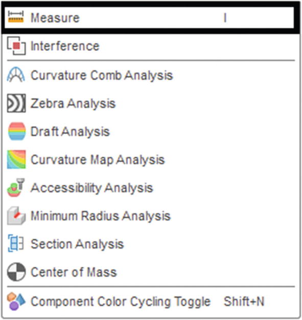
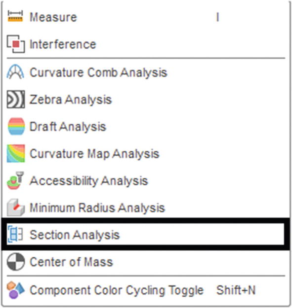
Section Analysis: Allows you to see your object in a cutaway view; you can move the arrow to view different areas of an object. For example, say you have a hollow box and you want to make sure there are no other structures within the hollow box; you can use this feature to look inside the box and verify no other structures are in it.
Alright, that was short and right to the point. There are many other tools in this menu, but for starters these are the key tools, so I wanted to go over them first. The final portion of this section will go over how to import various files into Fusion 360.
Importing Files
Sometimes , you may need to import a STEP file, a DXF file, or maybe even an SVG file. Here are some functions that will help make adding these files possible:
- 1.
Go to the Data Panel by clicking the Data Panel button at the top left of the screen. See Figure 3-20.

Select Data Panel
- 2.
Select New Project. See Figure 3-21.

Select New Project
- 3.
Name the project.
- 4.
Click the “Upload” button. See Figure 3-22.

Select Upload
- 5.
A pop-up window will appear, and you can drag and drop or select the STEP file you want to use in this project. See Figure 3-23.
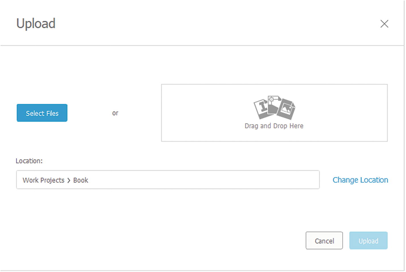
Drag and drop the STEP file or browse to the file
- 6.
Click the Upload button, and you will see this screen which will tell you the progress of your import. When the STEP file is finished, click the “Close” button. See Figure 3-24.
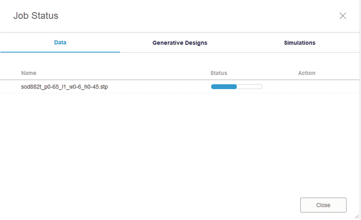
When finished, click the Close button
- 1.
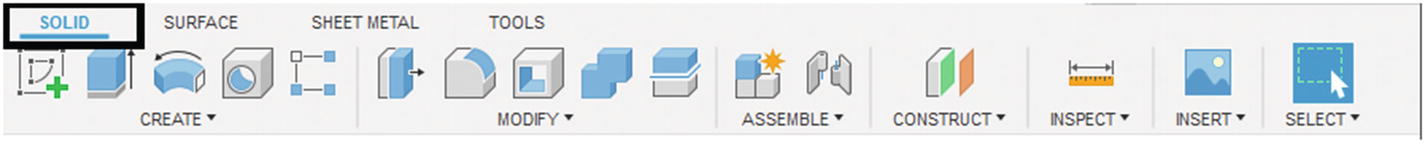
Go to the “SOLID” tab in Fusion 360. See Figure 3-25.

Go to the “SOLID” tab
- 2.
Go to the “INSERT” drop-down menu. See Figure 3-26.

Click the “INSERT” drop-down menu
- 3.
Select the “Insert DXF” option. See Figure 3-27.
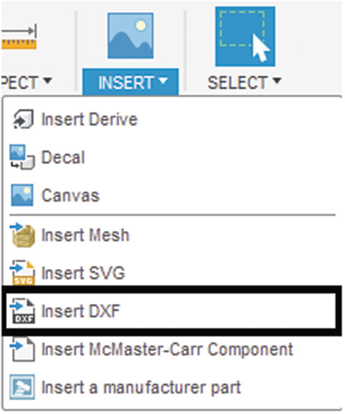
Click the “Insert DXF” button
- 4.
Select the plane/sketch that you want the DXF image to be placed on to. See Figure 3-28.
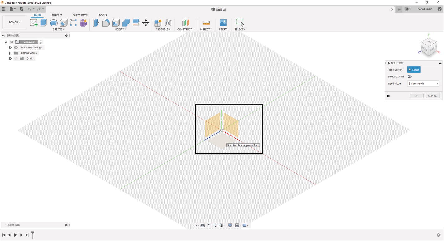
Select the plane that the DXF will display on
- 5.
Select the DXF file. See Figure 3-29.

Select the DXF file from your computer
- 6.
Then click the “OK” button. See Figure 3-30.

Click the “OK” button
- 7.
You should now see your DXF file on the plane you chose earlier. See Figure 3-31.

DXF is loaded into Fusion 360
- 1.
Go to the “SOLID” tab in Fusion 360. See Figure 3-32.
Go to the “SOLID” tab
- 2.
Go to the “INSERT” drop-down menu. See Figure 3-33.
Click the “INSERT” drop-down menu
- 3.
Select the “Insert SVG” option. See Figure 3-34.

Click the “Insert SVG” button
- 4.
Select the plane that you want the SVG image to be placed on to. See Figure 3-35.
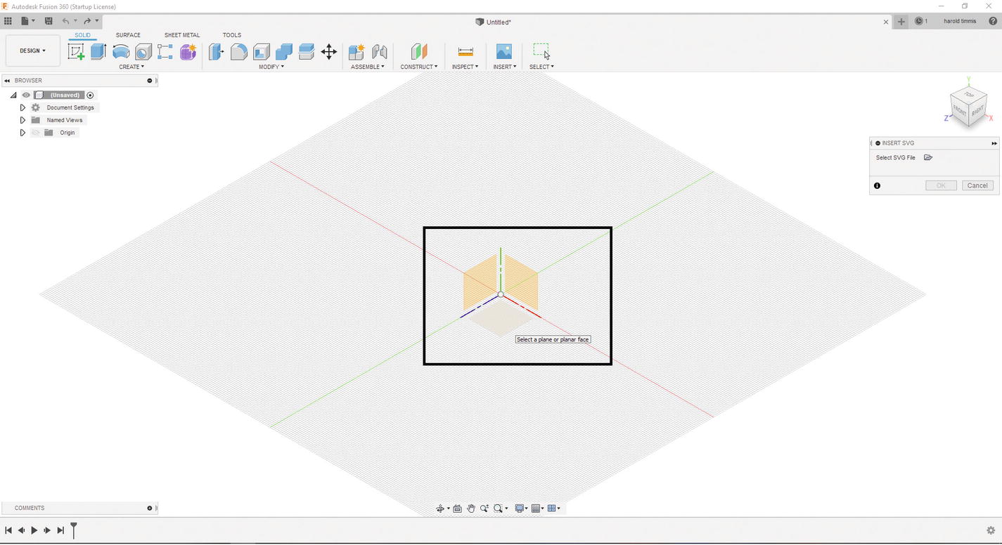
Select plane
- 5.
Select the SVG file. See Figure 3-36.

Select the SVG file from your computer
- 6.
Then click the “OK” button. See Figure 3-37.
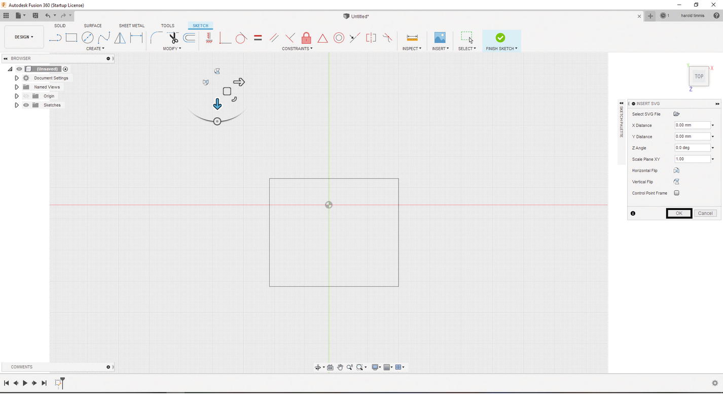
SVG will be added to Fusion 360
- 7.
You should now see your SVG file on the plane you chose earlier. See Figure 3-38.

SVG is ready to be extruded
Alright, now that you have a little understanding of Fusion 360, you can move on to the exciting part, making your first 3D model. After reading through this chapter, you may feel you are not ready to make a model yet, but don’t worry; it won’t be that complicated, and you can always look back if you need to know where a function is, so without further ado let’s get modeling!
Your First 3D Model in Fusion 360
Alright, let’s get started with a simple 3D model, and then we will move to a more complex 3D model (don’t worry; it won’t be too complex). Go ahead and open Fusion 360 so we can create our first sketch.
Creating a Sketch
- 1.
Save this project as “Cube” by pressing Ctrl-S.
- 2.
Click the “Create Sketch” icon under the “SOLID” tab. See Figure 3-39.

Left-click “CREATE SKETCH”
- 3.
Select a plane to draw your sketch on. In this example, I chose the XZ plane. See Figure 3-40.

Select plane from the grid or the Browser menu
- 4.
Now select the Rectangle tool under the “SKETCH” tab. See Figure 3-41.
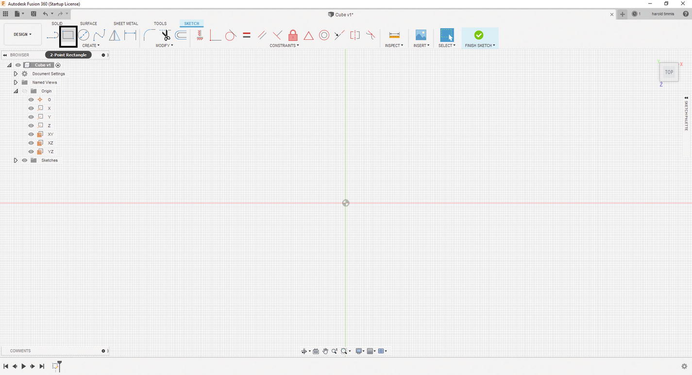
Select a two-point rectangle from the “SKETCH” tab
- 5.
Put a rectangle anywhere on the grid; don’t worry about the dimensions yet. Press “Enter” when you are finished. See Figure 3-42.
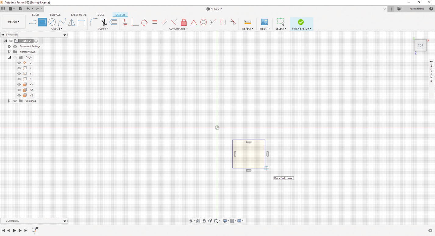
Add a rectangle to the grid
- 6.
Click a single point of your sketch and the origin. See Figure 3-43.
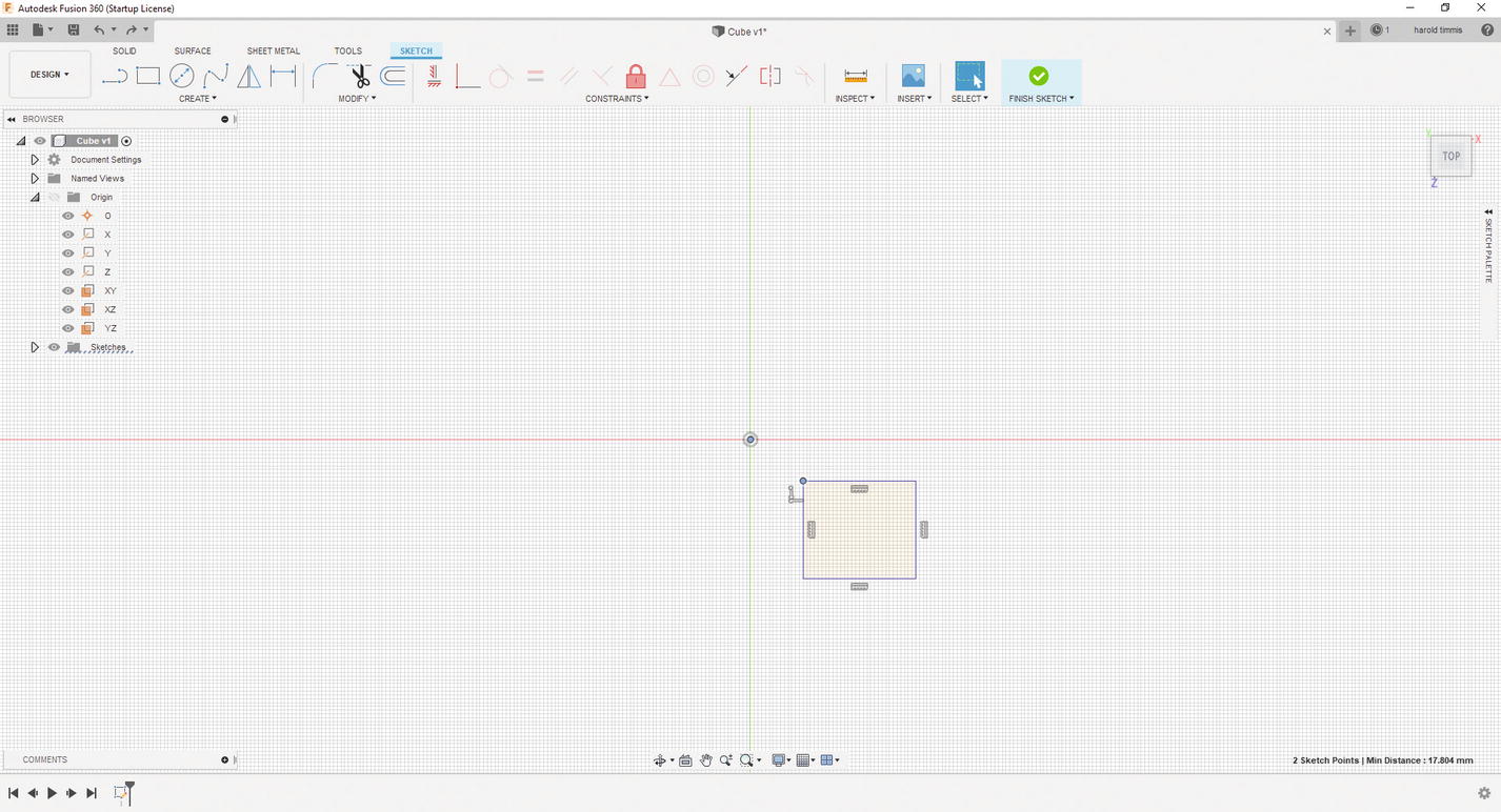
Left-click a single point on the rectangle and a point on the origin
- 7.
Go to the “CONSTRAINTS” menu under the “SKETCH” tab. See Figure 3-44.
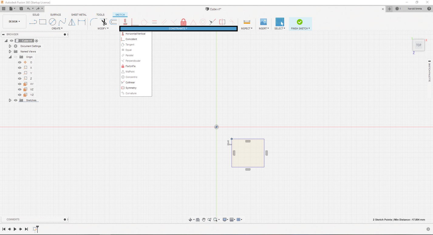
Select the “CONSTRAINT” drop-down menu
- 8.
Select the “Coincident” selection, then select the origin, and you will notice that your square has moved to the origin and two of the four sides of your square have turned black which indicates those sides are now constrained. See Figure 3-45.

Select Coincident from the drop-down menu
- 9.
Now let’s constrain the other two sides. Press the “D” key. Select one of the blue sides and enter the value 5. (I am using millimeters; this can be switched in the Browser menu under Document Setting ➤ Units). Now three sides are constrained. See Figure 3-46.
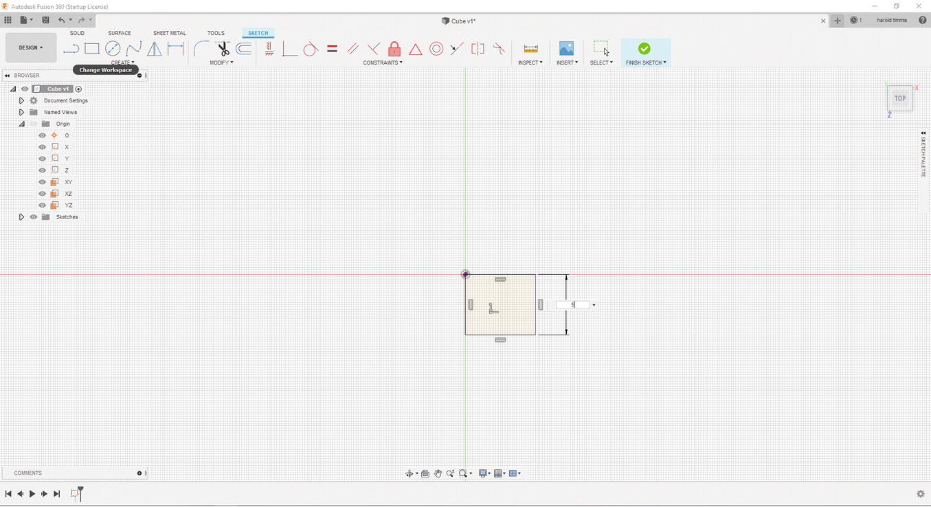
Add dimensions for one side of the rectangle
- 10.
Finally, let’s constrain the last side by pressing the “D” key and selecting the final blue side and entering a 5 into the text box. See Figure 3-47. Congratulations! Your sketch is fully constrained now.
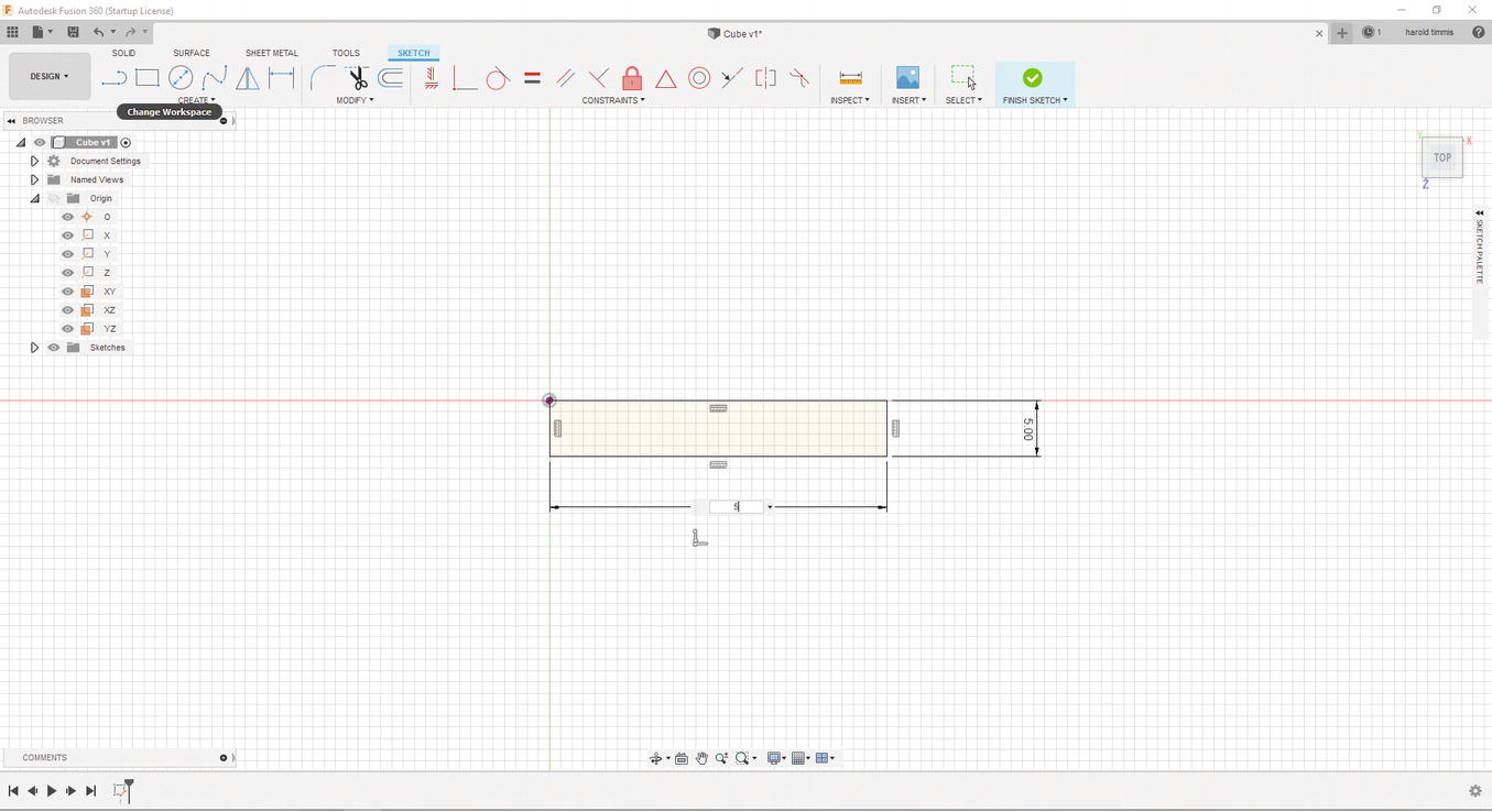
Add dimensions to the last side of the rectangle
- 11.
Select the “FINISH SKETCH” button to get out of sketch mode. See Figure 3-48.

Click “FINISH SKETCH”
Okay, now that the sketch is done, you can move on to the next part which will have you create a 3D model from the sketch you just completed.
Using the Extrude Function
- 1.
Select the “Extrude” function from the “SOLID” tab. See Figure 3-49 .

Select the Extrude function
- 2.
The “Extrude” function has a lot of options, but for now let’s just move to the distance text box and enter “5” and press enter. See Figure 3-50.
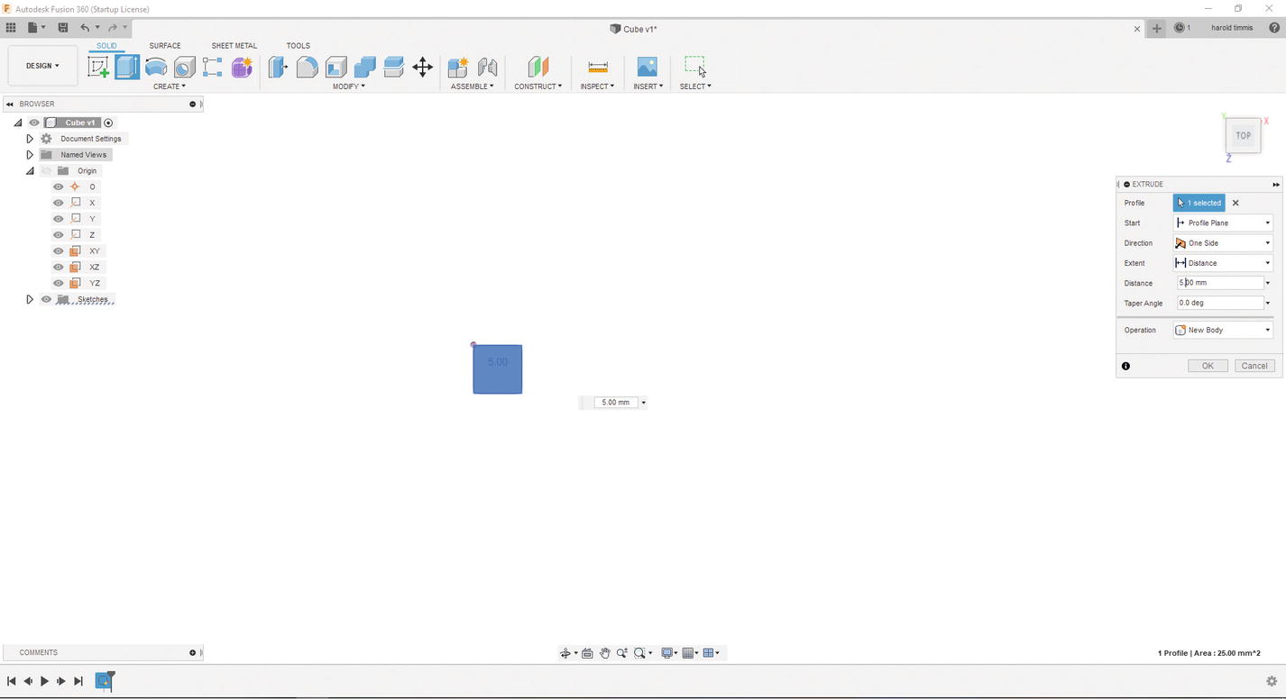
Extrude out 5mm
- 3.
You can get a better angle on the 3D model by pressing the Shift key and holding down your mouse’s center button and moving the mouse toward your computer screen. You could also select the “Home” button next to the ViewCube. See Figure 3-51.
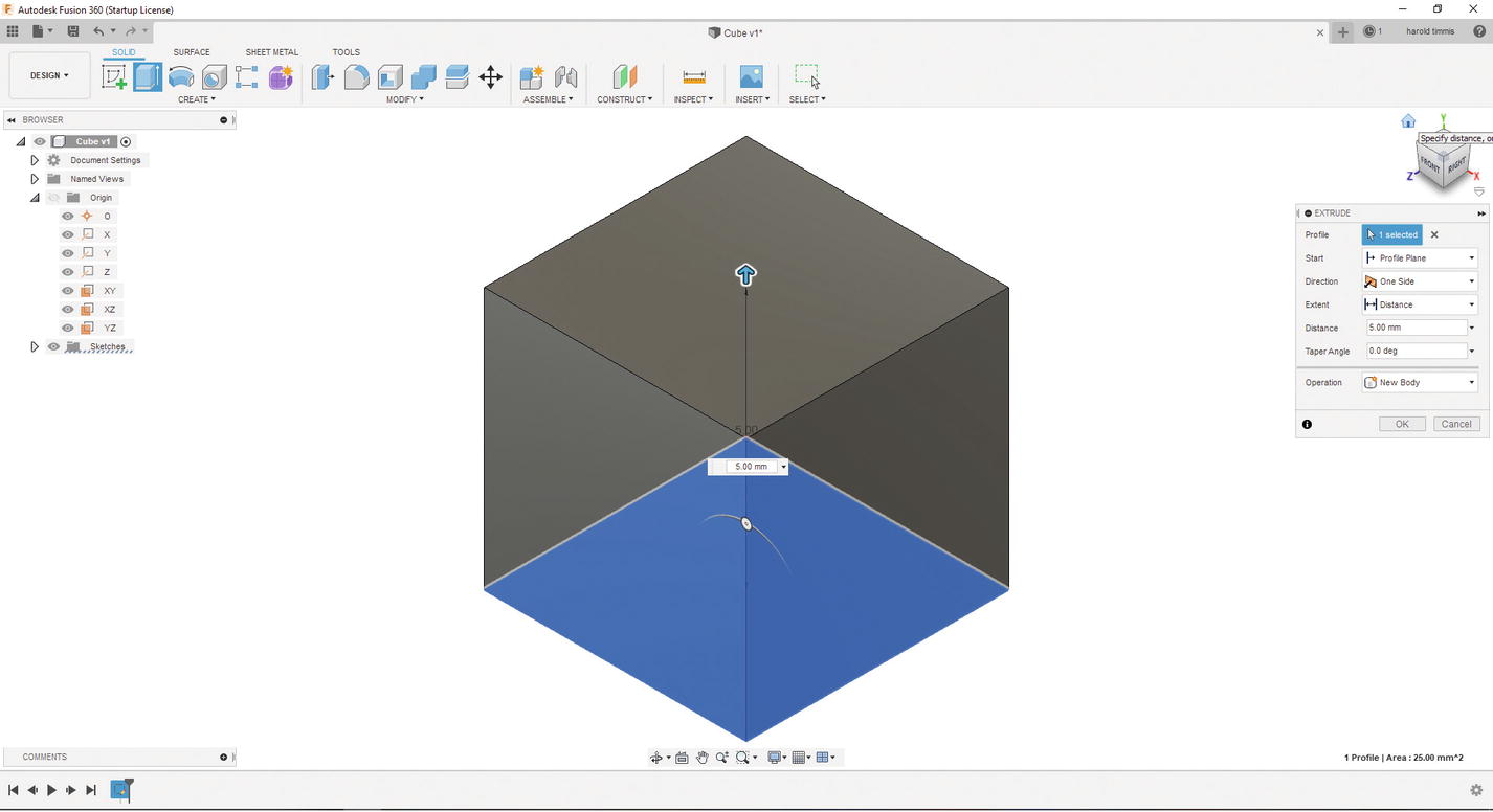
Select “HOME” on ViewCube
- 4.
If everything looks fine, press the Enter key or click the “OK” button under the “EXTRUDE” menu. See Figure 3-52.
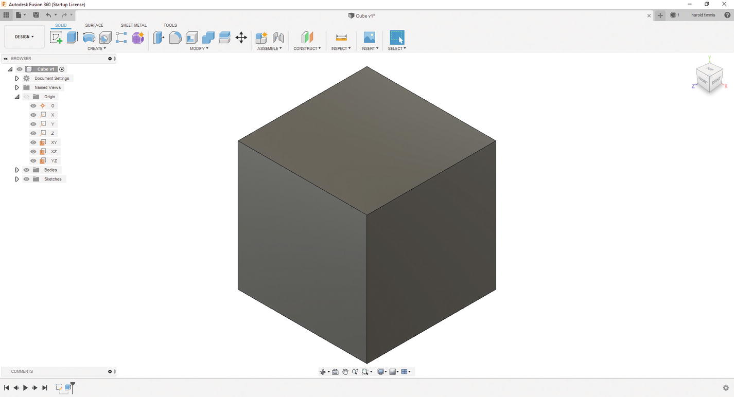
Final cube
Alright! That was your first 3D model. Great job! Now I want to move on to a bit of a more complex example that will be used in the following chapter. Also, it will be a good segue into parametric 3D Modeling as we will use the “Cube” project to make a keychain.
Parametric Modeling in Fusion 360
- 1.
Let’s start by opening our Cube project. Go to the Data Panel ➤ My Recent Data; the Cube project should be the most recent project. See Figure 3-53.

Go back to the Cube project
- 2.
Double-click the Cube project and close the Data Panel.
- 3.
Go to the Browser menu and go to the folder Sketches and double-click Sketch1. This will take you to the Sketch view, and you can start to modify your sketch. See Figure 3-54.

Select Sketch1
- 4.
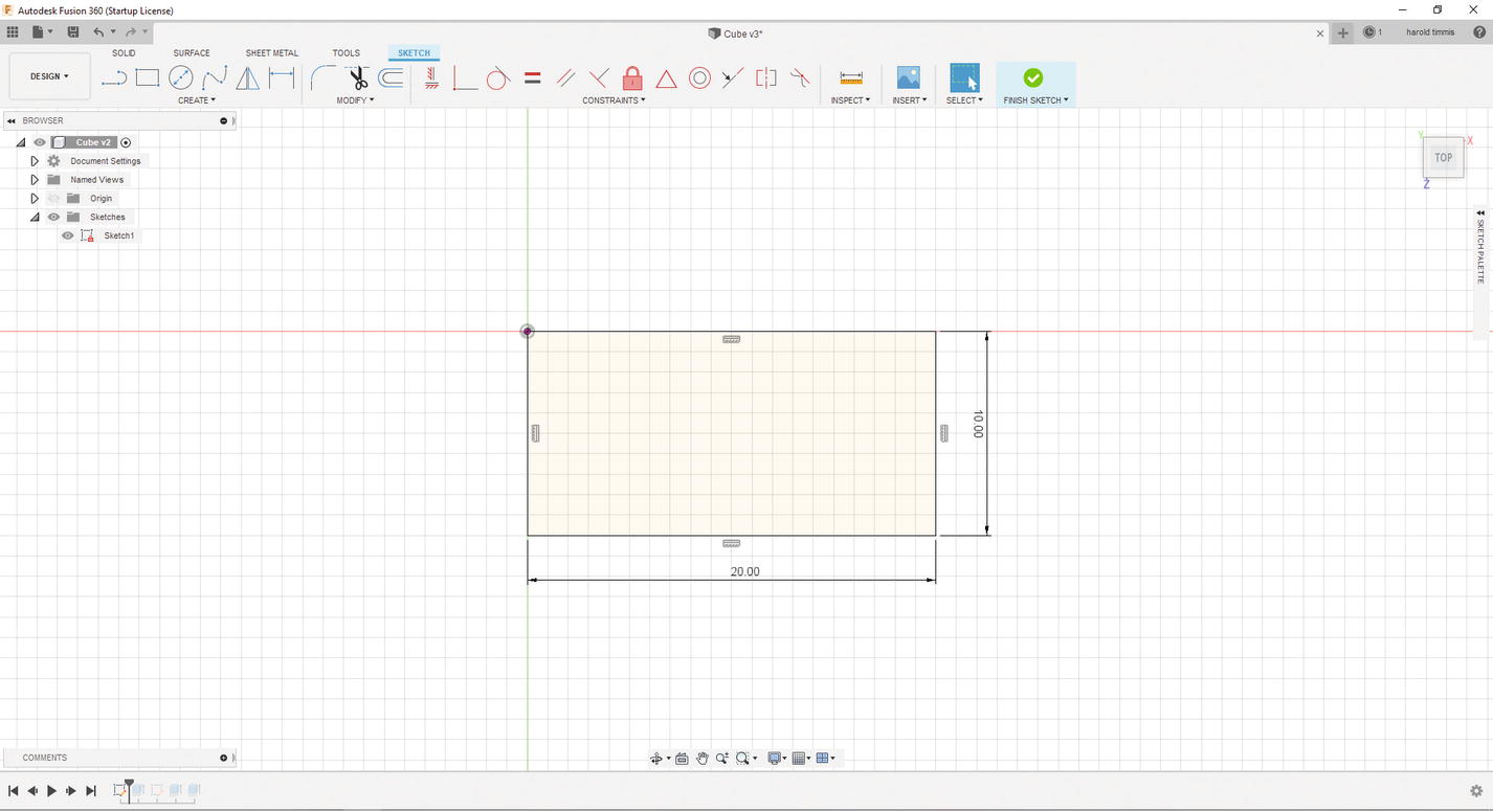
We want to change this square into a rectangle; let’s change (double left-click) the X axis dimension to 20mm and the Z dimension to 10mm. To do this, press the “D” key and select the X axis dimension and type in 20mm, then change the Z dimension to 10mm. Press “Enter” when you are finished. See Figure 3-55.
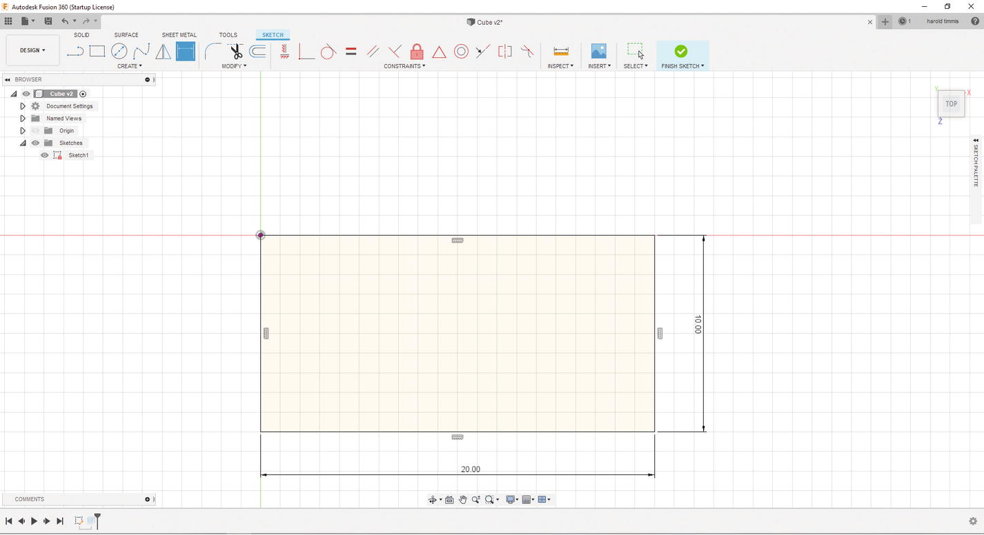
Change dimensions for the X and Z axis
- 5.
Click the “FINISH SKETCH” button. See Figure 3-56.
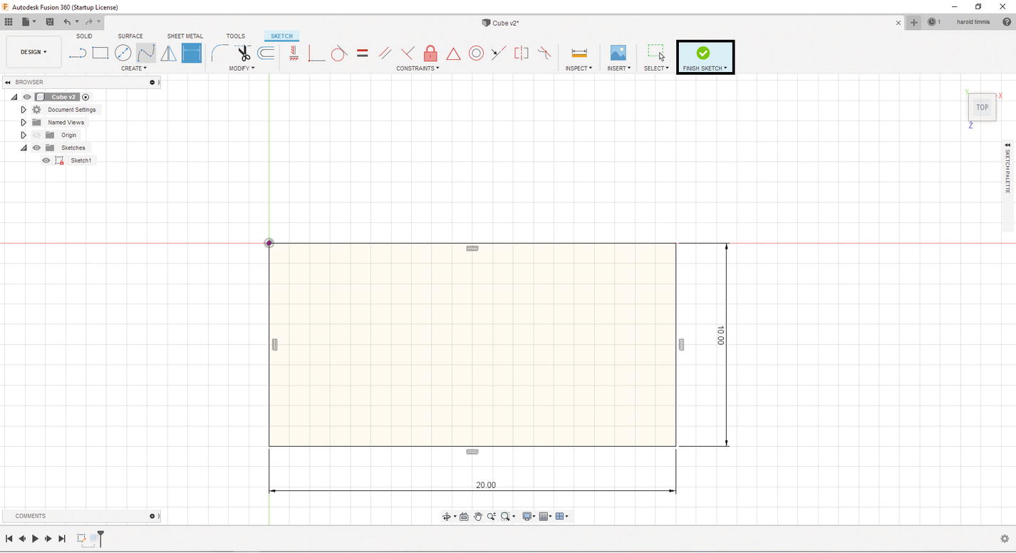
Click the “FINISH SKETCH” button
- 6.
You will notice that your 3D model has changed to a shape that is 10mm x 20mm x 5mm. This is the power of parametric 3D Modeling; it allows you to make quick changes to your sketch and then applies these dimensions through the rest of the history of the 3D object.
- 7.
Now double-click the Extrude1 icon in the History Bar at the bottom of the screen. See Figure 3-57.
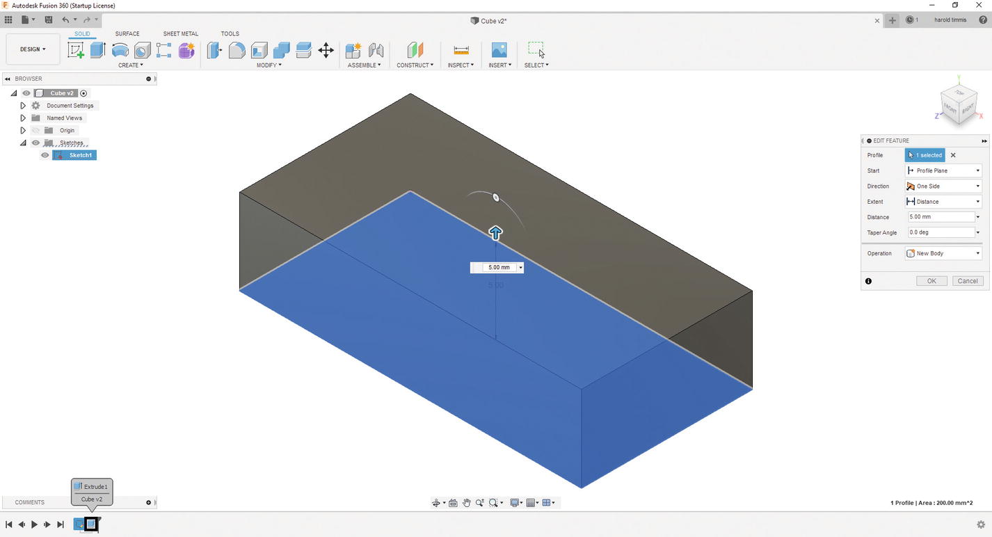
Select the Extrude1 in the Design History Bar
- 8.
Edit this to be 3mm instead of 5mm in the Distance text box and press enter. See Figure 3-58.
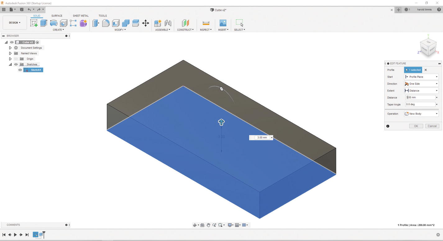
Extrude only 3mm
- 9.
Click the “Create Sketch” button at the top left under the “SOLID” tab.
- 10.
Select the top of the 3D object, and this will put you into sketch mode. See Figure 3-59.

Select the top of the 3D object
- 11.
Under the Create menu, select the Offset function and click the edge of the 3D object. See Figure 3-60.
Select the Offset function
- 12.
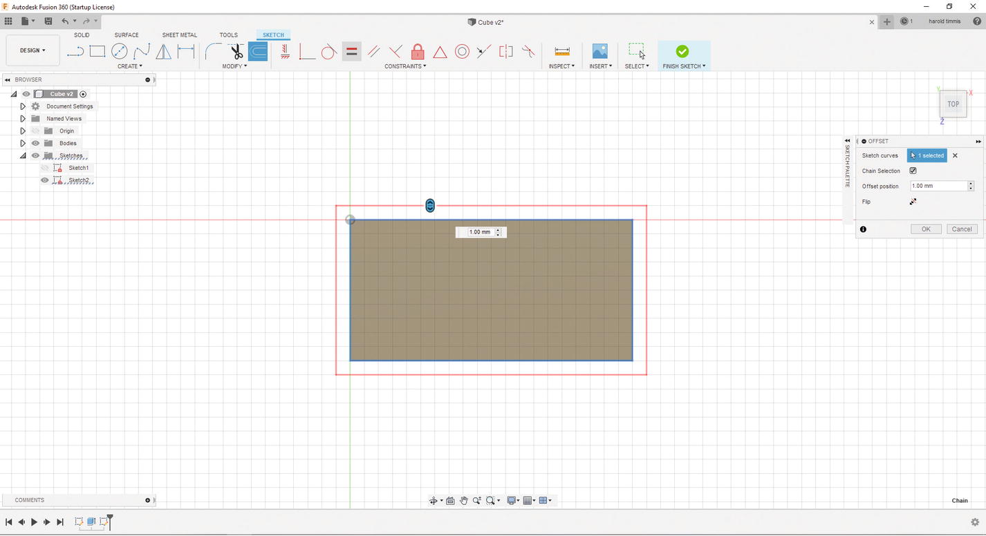
Notice that there is now a box around your 3D object. To change this, put –1.00mm into the Offset position text box, or just click the “Flip image.” Press “Enter” when you are finished. See Figure 3-61.

Edit the dimension to –1mm
- 13.
Click OK.
- 14.
Now select the Center Diameter Circle by going here: SKETCH ➤ CREATE ➤ Circle ➤ Center Diameter Circle, or just press the “C” key. See Figure 3-62.

Select the Center Diameter Circle
- 15.
Place a circle on the top face, just like the offset. See Figure 3-63.

Place a circle on the grid
- 16.
Now you will notice the circle is not constrained; let’s fix this. First, press the “D” key and select the circle’s edge; type in 3mm. Press “Enter” when you are finished. See Figure 3-64.

Add a dimension to the circle (3mm)
- 17.
Let’s make some construction lines, so that we know where the center of this rectangle is. First, select the Line function from the “CREATE” menu or press the “L” key, and place a line from one side of the rectangle to the other side. You will see this symbol
 when you have selected the center for an edge; once you see that, left-click and move to the other side and left-click again. See Figure 3-65.

Find the horizontal center of the rectangle
- 18.
Do the same for the top and bottom of the sketch. See Figure 3-66.

Find the vertical center of the rectangle
- 19.
Exit out of the Line function by pressing the “Esc” key.
- 20.
Select the two lines you created and press the “x” key. This will make both of those lines construction lines. See Figure 3-67.

Make both the horizontal and vertical center lines construction lines
- 21.
Now while pressing the “Ctrl” key, select the center of the circle and the horizontal construction line; then select the coincident constraint from the “CONSTRAINTS” menu. See Figure 3-68.
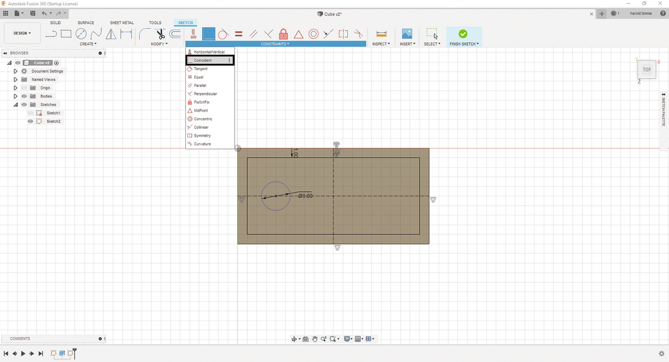
Constrain the circle to the horizontal center line
- 22.
Next, press the “D” key and select from the center of the circle to the edge of the left side of the vertical offset and put 3mm into the text field and press enter. See Figure 3-69.

Add the dimension from the left offset to the center of the circle to 3mm
- 23.
Now click the “FINISH SKETCH” button.
- 24.
Make sure you press Ctrl-S to save your progress.
- 25.
Now click the Extrude button on the “CREATE” menu and click the border area we created with the Offset function; extrude the border 1mm. Press “Enter” when you are finished. See Figure 3-70.
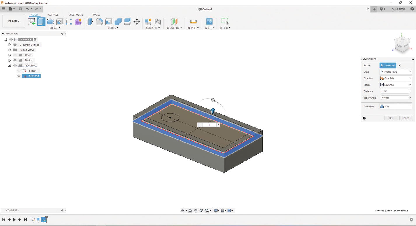
Extrude the border to 1mm
- 26.
Once you press the “Enter” key, the sketch goes away; to bring the sketch back up, all you need to do is go to the Browser menu and go to Sketches and click this button
 on Sketch2 to view the sketch. See Figure 3-71.

Show Sketch using the Browser menu
- 27.
Next, select the circle and click the Extrude button. This will be a bit different as you are going to create a hole. Rotate the 3D object so you can see the bottom of the 3D object and left-click the bottom of the 3D object and click OK; this will create a hole that is 3mm in diameter. Press “Enter” when you are finished. See Figure 3-72.
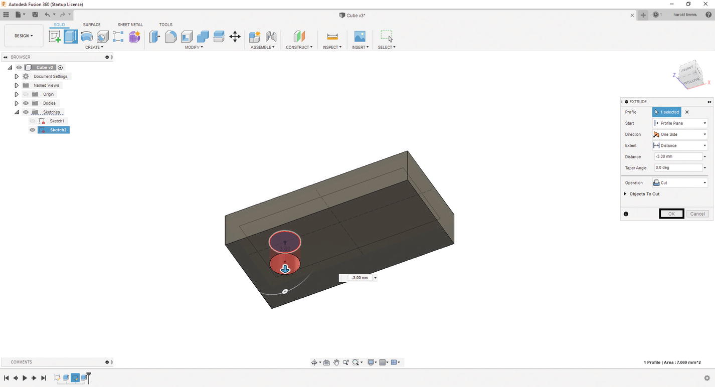
Extrude the circle to the bottom face
- 28.
You can hide your sketch again by clicking the same icon shown in step 26.
- 29.
Now to make this keychain template more appealing, let’s add a fillet to one side. Using the Design History Bar, move the slider right after the Sketch1. See Figure 3-73.

Go to Sketch1 in the Design History Bar
- 30.
Double-click the Sketch1 icon in the Design History Bar, and you will be able to edit this sketch. See Figure 3-74.
Select Sketch1
- 31.
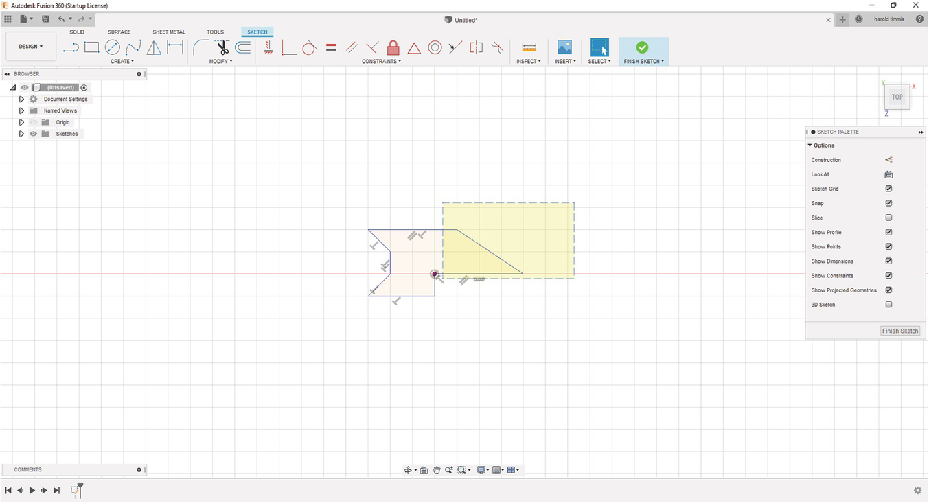
Add a fillet by going to the “MODIFY” tab and clicking the Fillet button. See Figure 3-75.
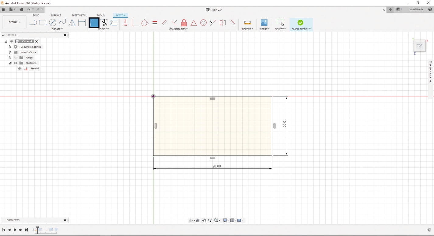
Add fillet
- 32.
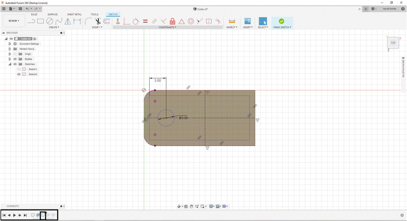
Click the top horizontal line, then the left vertical line, and finally the bottom horizontal line. See Figure 3-76.
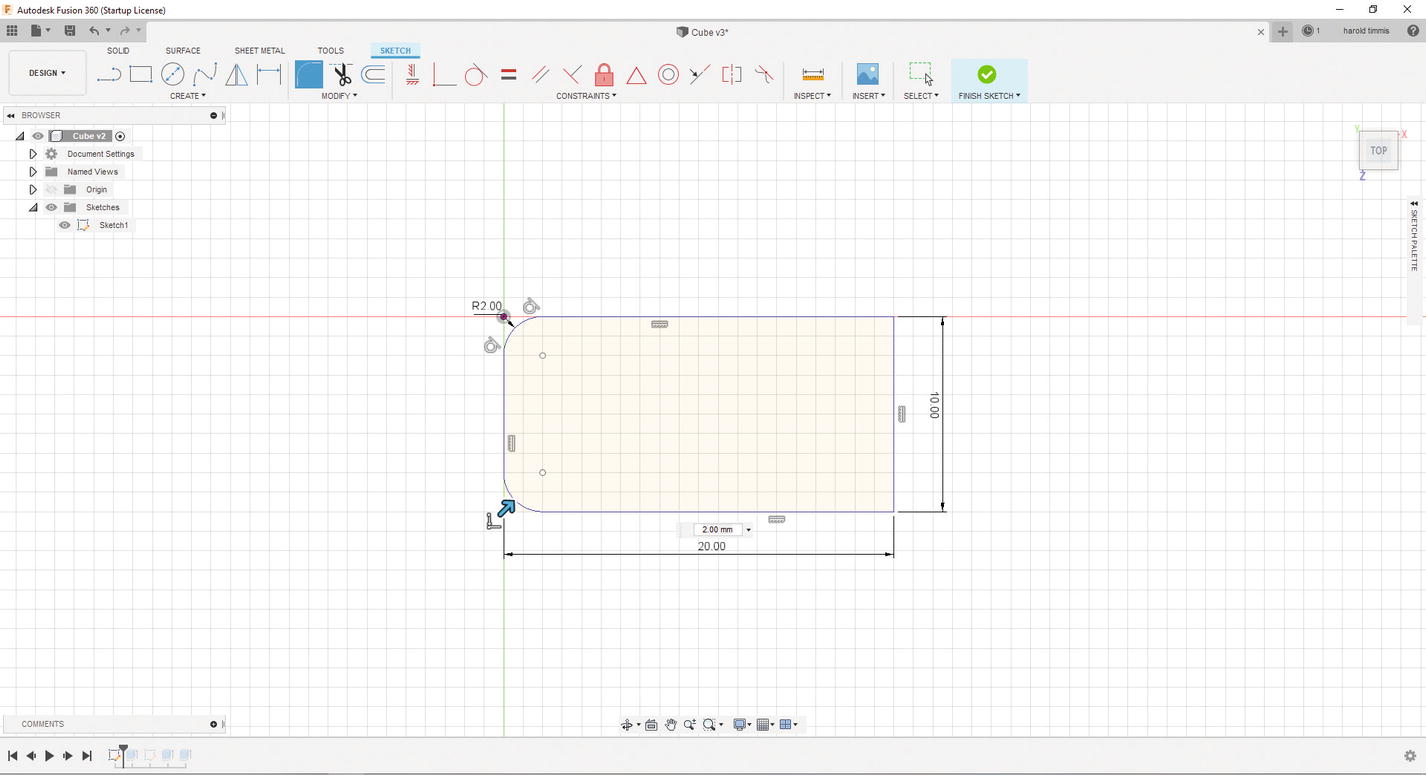
Select left-side outlines
- 33.
In the text box, put 2mm and press enter (don’t mind the warning that you may get when you do this). Press “Enter” when you are finished. See Figure 3-77.
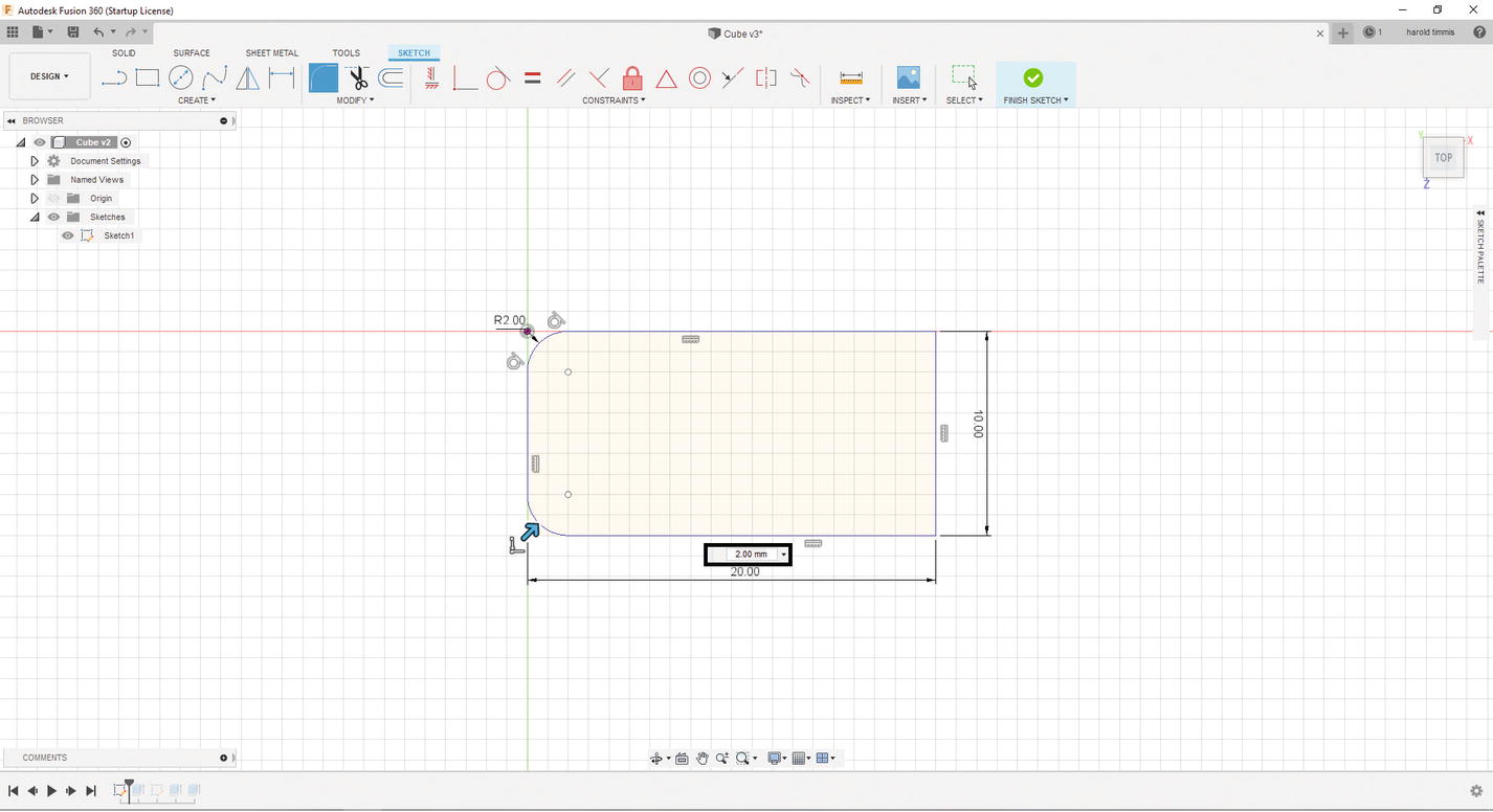
2mm fillets
- 34.
Click the “FINISH SKETCH” button.
- 35.
Now drag the Design History Bar slider to the right after Sketch2 and double-click the Sketch2 icon in the Design History Bar. See Figure 3-78.
Select Sketch2 in the Design History Bar
- 36.
Do the same thing to Sketch2 that we did to Sketch1. See Figure 3-79.
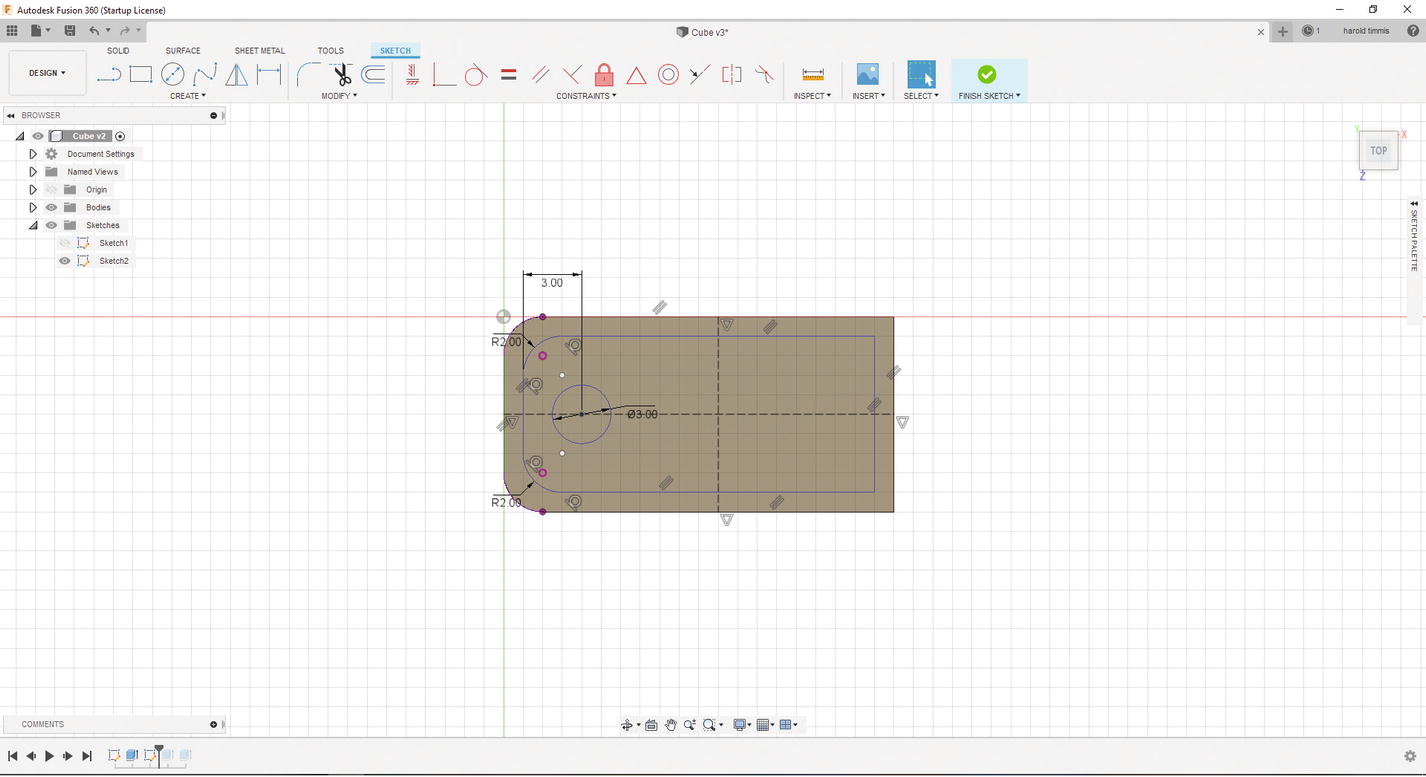
Add 2mm fillets
- 37.
Click the “FINISH SKETCH” button.
- 38.
Move the History slider to the very end and see the result! See Figure 3-80.

Move the Design History Bar slider all the way to the right
- 39.
Make sure you save the project (Ctrl-S).
So, with parametric 3D Modeling, we were able to change our simple cube into a keychain template very quickly and with only a few modifications to the original model.
Now we have a blank keychain template that we can use as an example in the next chapter to 3D print. We will also add an image to this keychain in that chapter.
Summary
Creating a user account for Autodesk
Downloading and installing Fusion 360
Understanding the Fusion 360 user interface
- Fusion 360 sketch tools
Create Sketch
Line
Rectangle
Circle
- Fusion 360 3D tools
New Component
Extrude
Revolve
Sweep
Loft
- Fusion 360 tools
Measure
- Importing files into Fusion 360
STEP, DXF, SVG
Creating a sketch
Extruding a sketch
Parametric 3D Modeling in Fusion 360