Chapter 4. Component Technologies of Head-Mounted Displays
Head-mounted displays for virtual and augmented reality come in a variety of forms, from single eye information displays to fully occluding stereoscopic headsets such as the HTC Vive and Oculus Rift. At the heart of each are two primary component assemblies; image displays and optics. In this chapter we explore the diverse range of these core enabling technologies, identifying the strengths and limitations of each solution.
Display Fundamentals
All head-mounted displays for virtual and augmented reality incorporate the same basic subsystems, although in widely varying sizes and configurations. In their simplest form, these displays consist of at least one image source and optics in a head mount (Melzer, 1997). Depending on the specific display design and intended application, this basic definition will expand to include a variety of different attributes and features, such as second visual display channel, sensors for tracking gaze direction and duration, and more. As will be seen throughout this book, head-mounted displays come in a variety of form factors and sizes and are rarely identical in terms of performance, even when employing the same basic components.
In this chapter, our primary emphasis will be to build foundational concepts concerning the technical performance of these basic subsystems. To this end, we begin with defining basic display categories, followed by reviewing the most common image displays and optical systems.
Ocularity
Head-mounted displays can be categorized by their ocularity, or the specification of their design in serving one or two eyes. To this end, there are three types: monocular, biocular, and binocular. Figure 4.1 illustrates the differences.

Credit: Illustration by S. Aukstakalnis
Figure 4.1 All head-mounted displays fall into one of three optical and display configurations: monocular, biocular, and binocular. These designations define a display’s ocularity.
Monocular
A monocular display provides a single viewing channel via a small display element and optics positioned in front of one eye, with the other eye free to view the normal, real-world surroundings. Typically these devices are of a small form factor and are used as information displays. Examples include various military aviation implementations and devices such as Google Glass or the Vuzix M-100 Smart Glasses (detailed in Chapter 5, “Augmenting Displays”).
Biocular
A biocular display provides a single viewing channel to both eyes. This type of display is most common with head-mounted cinematic viewers as well as those applications in which an immersive capability is needed, but without stereopsis. Generally this type of application is in relation to close proximity tasks. An example of such an implementation is an arc welding training system detailed in Chapter 18, “Education.”
Binocular
The third display category is binocular, where each eye receives its own separate viewing channel with slightly offset viewpoints mimicking the human visual system to create a stereoscopic view.
A summary of these display categories and the primary advantages and disadvantages of each is shown in Table 4.1.

Display Types
Building on the concept of ocularity, there are three general categories for head-mounted displays. The first provides a computer-generated replacement to your true visual surroundings, and the second two provide an enhanced view of the real environment.
Fully Immersive
Fully immersive displays completely occlude the user’s view to the outside world. Fully immersive stereoscopic head-mounted displays (that is, classic virtual reality) combined with sensors to track position and orientation of the user’s head provide the visual sensation of actual presence within a computer-generated environment.
Video See-Through
Video see-through displays are invariably fully immersive as a baseline design, but with the key difference being that the primary imagery displayed within the device comes from either front-facing video cameras or those set in a remote location (telepresence). Depending on the specific application for which the device was designed, those video signals can be combined with computer-generated imagery and output from other sensors. As an example, within the case studies presented in Chapter 17, “Aerospace and Defense,” we look at an application for a video see-through display within which a pilot is able to practice aerial refueling operations with a virtual tanker seen flying outside of their aircraft while using such a display.
Optical See-Through
Optical see-through displays are the key enabling technology underpinning the phrase augmented reality. These systems are designed to overlay, supplement, or combine graphics, symbology, and textual data with the user’s real-world view seen through the optical elements.
Imaging and Display Technologies
The imaging and display technologies employed within head-mounted viewing devices for virtual and augmented systems have made considerable advances over the past two decades. What was once a realm completely dominated at the high end by CRTs has been all but completely replaced by four key imaging and display technologies, each providing a vastly improved, lightweight, and easier to implement solution. In the following sections we will explore the basic functionality of each display type, highlighting the benefits and trade-offs within this application setting.
Liquid Crystal Displays Panels
Liquid Crystal Displays (LCDs) are a relatively mature technology originally used in near-eye displays for virtual and augmented reality as far back as the 1980s by groups such as NASA (Fisher et al., 1986), the University of North Carolina (Chung et al., 1989), companies such as VPL Research (Conn et al., 1989), and others. LCDs are now used in many HDTVs, desktop and laptop monitors, and tablet and cell phone displays.
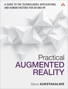
As shown in Figure 4.2, an LCD is an electronically modulated transmissive display device composed of two sheets of polarizing material, the axes of which are aligned perpendicular to each other. Between the polarizing sheets is an array of cells arranged in rows and columns containing liquid crystal molecules. These cells are enclosed on each side by thin glass substrates, upon one of which are printed millions of precisely positioned tiny transistors. Electrical current passed through the liquid crystal in each cell causes the crystals to come into and out of alignment. Varying the current passing through the liquid crystal material allows each cell in the array to serve as a shutter modulating the passage of light.
Credit: Illustration by Lozère via Wikimedia
Figure 4.2 This illustration details the complex structure of an active matrix liquid crystal display. Note that light is provided by an external source.
For color LCDs, an additional substrate is added to the stack containing red, green, and blue filters, or masks, each of which is precisely positioned over an individual cell. Three RGB liquid crystal cells (known as subpixels) form one pixel. When an electrical current is applied, each cell modulates the passage of light based on the intensity of the signal. The combined output from the three subpixels produces the color of the light seen by the observer. If all three subpixels are fully open, the result is a white dot, the color of the backlighting, which is explained next.
Because liquid crystal materials do not emit their own light, the light must be provided by a separate source. Although small LCDs such as those in watches often use reflected ambient light, modern color LCD panels such as those found in some head-mounted displays typically rely upon illumination provided by blue LEDs at the edge of the display panel, which is filtered through a yellow phosphor, and then spread via a diffuser to create a pseudo white light. This light is, in turn, further filtered into different colors by the color mask layer of the liquid crystal elements.
Organic Light Emitting Diode Panels
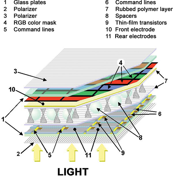
Organic Light-Emitting Diode (OLED) is a solid-state display technology based on organic (carbon and hydrogen bonded) materials that will emit light when electric current is applied. As shown in Figure 4.3, the base layer of an OLED is a thin glass substrate upon which are stacked a series of organic films sandwiched between two electrodes (a metallic cathode and transparent anode). As electrical current travels through the organic layers between the cathode (a conductor) to the anode (an emitter), electrons are given to the emissive organic layer and removed from the conductive layer. The removal of electrons from the conductive layer results in “holes” that need to be filled by other electrons. As these holes migrate to the emissive layer and recombine with electrons (a bound state known as an exciton), energy is released in the form of light, a process referred to as electroluminescence. Although colors can be controlled through the careful crafting of the organic emissive materials used within the OLED, most manufacturers opt for adding red, green, and blue plastic films within the OLED stack.
Credit: Illustration by S. Aukstakalnis
Figure 4.3 This illustration shows the basic architecture of an Organic Light-Emitting Diode (OLED).
There are two main types of OLED displays: Passive Matrix OLED (PMOLED) and Active Matrix OLED (AMOLED). The difference is in the electronics used to drive the display. A PMOLED display uses a complex electronic grid to sequentially control individual pixels in each row (or line) in the display and does not contain storage capacitors. Thus, update rates are slow and the power draw is high to maintain a pixel’s state. In general, PMOLED are used for simple character and iconic displays.
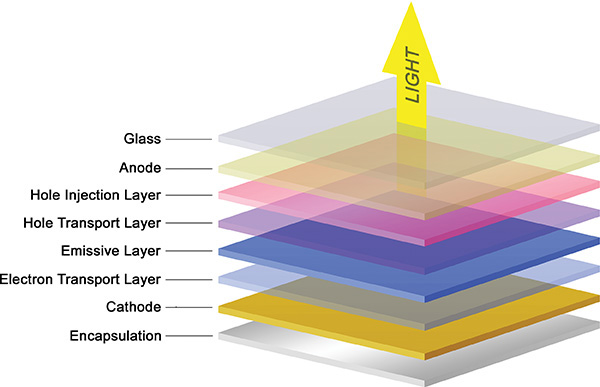
Most applicable to near-eye virtual and augmented reality displays is the AMOLED, a basic design for which is shown in Figure 4.4. Similar to the control of an Active Matrix LCD, an AMOLED is driven by a thin film transistor (TFT) layer that contains a storage capacitor to maintain each subpixel’s state. This provides a significant level of control over individual pixels, including the ability to completely switch them off allowing for deep blacks and high contrast.
Credit: Illustration by S. Aukstakalnis
Figure 4.4 Similar to an active matrix LCD, an Active Matrix OLED (AMOLED) uses a thin film transistor layer that contains a storage capacitor to maintain each subpixel’s state.
In many ways, AMOLEDs are far superior to LCDs. These advantages include the fact that AMOLEDs can be very thin because there is no need for backlighting (they produce their own light), and they have lower power consumption, fast refresh rates, low persistence, excellent color reproduction, and high resolutions. As will be see in Chapter 6, “Fully Immersive Displays,” most commercially available head-mounted displays on the market at the time this book was prepared utilize AMOLED modules as their image sources.
Digital Light Projector Microdisplay
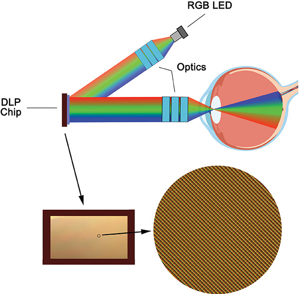
A Texas Instruments digital light projector (DLP) chip, technically referred to as a digital micromirror device (DMD), is a class of micro-electro-mechanical systems (MEMS) known as spatial light modulators. As shown in Figure 4.5, on the surface of this chip is an array of up to two million individually controlled micromirrors measuring ~5.4µ (microns) in size, each of which can be used to represent a single pixel in a projected image (Bhakta et al., 2014). Images are generated by directing an RGB light source to shine on the mirror array while simultaneously sending a video or graphics signal to the DLP chipset, which activates an electrode beneath each DMD mirror. When the appropriate red, green, or blue image channel is to be displayed (a technique known as field sequential color), controllers load a memory cell underlying each mirror cell with a 1 or a 0, causing each mirror to tilt toward or away from a light source with an orientation of ±17°. Tilted toward the light source (+17°), the reflected point of light appears ON. Tilted away from the light source (–17°), the point appears OFF (or dark). As each mirror can be reoriented thousands of times per second, in turn varying the duration that each mirror spends in either the ON or OFF position, different shades of a reflected color can be produced. Used in conjunction with any of a variety of light sources and optics, the DMD device can project efficient patterns of light at high speeds.

Credit: Illustrations courtesy of Texas Instruments
Figure 4.5 This illustration shows the basic architecture of a DLP digital micromirror device. Each highly reflective pivoting aluminum mirror in the DMD chip serves as an independent light switch.
As shown in Figure 4.6, the DLP DMD chip architecture and small size enables considerable flexibility in their integration within near-eye displays for both virtual and augmented reality. In one orientation, the DMD micromirror array is positioned directly in front of the user’s eyes. The array is then illuminated from either the side or the bottom by low power 3-in-1 RGB LEDs, with the light then transferred via optics into the user’s eye to form an image on the retina. A second orientation places the DMD chip off to the side, with the reflected light transferred via waveguide (see the next section) into the user’s eye. In either configuration, the eye itself serves as the last element in the optical chain, with the retina serving as the display surface (Bhakta et al., 2014).
Credit: Illustration by S. Aukstakalnis
Figure 4.6 A Texas Instrument DLP digital micromirror device uses the retina of the human eye as the last element in the optical chain of a head-mounted display.
DMDs represent one of the fastest display technologies in existence. The speed of color refresh and low latency, the high resolution for such a small form factor (a 0.3-inch array diagonal enables a 1280 × 720 image), flexible illumination direction, and low power requirements make DMD an ideal imaging solution for head-mounted displays
Liquid Crystal on Silicon Microdisplay
Liquid Crystal on Silicon (LCoS) imaging technology is a cross between LCD and DLP technologies. As explained earlier in this section, an LCD is composed of an array of cells containing liquid crystal molecules sandwiched between two sheets of polarizing material with one cell (subdivided into red, green, and blue sections) representing one pixel. The state of each pixel is modulated by controlling the phase of the liquid crystal molecules and thus, the passage of light. This makes the LCD a “transmissive” technology. In comparison, DLP displays use an array of individually controlled micromirrors (each representing one pixel) that reflect sequentially projected light from an RGB source. The state of each pixel is modulated by tilting the mirror, making this a “reflective” technology.
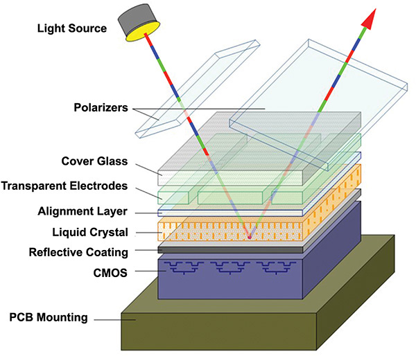
As shown in Figure 4.7, an LCoS device is a combination of both transmissive and reflective technologies. Constructed on a silicon wafer overlaid with a highly reflective coating, LCoS uses nematic or ferroelectric liquid crystal to modulate field sequential colored light reflected off this backplane. Because control circuits are beneath the reflective surface behind each pixel (as opposed to surrounding each pixel as in traditional LCD architectures), there are no obstructions in the light pathway, enabling the generation of substantially clearer images.
Credit: Illustration by Aesopus via Wikimedia under a CC 3.0 license
Figure 4.7 This illustration details the basic architecture of a Liquid Crystal on Silicon (LCoS) chip. Note that an LCoS chip modulates light from an external source to produce an image.
Similar to the DLP DMD solution covered earlier, the LCoS chip architecture and small size enable considerable flexibility in their integration within small form factor near-eye displays for both virtual and augmented reality. A powerful example of one such implementation is the Google Glass monocular head-mounted display.
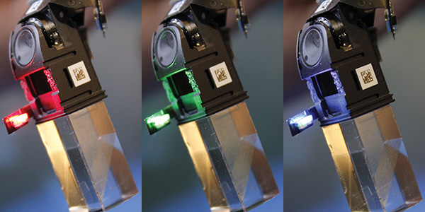
As shown in Figure 4.8, a side-projecting red, green, and blue (RGB) micro-LED array is used to produce field-sequential color illumination. This light is steered through a wedge fly-eye microlens element (shown in Figure 4.9), where it illuminates the reflective inner surface of an LCoS chip. Upon exiting the chip, the resulting modulated light (for each color channel) is reflected off a polarizing beamsplitter and further down the optical path of the display, where it is ultimately steered into the user’s eye.
Credit: Image courtesy of Sid Hazra
Figure 4.8 This image sequence shows the side-projecting red, green, and blue (RGB) LED array used in Google Glass to create field sequential colored light for generation of the appropriate image channels.

Credit: Image courtesy of Andrew Vanden Heuvel, AGL Initiatives
Figure 4.9 This annotated x-ray of a Google Glass display shows a simplified path that a field of sequential light from an RGB LED takes through a wedge fly-eye microlens, into an LCoS chip, off a polarizing beamsplitter, and further down the optical path of the display.
Related Terminology and Concepts
When evaluating display technologies for virtual and augmented reality systems, the lexicon (or jargon) of the field can often be confusing, and perhaps no more so than when dealing with the properties of light. In this section we cover some basic terminology and concepts essential to a solid foundation of understanding concerning the technical performance of displays.
About Light
Light is radiant energy capable of exciting photoreceptors in the human eye. As discussed in Chapter 3, “The Mechanics of Sight,” the human eye is only sensitive to a narrow band within the electromagnetic spectrum falling between wavelengths roughly measuring 380 nanometers and 740 nanometers in length.
Lumen—A lumen (lm) is the unit of measure for quantifying luminous flux (defined next), the total quantity of visible light energy emitted by a source. Most light measurements are expressed in lumens. You will frequently see this unit of measure used in relation to displays based on projection technologies.
Luminous flux—Luminous flux is a quantitative expression of light energy per unit of time radiated from a source over wavelengths to which the human eye is sensitive (380 nm–740 nm). The unit of measure for luminous flux is the Lumen (lm). One watt of radiant power at 555 nm, the wavelength to which a healthy human eye is most sensitive (a yellowish green color), is equivalent to a luminous flux of 680 lumens (Meyer-Arendt, 1968).
Luminous intensity—Luminous intensity is the luminous flux per solid angle emitted or reflected from a point. The unit of measure for expressing luminous intensity is the lumen per steradian, or candela (cd).
Candela—A candela is the unit of measure for quantifying luminous power per unit solid angle emitted by a point light source in a particular direction.
Luminance—Luminance is the measure of luminous intensity per unit area projected in a given direction. Luminance describes the amount of light that passes through, is emitted or reflected from a particular area, and falls within a given solid angle. The unit of measure for expressing luminance is candela per square meter (cd/m2). Readers will also frequently see luminance expressed in “nits” or footlamberts (fL). 1 fL = 3.426 cd/m2.
Illuminance—Illuminance is the luminous flux incident on a surface per unit area. The unit of measure is the lux (lx), or lm/m2 (lumen per square meter). For a given luminous flux, the illuminance decreases as the illuminated area increases.
Brightness—Brightness is purely a subjective attribute or property used to express the luminance of a display. Brightness is perceived, not measured. From a technical standpoint, the words brightness and luminance should not be interchanged (although they frequently are). Brightness is not a measurable quantity.
Display Properties and Characteristics
There are a wide variety of properties and characteristics to consider in relation to head-mounted displays for augmented and virtual reality systems. Each of the following properties and characteristics directly impacts the quality and performance of such displays.
Spatial resolution—The term spatial resolution refers to the number of individual pixel elements of a display and is presented as numerical values for both the vertical and the horizontal directions. For instance, the spatial resolution of the Oculus Rift CV1 is 1200 × 1080 resolution per eye.
Pixel pitch—Pixel pitch refers to the distance from the center of one pixel (RGB triad, LED cluster, and so on) to the center of the next pixel measured in millimeters. This concept is illustrated in Figure 4.10.

Credit: Illustration by S. Aukstakalnis
Figure 4.10 This image illustrates the concept of pixel pitch, which is the distance from the center of one pixel (RGB triad, LED cluster, and so on) to the center of the next pixel and which is expressed in millimeters.
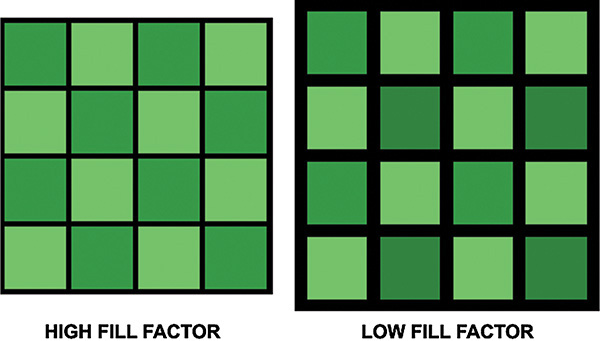
Fill factor—When referring to pixel-based visual displays, regardless of type, the phrase fill factor refers to the amount of black space between individual pixel elements. Because these types of displays are typically composed of a precision array, an excessive black area between pixels can give the visual effect of a fine grid overlay or “screen door” effect when the display surface is viewed close up.
When expressing the phenomenon, the phrase high fill factor refers to minimal black spacing between pixels. A low fill factor would be an expression of excessive black spacing between pixels. This phenomenon is illustrated in Figure 4.11.
Credit: Illustration by S. Aukstakalnis
Figure 4.11 This image illustrates the concept of the phrase fill factor, which refers to the amount of black space between individual pixel elements. A low fill factor results in a strong “screen door” effect in near-eye displays.
Of the four primary imaging technologies covered in this chapter (LCD, AMOLED, DLP, and LCoS), DLP has the least perceptible spacing between pixels (or the highest fill factor) due to the exceedingly small size of the individual mirrors comprising the reflecting surface of the chip.
Persistence—The term persistence refers to the length of time a pixel remains illuminated. Full persistence refers to when pixels remain illuminated for the time span of an entire frame. Low persistence refers to when pixels remain illuminated for only a fraction of the time span of an entire frame. Increasing refresh rate decreases persistence time. Persistence is typically represented in percentages.
Latency—The term latency refers to the elapsed time (measured in milliseconds) between the movement of a head-mounted display and the actual display elements updating to reflect the new scene view. Latency is by no means just a display issue, but the totality of time required for all system components to complete their processing tasks and updated imagery to be displayed.
Response time—The term response time refers to the measure of time a pixel takes to change. Measured in milliseconds, the longer the response time, the more pronounced are the visible image artifacts. Low response times are crucial for head-mounted viewing devices.
Color gamut—The color gamut of a display defines a specific range of colors a device is capable of producing. Although there are a variety of methods used to express a display’s color gamut, the most common are the xy chromaticity diagram of the XYZ color system established by the International Commission on Illumination (CIE), as well as the percentage of the NTSC (RGB) color space.
Contrast—Contrast is a measure of the relative difference between light and dark areas of a display. LCDs tend to be low contrast display, whereas AMOLEDs are high contrast.
Optical Architectures
Optics within a head-mounted display serve three general purposes:
Collimation of light such that an image source appears at a distance greater than its physical distance from the wearer’s eyes;
Magnification of the image source such that an image appears larger than the actual source;
Relay of light patterns from an image source, sometimes located off axis, to the wearer’s eyes (Melzer et al., 2009).
As detailed in the previous section, there are a variety of imaging and display technologies employed within head-mounted viewing devices. Each separate implementation requires its own specific optical design, whether it is to enable users to focus on a flat panel array positioned within inches of their eyes or to relay imagery generated by a microdisplay in an off-axis position such as the side of a display device and into their field of view. In many ways optics are the greatest challenge, and often the limiting factor, in the design of head-mounted viewing devices. Each optical element added to a system means an increase in size and mass of the overall display.
Another significant challenge comes as a result of the fact that head-mounted displays are human-centered systems. The complexity and sensitivity of our sensory mechanisms demands precision and accommodation; otherwise, problems arise, including discomfort, nausea, and an overall poor end user experience.
Basic Concepts
There is not now, and it is likely there will never be, a single head-mounted display device that meets all end user needs. That which is necessary or acceptable for gaming and entertainment with general consumers will be unlikely to serve the needs of professional users. Then there is the consideration of costs. Precision systems for professional end uses such as flight simulation or augmentation will invariably be priced well outside of the reach of the average consumer. That said, there are a variety of optical designs, as well as features and considerations common to all head-mounted displays, about which readers should be aware and are covered in this section.
Field of View
A key consideration in all head-mounted displays for virtual and augmented reality applications is the FOV, which is defined as the total angular size of the virtual image visible to both eyes and which is expressed in degrees (Barfield and Furness, 1995). As binocular displays involve variable amounts of left- and right-eye FOV overlap, it is sometimes useful to express both the horizontal binocular FOV and the total FOV as separate values.
As shown in Figure 4.12, for a healthy adult, the average horizontal binocular FOV, which is the foundation for stereopsis and is important for depth perception, is 120°, with a total FOV measuring approximately 200°. Our vertical FOV is approximately 130°.

Credit: Illustration by S. Aukstakalnis
Figure 4.12 This image illustrates the extremes of the average human horizontal and vertical fields of view.
Binocular Overlap
The binocular field, also known as the area of binocular overlap, is that part of the total visual field within which the monocular FOV for our two eyes overlap. This feature of human vision is extremely important for perception of depth because the relative angles in which objects in a scene are visible gives an estimate of how far this object is located (Boger, 2013).
Interpupillary Distance
Interpupillary distance (IPD) is the distance between the centers of the pupils of the two eyes. This measurement is extremely important for all binocular viewing systems ranging from standard eyewear to stereoscopic head-mounted displays.
As discussed in greater detail in Chapter 21, “Human Factors Considerations,” proper IPD settings are extremely important because poor eye-lens alignment can result in image distortion, the effect of which can be eye strain and headaches and may contribute to the onset of nausea (Ames et al., 2005). Incorrect settings can also impact ocular convergence and incorrect perception of the displayed imagery.
Eye Relief
In a head-mounted display, eye relief is the distance from the cornea of the eye to the surface of the first optical element. Eye relief defines the distance at which the user can obtain the full viewing angle of the display device. This measurement is an extremely important consideration, particularly for those individuals who wear corrective lenses, and in particular, glasses, because eye relief for spectacles alone is approximately 12 mm. As an example, although the HTC Vive (detailed in Chapter 6) allows the user to adjust the eye relief setting to accommodate the use of glasses, the Oculus Rift CV1 (also detailed in Chapter 6) does not. As would be expected, adjusting the eye relief directly impacts the user’s actual perceived FOV within the display.
Exit Pupil
The term exit pupil refers to the diameter of light transmitted to your eye by an optical system.
Eye Box
The phrase eye box refers to the volume within which users can place their pupils and experience the full performance of the device. As shown in Figure 4.13, this volume is dictated by the eye relief and exit pupil.
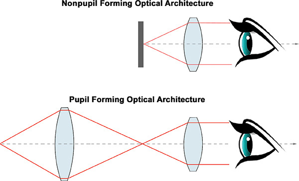
Credit: Illustration by S. Aukstakalnis
Figure 4.13 This image illustrates the most basic configurations for pupil and nonpupil forming optical architectures.
Pupil Forming and Nonpupil Forming Optics
There are two primary optical system designs, or architectures, used in virtual and augmented reality displays: pupil forming and nonpupil forming (Barfield, 2015). Commercially available fully immersive displays such as HTC Vive, Oculus Rift, and Sony PSVR use nonpupil forming architectures. As shown in Figure 4.13, these three systems use a single magnifier to directly collimate light from the display panel.
Although single lens, nonpupil forming optical designs result in lighter, more compact displays, with a large eye box, the trade-off is that they impose significant distortion in the process of bending the light field. The effect is known as pincushion distortion and is illustrated in Figure 4.14. To counteract this effect, images displayed within these viewing devices must be rendered with an equal and opposite barrel distortion to cancel out the effect.
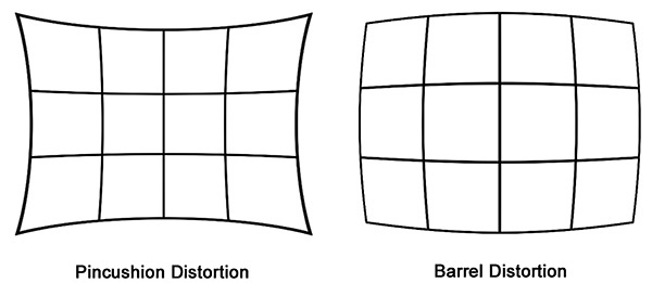
Credit: Illustration by S. Aukstakalnis
Figure 4.14 This image illustrates pincushion distortion, where optics introduce extreme distortion at the edges of the display. This is typically compensated for by rendering images with an opposite barrel distortion. Failure to accurately correct for this phenomenon results in poor depth perception and contributes to incorrect distance judgements.
On the other hand, pupil-forming optical system architectures such as those frequently used in combination with DLP DMD and LCoS microdisplays offer significantly greater flexibility in the overall design of head-mounted viewing devices due to the ability to fold, bend, or otherwise manipulate optical tracks to accommodate different design objectives. Figure 14.15 shows a number of optical elements, beam splitter, and combiner configurations used within these architectures.

Credit: Top optical element illustrations by ElfQrin via Wikimedia under a CC 3.0 license. Combiner illustrations are derivitive works from public domain sources.
Figure 4.15 This image shows a variety of individual optical elements as well as some of the various combiner technologies and strategies used in the design of optical architectures for head-mounted displays.
Waveguides
A waveguide is a physical structure that enables the propagation of light waves through an optical system by internal reflection. As shown in Figures 14.16 through 14.19, the waveguide constrains the movement of light between two surfaces starting from the point at which the light enters the waveguide through to where it exits.
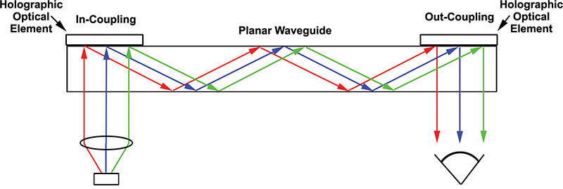
Credit: Illustration by S. Aukstakalnis
Figure 4.16 This image illustrates the basic functional concept behind a holographic waveguide.

Figure 4.17 This adapted patent image shows an example of a basic detractive waveguide design used within a number of commercial and defense optical systems.
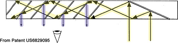
Figure 4.18 This adapted patent image illustrates the basic polarized waveguide technology used within the Lumus DK-50 AR glasses. Arrows highlighted in yellow depict light entering the waveguide and progressing through the various polarized surfaces before exiting (in blue).
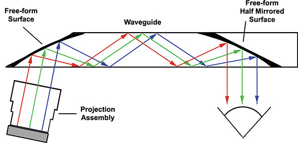
Figure 4.19 This image shows the basic design principle and optical pathway of the Epson Moverio display line.
Although the basic concept of internal reflection is fairly straightforward, from this point the display technology grows in complexity, principally in the means through which light from an image source is introduced into (the in-coupling) and out of (the out-coupling) the waveguide. In general, there are four primary types of waveguides currently employed within existing commercially available augmenting displays:
Holographic Waveguide—Holographic waveguides use holographic optical elements as the in- and out-coupling mechanisms. This technique is currently used within the Sony Smart Eyeglass displays and is illustrated in Figure 4.16.
Diffractive Waveguide—A detractive waveguide contains surface relief gratings with features sometimes measuring in the nanometer range. Detractive waveguides, a basic illustration for which is shown in Figure 4.17, are currently used within Microsoft HoloLens, various Vuzix displays, and a variety of defense and avionics optical systems.
Polarized Waveguide—A polarization waveguide such as shown in Figure 4.18 is a multipart assembly embedding a parallel array of partially reflecting polarized surfaces and multilayer coatings to direct light toward the eye of the viewer. This method was developed by and used within the Lumus DK-50 AR glasses.
Reflective Waveguide—A reflective waveguide such as illustrated in Figure 4.19 uses a single planar light guide with at least one semireflective mirror. This technique is used by Epson in its Moverio product line as well as Google Glass.
Conclusion
Each of the image-generation technologies covered in this chapter has been applied to virtual and augmented reality as an afterthought. None were developed with this particular application setting in mind. The result is that hardware developers are forced into compromises and trade-offs, designing from the outside in, as opposed to the inside out. Complex spatial phenomena are simulated on 2D surfaces, squeezed through sometimes laughable optical systems and presented to our eyes in an attempt to fool the users into believing they’re someplace else.
But these are necessary steps. It is because of these limitations, compromises, and trade-offs that researchers have spent decades digging into the problems, learning how our visual system functions, and deciphering the best ways to format and present structured light patterns to our eyes. Given the host of new display technologies under development, from depth indexed projections using oscillating optical fibers to holographic imaging technologies, it is abundantly clear that the flat panel-based head-mounted displays capturing the attention of the public today will be considered relics in just a few short years.