
CHAPTER TWO
CRUDE DISTILLATION
PROFESSOR POT & KUMAR
I am Professor R.D. Pot! Head of the Chemical Engineering Department at M.I.T. (Mumbai Institute of Technology). I am also a famous consultant for Axxoco Oil.

Good afternoon; I’m Kumar!
Everything I know, I have learned at university from Professor Pot! I’m a Process Engineer at the Crude Unit at the Axxoco Refinery in Bridge City, Texas.

HOW TO ADJUST PUMPAROUND FLOWS
Listen Kumar, my dear friend! Always keep the heavy straight run pumparound (P/A) at its maximum flow so as to maximize crude preheat!

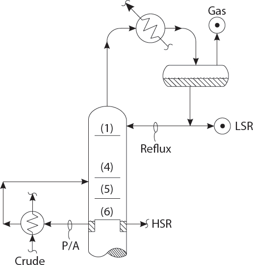
Is that always true, Professor Pot? How will that affect fractionation between LSR & HSR?

Well, I hadn’t thought about that. It seems like taking more heat out in the P/A, will reduce the top reflux rate and make fractionation worse between the HSR & LSR!
But Professor, if the top trays are dirty, and are running too close to their flood point, then reducing the top P/A duty will make them flood and really hurt the split between HSR and LSR, due to flooding and excessive entrainment!
Kumar! You are talking in riddles! Make up your mind! Are you for or against more top P/A heat extraction?
Professor, if we reduce the P/A duty, that may overload the top vapor condenser and make too much gas!
Yes! Yes, Kumar! That’s why I told you to maximize the top P/A in the first place! To reduce overhead condenser load and to save energy, by maximizing the crude preheat, thus reducing the crude heater firing rate!
All true, Sir! But then the LSR 95% point will get too high due to the lower reflux ratio?
Apparently, the subject of optimizing the P/A circulation rate is very, very complex. And we are only discussing one of the three pumparounds on the crude column!
Yes, Sir! May I suggest we ask Norm’s opinion on this subject? He worked on #12 Pipestill in Whiting, Indiana, for American Oil in 1965. After 50 years, he must understand how to adjust the pumparounds on crude distillation fractionators!
HOW TOP REFLUX RATE AFFECTS FLOODING ON TOP TRAYS
Kumar, reducing the tower top tray temperature with more reflux will reduce the volume of vapor flowing to the top tray of the crude distillation tower and stop the tray from flooding!

Are you sure, Professor Pot? It seems like the tower floods if we just raise the top reflux and leave all our pumparounds the same?
Listen to me! I’m a tenured professor here at M.I.T.! Raising top reflux cools off the vapors and shrinks them. Use your common sense!
Please pardon me, Professor! What I see in the plant is that raising the top reflux causes the pressure drop, DP, across the top four trays to increase! Then, if we don’t do something, like increasing the diesel pumparound, we will begin filling up the reflux drum!
Hmmm! Those are symptoms of jet flood! Perhaps the trays …?
Yes, Professor! Yes! The big problem is that raising the reflux rate reduces the molecular weight and thus increases the mole per hour of vapor flow!
Well, that’s true! More moles, more vapor volume per pound of vapor! But certainly the pounds of vapor flow decreases, as the vapors are cooled by the top reflux?
Actually, sir, the weight flow of vapor increases, as the tower top temperature cools, due to more reflux rate!
More mass flow as we lower the temperature at T1? That makes no sense Kumar! Where did you get such an idea from? Certainly not at M.I.T.!
I’m confused about this myself, Professor Pot! I will ask Norm to explain this to me.
Later that Day
Professor, Norm said that when you lower the top few trays’ temperature, by increasing the reflux rate, the sensible heat content of the up flowing vapors would decrease because the vapors are colder. This sensible heat is absorbed by the liquid on the trays, which is saturated liquid at its bubble point. As this liquid absorbs heat from the vapor, it vaporizes to a greater extent. In effect, we are converting the sensible heat content of the vapors, to latent heat of vaporization of the reflux!
Yes, Kumar! And the reduced molecular weight multiplies the effect of increased vapor mass flow rates! I see that!
DESALTER - ADJUSTING MIX VALVE PRESSURE DROP
Kumar! You were always my favorite student! Very serious! May I tell you something important about your crude unit desalter operation?

Certainly, Professor Pot! I always tried my best at M.I.T.
Here are the desalter rules:
- Use 6% volume wash water
- Avoid increasing amps on desalter grid
- Maintain a mix valve delta P of 10 PSI, plus or minus 20%
Hmmm, Professor …? A question? If we have emulsion problems and are carrying over a high BS & W, (1/2 wt% water) in desalted crude, perhaps added mix valve DP is bad? Maybe it would be best to open the mix valve completely? No sense having good mixing and carrying over emulsion, I think?
No! No! dear student! We must always follow the desalter rules, published by the respected chemical vendors! From where do you get such ideas? No desalter mix valve delta P—for shame! For shame!
I apologize most sincerely! But Professor, Norm suggested that not only should we leave the desalter mix valve 100% open, but that it should be removed from the unit and that it’d be …!
What I’ve observed, Professor, is that increasing the desalter temperature will always increase the desalter amps. And, on heavier crudes (20° API), I rather like to have a desalter temperature about 270°F - 290°F. Less viscosity! Of course, the higher temperature increases the conductivity of the crude. And it increases the solubility of water! But as long as the grid does not arc, and voltage is stable — I’m happy!

Yes! But don’t forget that extra dissolved water due to higher crude temperature, will increase the water partial pressure in the crude tower overhead vapors! You don’t want to fall below the water dew point temperature at the top of the crude tower, Kumar! This would cause corrosion and fouling on the upper tray decks.
CAUSES OF TRAY DECK FOULING
Kumar! Dirty tray decks will cause the valve caps to stick to the tray decks! This causes high vapor delta P. Which in turn, prevents the downcomers from draining! Typically, the flooding backs up the tower, from the tray where flooding is initiated. Or, we say, that flooding progresses up a tower, but not down!

Thank you so much, Professor Pot! What then are the indications of crude tower flooding?
Ah, Kumar! What a blessing to have an excellent student! The indications of crude tower flooding; I will list for you:
- Increasing the top reflux rate, increases tower top temperature, rather than decreasing it.
- The heavy naphtha boiling point does not go down, as top reflux rate is increased.
- The crude tower overall delta P increases exponentially, as the crude rate is increased.
- The diesel product will …?
Pardon me, Professor Pot! I may have a very tiny disagreement! I’ve inspected the fouling pattern in several crude towers! They’re all quite similar.
Here’s what I’ve seen:
- The top one or two trays are pretty dirty.
- The next few trays down are so salted up that the photons from a flashlight cannot pass through the bubbling area.
- Once I crawl below the upper half dozen trays, the tray decks are not all that dirty. In the diesel section, the trays are perfectly clean.
- I guess, Professor, maybe that explains why, from what I see, that when a crude tower floods, the overall tower delta P, does not go up all that much.
What? Certainly fouling rates must be higher in areas of the tower exposed to the higher temperatures? Really, Kumar, rates of coke deposition will double for each increase of 25°K! Elementary!
But Professor Pot! Fouling in crude towers is caused by salting-out and refluxing corrosion products down the tower from the overhead condensers! Actually, the big problem we have in Louisiana refineries is MEA. It’s being added to crude as an H2S scavenger in fracked crudes transported by rail cars from North Dakota! It’s the amine salts that are the big problem. Certainly not coke!
HA! Don’t be silly, Kumar! Nobody transports crude by rail! It’s all pipelined! This is America in the 21st century!
MINIMIZING FLASH ZONE PRESSURE
To maximize diesel recovery from crude, Kumar, one must always maximize two variables:
- Heater outlet temperature
- Bottoms stripping steam
Kindly take note of these rules!

Thank you, Sir! I will instruct the unit operators to adhere to these rules! But suppose they ask me if raising the bottoms stripping steam rate, or the heater outlet temperature, causes the flash zone pressure to increase? How should I respond, Professor Pot?
Tell the operators to follow instructions, and not to debate my rules!
I certainly shall, Sir! But I’ve seen that if one is limited by overhead condenser capacity, that increasing bottoms stripping steam will pressure up the flash zone and suppress diesel yields. Also, as Clare has explained to me, “No sense putting more heat into the tower, if you can’t take it out!”
Clare? I’ve told you that Indian engineers should not interact with females! It just confuses application of standard engineering principles! Why would more heat and more steam increase the flash zone pressure anyway? Those variables are not related on my crude tower Aspen computer simulation. Go back and check your modeling variables, Kumar!
Professor! What you say is 100% correct! The crude tower pressure should stay constant! The difficulty is that we are limited in the summer by overhead condenser heat removal capacity in our aerial fans!
Nonsense, Kumar! Those overhead air coolers have plenty of spare capacity! You must check their data sheet! Use your head, my dear boy!
Yes, Sir! I shall! But the problems are:
- The air fan belts are slipping!
- The fins are dirty!
- The blade pitch is 10°, not the optimum of 22°!
- The diesel P/A pump is running below its curve value!
- The upper trays in the tower are salted-up!
- The off-gas compressor rotor is also fouled!
- Ambient air is above the design air cooler temperature!
- Steam leaks are blowing into the air cooler fans!
- The ammonia chloride salts are …!
Stop Kumar! I’ve heard enough! If you would pay more attention to computer modeling of the crude unit, and less to these mundane problems, you would make a better manager! Hmm? Perhaps an email to Dr. Petry would be in order? We should let the Director of Maintenance know about your concerns!
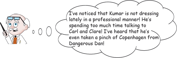
HOW TO ADJUST BOTTOMS STRIPPING STEAM RATE
Mr. Kumar! The stripping steam in the bottom of a crude distillation unit should always be maximized, up until the point of flooding of the stripper trays or of the upper trays in the crude tower! This is done to maximize diesel recovery from vacuum tower feed! It’s a rule!
Yes! Thank you for that excellent advice, Professor Pot! But Sir, I have some other concerns in mind. May I mention them?
It’s best to follow our rules! And how is your lovely new wife Sonia? Is she a good cook? You’re getting a little heavy! Ha! Too much rich curry!
Sonia, unfortunately, does not engage in cooking. She is the lead software engineer for Exxon! But Professor, I’ve noticed that when I raise the stripping steam rate past 17,000 lbs/hr on my crude unit, some negative factors emerge! Sir, permit me to list my observations:
- Crude tower pressure increases, due to lack of overhead condenser capacity.
- The vacuum tower pressure increases, as does the off-gas rate from the seal drum.
- The LVGO rate goes up.
- Crude tower diesel production goes down.
Well, my boy! You should make a more vigorous effort to clean your overhead condenser air cooler fin tubes. Make sure the belts are not slipping! Water wash the bottom few rows of tubes, being cautious not to damage the Aluminum fins with too much water pressure!
Check the blade angle – 20° to 25° is best! Try reversing the polarity of the AC motors. That will blow dirt off the lower rows of tubes. Are you remembering to slug water wash the tube side, as we talked about in class?
Yes, Professor Pot! I’ve been doing all these things you taught us at MIT! The problem is it gets so hot in the summer that often more stripping steam hurts rather than helps. Mainly then, I try to optimize the crude tower bottoms stripping steam rate, to maximize the vacuum in our asphalt vacuum tower!
Yes, Kumar! Rules must be adjusted to fit individual circumstances!

Kumar! Have you considered a water mist to cool the air flow by humidification during hotter summer days? This would reduce the air cooler effluent temperature by about 4°F.
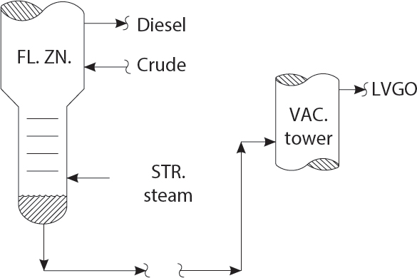
OVERHEAD CONDENSER CORROSION
I see from the maintenance monthly report, Kumar, that you are experiencing an overhead condenser tube failure every few months! You must change to Titanium (Ti) tubes at once! A Titanium tube bundle will not corrode at all!
Oh! Professor Pot! I’m afraid that just changing the tube bundle will not stop corrosion in the overhead vapor line, or the condenser shell! Norm recalled that in 1968, at the Amoco Refinery at Texas City, they changed No. 3B pipe still overhead condensers to Ti. Then, the C.S. vapor line failed and almost destroyed the refinery!
Well! Norm should know! He was likely partly responsible for many of the disasters at that terrible refinery. Well, if not Ti – what does Norman suggest?
Of course, the tower top temperature at T2 must be kept 10°F – 20°F above the water dew-pt. temperature, taking into account the partial pressure of ammonium chloride, which may escalate the water dew-pt. temperature by 10°F - 30°F. And then enough water should be added to exceed the rate needed to reach the water forced condensation dew-pt. temperature at T1.
Quite true! Do you recall, Kumar, how to calculate the amount of wash water required to reached the forced condensation water dew-pt. temperature? You can use your Aspen Simulation!
Well, Sir! I have an alternate method! I observe the temperature at T1! Then, I’ll increase the wash water rate until the temperature at T1 stops dropping. That, Professor Pot, is the forced condensation dew-point temperature!
Very clever! Of course more water is always helpful! One should design for 2x the wash water rate needed to reach the water dew-pt. temperature at the condenser inlet! By the way, which chemical vendor does Mr. Lieberman recommend, Kumar?
None! He suggests that NH3 can be used as a neutralizer for the HCl formed from the hydrolysis of the MgCl2 to Mg(OH)2 + HCl! Ammonia is a tiny fraction of the price of neutralizing amines! The NH3 is mixed with the water wash, before it is sprayed into the vapor line to each condenser.
NH3! Certainly not! All the chemical vendors recommend a proprietary neutralizing amine!

ON-LINE SPALLING OF CRUDE PRE-HEAT EXCHANGERS
I see, Kumar, that your kerosene pumparound vs. cold preheat exchanger has fouled! I’ve calculated a “U” value of 12 BTU/HR/FT2/°F! Its design “U” is 62. What did you measure the DP on the tube (crude) side at? The tube side calculated DP at the current crude rate is 6 psi!

Professor, the measured DP on the tube crude side was 42 psi! Seven times greater than the calculated DP! This proves, Sir, that you were correct! The exchanger was terribly fouled on its tube side!
I notice, my boy, that you are using the past tense regarding the fouling. Do I also need to instruct you on grammar, in addition to basic engineering theory?
Very sorry, Sir! The exchanger was fouled yesterday, but I cleaned it this morning! Its coefficient is now 38 BTU/HR/FT2/°F, and its pressure drop has decreased from 42 to 16 psi! I should have so informed you! I apologize for my tardy reporting!
What! You cleaned it yourself? Without the maintenance department? John Brundrett, the maintenance supervisor, will be extremely angry! What will I tell him?
Pardon, Professor Pot! Permit me to explain. I employed the following steps to clean the tube side:
- Block-in the tube inlet, but leave the crude outlet valve open.
- Leave the hot, shell side flow without change.
- Open the 1″ LCO (or any aromatic type hydrocarbon) flush line. This step is not really all that important.
- Wait 15 minutes.
- Return to normal operations!
Norm calls this, “On-line Spalling.” It’s a method he discovered by accident during a power failure at the Amoco Refinery in Whiting, in 1967. It works great!
And what about the fouling particulates that are “Spalled-off” in this irresponsible, nonstandard procedure? Where do they migrate to, if I may ask, Kumar?
Sir! I presume the spalled-off solids, are withdrawn from the desalter vessel during the mud-wash period. I suppose that is why Norm only uses this procedure on crude preheat exchangers, upstream of the desalter?
Hmmm …? I believe, Kumar, that the coefficient of thermal expansion, of the fouling layer, inside the tubes, would be less than the tube metal itself! Thus, the deposits would shear-off, due to the rapid change in temperature, and the sudden restoration of crude oil flow!
Kumar! May I suggest you have some safety people stand by during this on-line spalling procedure, in case the thermal stresses cause flange leaks to the crude side connections!
EFFECT OF REFLUX ON OVERHEAD ACCUMULATOR TEMPERATURE
Kumar! You have made a small error! The crude unit performance test report shows increasing the top reflux rate, reduced the tower top temperature at T1, but increased the drum temperature at T2? A careless mistake! Of course, the drum temperature must go down, if you have cooled off the top of the tower with more reflux! It’s all right, dear boy, the rest of your report was excellent! I have also made errors in my long career! Don’t be too upset!

Thank you, kind sir! But it was not an error. I observed this effect in the field, and my observations are in agreement with my heat exchange calculations!
But, but, but? My dear young colleague! Certainly a reduction in the condenser inlet temperature would result in some reduction in the condenser outlet temperature? That is just plain common sense! You must agree?
Perhaps Professor Pot, I am mistaken! But here is my analysis, which God willing, is correct:
- Assume the crude tower flash zone and pumparound duties are constant.
- Therefore the overhead condenser duty (Q) is mostly constant.
- Q = U • A (Delta T)
- Assume (U • A) is constant.
- Therefore, Delta T is mostly constant.
- Also, the condenser’s cooling water inlet and outlet temperatures must be constant, since Q is constant.
Quite clever, Kumar! If delta T is constant, then a reduction in the tower top temperature would lead to a reduction in delta T at the hot end of the condenser! Which must result in an increase in the condenser outlet temperature, to increase the cold-end condenser delta T! No wonder you were my prize student at M.I.T. But in practice, have you really observed this hotter reflux drum temperature, due to a greater reflux rate?
Yes, sir! It happens frequently on our crude unit! Also, the hotter drum increases the off-gas rate from the reflux drum, which, unfortunately, is flared! We can stop the flaring at #12 Pipe Still, by increasing the tower top temperature with less reflux. But then, our naphtha end-pt. gets a bit high!
Kumar! Combining theory and observation to draw conclusions is the sign of a brilliant engineer! Well done, my boy!
It rather seems, Kumar, as if your analysis should also apply as well to the FCU, Visbreaker, and to the Delayed Coker Fractionators!
REMOVING TRAYS FROM PRE-FLASH TOWERS
Well, Kumar! I see that you wish to remove half of the 12 rectification trays in the crude pre-flash tower! My fine fellow, this is not a good idea! It will negatively affect fractionation efficiency!

But, Sir! I need to have an additional 12 ft. above the feed inlet nozzle, to allow vertical height, for foam to settle and prevent black naphtha, which ruins the desulfurizer catalyst!
Yes, yes! A worthy objective! Especially crudes that have been delivered by pipeline will have flow-improver chemicals added to them, which may cause such crudes to foam at 350°F-400°F. But Kumar, won’t the pre-flash tower naphtha end-point be substantially increased, by removing half the trays?
No, Professor Pot! The extra 6 trays are superfluous! The molal ratio of V/L on these trays is only about 0.3. When the ratio of V/L becomes small, having 12 trays, vs. 6 trays, does not affect the rectification section fractionation efficiency, to any great extent! Sir, it’s rather the same concept you taught us at M.I.T., when we studied the McCabe Thiele Diagram. Specifically, when we studied the concepts of “pinch-point” and “minimum reflux rates.”
Yes, Kumar! You are correct! Your analysis is also supported by my Aspen Process Model, which shows removing half the trays has only increased the pre-flash naphtha ASTM D-86 95% point by 5°F. Why risk foaming and flooding, for only 5°F worth of fractionation? Good work!
Thank you for your kind words, Professor Pot! My wife has sent some curry for my lunch. May I offer you a portion? It is extremely spicy! Just like we have at home in Mumbai!
Thank you, I’ll have just a small cup!

TOTAL TRAP-OUT CHIMNEY TRAY
We must install a new kerosene draw-off in No. 2 Crude Unit during the May turnaround! We can install a draw-off sump below tray #14 for this purpose. Kumar, check that the delta P of the vapor flowing through the valve caps is not less than 2″ of liquid, to make sure the tray will not leak and thus allow the by-pass of kerosene around the new draw-off pan sump!

Sir! If this was a five foot diameter crude tower, I would agree with you! But this is a twenty foot diameter tower. The larger the tower diameter, the greater the probability that the tray decks will be out-of-level! If the tray has a sag of several inches, then the tray deck will leak!
Ah, yes! I see your point! We may lose a large quantity of kerosene through the low point of the tray! But that’s life, my young friend. You will just have to inspect the trays carefully for levelness during the turnaround!
I am honored, Professor, that you consider me a friend! But, sir, there is also the option of installing a Total Trap-Out Chimney Tray, with provision for internal overflow. Such a tray should have been:
- Sloped, 1″/foot, in direction of flow.
- Sealed to the tray ring, with a 3″ × 3″ expansion ring.
- Constructed out of 8 gauge, 316 (L) stainless steel, or 317, for additional naphthenic acid protection.
- Water tested for leaks prior to start-up.
- No drain holes.
But Kumar! We will lose a fractionation tray! And also degrade fractionation between kerosene and diesel!
Professor, as usual, you are correct! However, the loss of a single fractionation stage will only increase the D-86 ASTM distillation 5%-95% overlap, from 25°F to 30°F! A small price to pay, to insure the ability of being able to always maximize kerosene production! May I show you my Aspen simulation results?
Agreed! It will be a chimney tray, for the new kerosene product draw-off! I especially like the ideas of sloping the tray in the direction of flow and also the 3″ × 3″ expansion ring.

SIDE DRAW-OFF LIMITATIONS
Let us increase diesel production! Kumar, the diesel side draw-off control valve is only open 15%! Open it to 50%! This ought to double the flow of diesel. We are overflowing the top of the chimney! That is very bad! The diesel is running down the tower into the gas oil draw! That’s $20/barrel product downgrading, my boy!

Thank you, Professor Pot, for your wise advice! Most unfortunately, Sir, opening the diesel draw valve will not increase product flow whatsoever! My apologies!
Well, it’s not your fault, dear student! But certainly, as the sump is full, as indicated by the level transmitter, more flow must be possible! Can you not see the truth of my logic?
So sorry, Sir! While your logic is, as usual, brilliant, there is a problem! You see, Professor, that the liquid at point B is in equilibrium with the vapor! The liquid at point B is at its boiling, or bubble point! As this liquid flows through the draw-off nozzle, it accelerates to velocity “V.” The energy to accelerate this liquid comes from the head of liquid, H, in accordance with this formula:
H = 0.178 • V2
If the pressure at point A, falls below the pressure at point B, the liquid at point A will boil. The giant vapor volume expansion in the nozzle causes vapor lock, and prevents any increase of flow!
Brilliant analysis! But about the 0.178 coefficient! How was this derived? Let us assume H is expressed in inches, and V is expressed in ft/sec!
Well Professor Pot, it’s a theoretical coefficient, based on converting potential energy into kinetic energy! It makes no allowance for friction in the draw-off nozzle! Norm says he uses a 0.30 coefficient in sizing new nozzles, to allow for friction! But this assumes that there is no vortex breaker in the nozzle!
But of course, Kumar! If the nozzle exit velocity exceeds 4 ft/sec, a vortex breaker is most certainly required! However, for velocities of less than 2 ft/sec, vortex breakers are best omitted!

Kumar! Will you join me in a cup of green tea? I believe that the problem you have described is referred to as “Nozzle Exit Loss Cavitation Limit”!
PACKED TOWERS
Kumar! We must always strive to use the best available technology in our designs! For that reason, we should prepare a revamp design using beds of structured packing and high-capacity perforated rings for our crude distillation column!
Thank you, Professor, for your wise advice! But sir, for what purpose do you suggest we remove the existing grid trays, and replace them with beds of packing?
Dear student! As usual, you have asked a perceptive question! The rings or dumped type packing will be used in the fractionation zones. Dumped type packing may have an HEPT (height equivalent of a theoretical plate) of as little as 20 inches! Likely, this would give us double the number of fractionation stages for the same height of trays! The structured packing would be for the pumparound section, where it would increase capacity, compared to multi-pass trays, by 30%!
Yes, Professor Pot! Packing of various types are in widespread use in modern process plants throughout both India and America! But I’ve asked Norm about his experiences! He has graciously bestowed on me his ten “Rules of Thumb for Packed Towers.” May I be permitted to email you Norm’s rules?
RULES OF THUMB FOR PACKED TOWERS
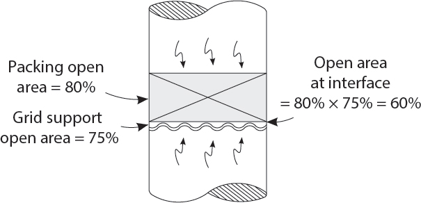
- Packing capacity is proportional to the open area of the packing, times the open area of the grid support. NOT, just the open area of the packing alone.
- Fouling occurs at interface between grid support and packing. And, at the top of the packing.
- Dumped packing cannot be inspected while packing is being loaded. Don’t use rings or saddles.
- Each layer of structured packing must be inspected after it is laid down. Watch that it is not crushed while the upper layer is installed.
- Always put a layer or two of grid between the packing support and the packing.
- Packing does NOT redistribute liquid. Small liquid rates (a few gpm/ft2) are very tricky to distribute.
- Always use a hold-down grid, above packing, but keep it a few inches below liquid distributor.
- Do not use orifice plate, chimney tray type liquid distributors. They lead to bad liquid distribution if slightly out of level.
- Provide for internal overflow for total trap-out chimney tray - vapor distributors. Do not overflow through chimney slots.
- Don’t use packed towers. The final installation cannot be inspected. The best choice for new towers is ancient BUBBLE CAPS, which outperform in efficiency (but not capacity) all new tray developments.
Ha-ha! Bubble cap trays! Norm should always be treated with respect due to his advanced age! We, as Indians, must always respect our elders. But the use of bubble cap trays in crude distillation was already outmoded technology when Norm began his career in 1965 for the American Oil Company, in Whiting, Indiana!

Author’s Note – I last ran into bubble cap trays at a refinery in New Jersey, built in 1954. They were welded-in trays, could not be replaced, and appear to be working reasonably well after over 60 years of service.
CONTROLLING AGO DRAW-OFF RATE
Kumar – dear friend, colleague, and former student. Kindly obtain a sample of atmospheric gas oil from the lower side-cut of our crude distillation tower! Submit it to the laboratory for Ni and Va! Also for conradson carbon. The FCU is complaining, once again, as to the quality of their feed! They suspect it’s our AGO that is the culprit that is degrading their catalyst activity!

No need for a lab sample, Professor! Our AGO sample is transparent! This indicates that it is free of asphaltenes. It is these highly condensed aromatic rings that make up the asphaltenes that contain the Ni and Va, that contaminate FCU catalyst! They’re part of the molecular structure of the asphaltenes!
But Kumar, what you say is not correct! I myself, with my own eyes, have just seen in the Shift Foreman’s office a bottle of recently drawn AGO! The sample was quite greenish, and totally opaque! Certainly not transparent as you have described!
So sorry to be argumentative, sir! You cannot judge the quality of gas oils – either AGO, LVGO, or HVGO, by their appearance, when they are cold, in a large container, such as a pint sample bottle. The sample must be obtained in a small, 1 oz. bottle, and heated to the temperature of hot jasmine tea, so as to melt the wax crystals! As long as such a sample is transparent, it is free of asphaltenes! Hence, also free of metals! Even 4 con carbon HVGO will be excellent FCU feed, if it is transparent, as I have described! Norm produced such FCU feed in Aruba, for a FCU feed hydro treater, and it was fine!
Here in America, we must say we heat the gas oil sample in a cup of hot coffee – not tea – as we would do in India! We must always accommodate ourselves to local customs! Ha ha ha!
Kumar! Perhaps we had best base our gas oil quality on percent hexane insolubles, as a better measure of asphaltene content than concarbon!
FILMING AMINE PLUGS OVERHEAD VAPOR LINE
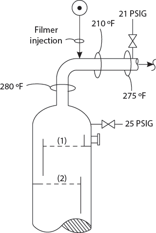
Kumar! Your recent crude tower overhead pressure drop survey shows a 4 psi. That is, DP = 25 psig minus 21 psig! Have you calculated the vapor outlet nozzle exit loss using the correct formula?
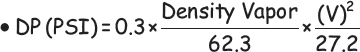
Where V = Nozzle Velocity, in ft. per second
Yes, Professor, I have! The calculated nozzle exit loss is one psi!
No Kumar! Very sorry! The observed and calculated nozzle DP should be the same! I believe, my boy, that you have made an error – either in your calculations, or in your measurements.
Pardon me, Sir, if I may take the liberty to observe, that the 16″ crude tower overhead vapor line is partially plugged! Apparently, the filming amine is restricting the vapor flow and causing an excessive pressure drop!
How can you know that, Kumar? Have you developed X-ray vision? Can you now see through steel pipes – like Lois Lane? She is Superman’s …!
Pardon, Professor! Miss Lane is Superman’s girlfriend. However, their relationship is purely platonic! My observation that the vapor line was partly plugged, downstream of the filming amine injection point, was based on a skin temperature survey! The localized cold section of 210°F – about two or three feet long, could only be attributed to a local fouling layer! This is a common problem on very many crude units that employ filming amine!
Hmm? This is bad! A high vapor line pressure drop will increase the crude tower flash zone pressure, and reduce the diesel recovery from the vacuum tower feed! That extra 3 psi DP may be costing us $30,000 a day! We should ask the Operations Division to cease the use of filming amine as soon as possible. I shall email Mr. Frank Citek at once. Only yesterday Mr. Citek criticized me for the lack of tech service contribution to refinery profitability!
But Sir! The filming amine is quite useful in protecting the overhead vapor line from corrosion, due to the HCl evolved from the hydrolysis of Mg (Cl)2 salts in crude! It is not so much that the filming amine is at fault, but that the crude unit operators are not consistently adding the dispersion naphtha into the flow of the filming amine! Perhaps a note to Mr. Citek, pertaining to the importance of the dispersion naphtha would be useful, as he is the operation’s manager.
Yes! I quite agree! Kindly draft such an email to Frank Citek. But make sure you explain the difference between filming amine and water soluble neutralizing amine! I fear Mr. Citek does not know the difference!
Note from Norm
Frank Citek was Amoco East Plant Operation’s manager in Texas City in the 1970s. I remember him screaming at me one day, “Lieberman! Stop complaining! We make our own luck!” The other lesson he taught me was, “The performance you get from people is not what you hope or expect, but the minimum you are willing to tolerate!”
STRIPPING TRAY PRESSURE DROP PROFILE
Dear Kumar! Your pressure drop survey on the crude unit distillation tower bottom stripping section is in error! My boy, the pressure you have shown above tray #4, is one psi larger than below tray #1! This is quite impossible! Please revisit your field measurements! You may have accidentally reversed your pressures.

Sorry Sir! I was quite careful! The pressure above tray #4 is slightly higher than below tray #1.
Very well! But how can you explain your results? Certainly, vapor cannot flow on its own, from 3 to 4 psig?
Certainly Sir, you are correct! My explanation is that we have lost the downcomer seal from tray #4. Likely the downcomer is too short, or the outlet weir from tray #3 is badly out-of-level!
Yes, Kumar! These sorts of installation problems are quite common. Or the tray #4 tray deck might be damaged? Who knows? Tray installations in this country are often done carelessly. Not like in India!
Yes, Professor! And then, the liquid would stack up above tray #4, because it would have to flow through the sieve tray’s ![]() ″ orifice holes or the grid tray’s fixed valve caps! If the s.g. of the liquid was 0.70, then a back-up of 40 inches of liquid above tray #4 would indeed produce a head pressure of one psi!
″ orifice holes or the grid tray’s fixed valve caps! If the s.g. of the liquid was 0.70, then a back-up of 40 inches of liquid above tray #4 would indeed produce a head pressure of one psi!
Ah yes, dear student! You can confirm your theory by measuring the pressure in the flash zone! It should read a bit less than 3.0 psig! Also, I imagine that the stripping efficiency of bottoms is poor?
You are correct Sir, on both counts! I checked the ASTM D-86 distillation of the crude tower residue. It’s 16% 650°F and lighter! That is diesel, kerosene, and even naphtha is being lost to the vacuum tower feed! And then these valuable distillates flow straight on to the FCU with the LVGO product! Terrible!
Disgraceful! This could never happen in Mumbai! But once Donald Trump becomes President of the United States, such inefficiencies will be eliminated!

PROTECTING CRUDE TOWER STRIPPING TRAYS FROM DAMAGE DUE TO WATER IN STEAM
Kumar! Bad news! The Inspection Department has reported that the crude tower bottom stripping trays have been found dislodged from their tray ring supports once again! Dr. Petry is quite concerned!

Professor! We need to install a restrictive steam sparger!
A what? Is that like a steam distributor – or is it something else? What is its purpose, Kumar?
Well yes, Professor Pot! It’s rather like a steam distributor. However, the total hole open area is quite small! Hole velocities, for a crude tower, are approximately 200 to 400 plus feet per second! The hole pressure drop is a few psi. The distributor pipe is made of “triple X” thick pipe! Then, in case a slug of water enters the sparger, along with the stripping steam, the sparger will pressure-up, as the water flashes, and trips off the supply of steam to the stripper!
So, a new trip valve is required for this concept? That would be quite costly, my boy!
No, Sir! We would simply use the existing steam flow FRC as the trip valve! Professor, you can see the details of the design, which has been used at many refineries, in the Appendix to the 2nd Edition of Process Design for Reliable Operations.
And who, dear student, is the author of this text? It’s not that Lieberman fellow, I hope?
Unfortunately, Sir, this book was authored by Mr. Lieberman! Still, his design has been used with good results in vacuum towers in California, Louisiana, and Aruba! Also, Professor, Norm says we should use for the stripping tray design for improved mechanical integrity:
- Explosion doors in tray decks
- 10 gauge trays (4 mm) thickness
- Shear clips
- Back-to-back tray decks
- Bolted-in tray panels
- Grid tray, rather than valve or sieve tray decks
Fine, Kumar! But I imagine this will double both the cost and installation time of these exotic replacement trays!