CLC (Configurable Logic Cell)
The Configurable Logic Cell (CLC) is a module designed by Microchip that provides basic configurable logic for PIC® microcontrollers. This includes the basic gates and D and JK flip-flops and D and SR latches. This means that with the CLC, you can combine logic internal and external to the chip to produce a particular function. The CLC can even wake the microcontroller up from sleep.
Microchip provides many examples to use the CLC and they will not be repeated in this book; instead, we look at a simple example. In this example, we demonstrate the CLC by configuring it as a four-input AND gate.
The inputs of the CLC are each connected to switches. If any of the switches is pressed, the respective input of the AND gate becomes a logic low and the LED is switched off.
We will begin by selecting the CLC option from the MCC Device Resources (see Figure 12-1).
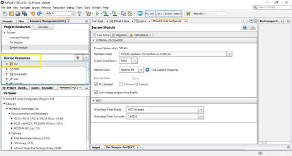
Figure 12-1 MCC screen
Next, double-click the CLC peripherals option from the Project Resources tab. Set the mode to 4-input AND and ensure that the output is not inverted. At each of the four OR gates, you will notice four lines marked with X. Click the first, second, third, and fourth of these and select the inputs as CLCIN1, CLCIN2, CLCIN3, and CLCIN4, respectively, as shown in Figure 12-2.
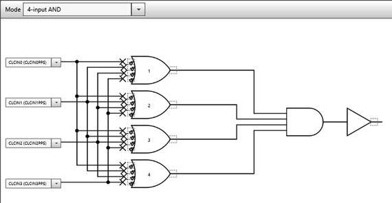
Figure 12-2 Selecting inputs
Figure 12-3 shows the finished setup.
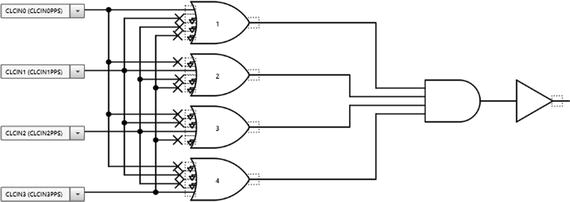
Figure 12-3 Finished setup
Choose Pin Manager: Package and Pin Manager: Grid and select your input and output pins, as shown in Figure 12-4.
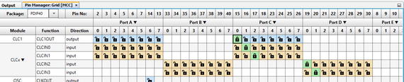
Figure 12-4 Selecting pins
Click Generate and program! That’s it! There is no main code to be written by the developer. The MCC makes it very easy for a developer; however, in this book I deliberately avoided the use of the MCC to allow you to get a good understanding of the underlying hardware. In the case of the CLC, the MCC has a visual configuration tool that is very simple to use.
NCO (Numerically Controlled Oscillator)
The PIC® microcontroller has always been a cut above the rest in matters relating to onboard peripherals. The Numerically Controlled Oscillator (NCO) is one such peripheral that was introduced to PIC® microcontrollers. The output of the NCO is a square wave that’s dependent on the input clock and the value given for the increment postscaler.
The NCO, like the CLC, operates independently from the core, which means that once it is set up in this example, we won’t have any code to write. All you have to do to see this square wave is connect the probe to the output pin. This process is really straightforward. If you have never used an oscilloscope, it’s best to consult you user manual. There are also plenty of resources on the web showing you how to use your oscilloscope. If you are using a Velleman pocket oscilloscope, connect the ground to the ground rail first and leave the attenuation at 1x. The scope will do the rest.
Let’s write some code to generate a square wave, as shown in Listing 12-1.
Listing 12-1 NCO Source
/** File: Main.c* Author: Armstrong Subero* PIC: 16F1717 w/Int OSC @ 16MHz, 5v* Program: 27_NCO* Compiler: XC8 (v1.38, MPLAX X v3.40)* Program Version: 1.0*** Program Description: This Program Allows PIC16F1717 to use the NCO** Hardware Description: An oscilloscope probe is connected to PIN C0** Created November 4th, 2016, 1:00 PM*//********************************************************************************Includes and defines******************************************************************************/#include "16F1717_Internal.h"/******************************************************************************** Function: void initMain()** Returns: Nothing** Description: Contains initializations for main** Usage: initMain()******************************************************************************/void initMain(){// Run at 16 MHzinternal_16();/////////////////// Set UP NCO////////////////TRISCbits.TRISC0 = 0x00; // Port C as digital output portANSELC = 0;bool state = GIE;GIE = 0;PPSLOCK = 0x55;PPSLOCK = 0xAA;PPSLOCKbits.PPSLOCKED = 0x00; // unlock PPSRC0PPSbits.RC0PPS = 0x03; //RC0->NCO1:NCO1OUT;PPSLOCK = 0x55;PPSLOCK = 0xAA;PPSLOCKbits.PPSLOCKED = 0x01; // lock PPSGIE = state;LATCbits.LATC0 = 0;// Enable NCONCO1CONbits.N1EN = 1;// Operate in Fixed Duty cycle modeNCO1CONbits.N1PFM = 0;// Output signal active highNCO1CONbits.N1POL = 0;// Clock is 16 MHzNCO1CLKbits.N1CKS = 0b01;// NCO incrementNCO1INC =0x3334;}/******************************************************************************** Function: Main** Returns: Nothing** Description: Program entry point******************************************************************************/void main(void) {initMain();while(1){// Connect scope to RC0}return;}
Comparator
A comparator is a device that compares two analog voltages and outputs the difference between them. Essentially, a comparator outputs either a high or a low based on the voltages as its inputs. A comparator can be thought of as a crude 1-bit analog to digital converter since it is converting an analog representation of voltages into a format that can be interpreted by a digital system.
The PIC® microcontroller has a comparator onboard. This comparator operates independently. In the following example, we put the CPU to sleep while the comparator is running. The comparator can also have its output directed internally or externally. In the example in Listing 12-2, we make the comparator output externally available.
Listing 12-2 Comparator Source
/** File: Main.c* Author: Armstrong Subero* PIC: 16F1717 w/Int OSC @ 16MHz, 5v* Program: 12_Comparator* Compiler: XC8 (v1.41, MPLAX X v3.55)* Program Version: 1.0*** Program Description: This Program uses the onboard comparator module of* the PIC microcontroller. When the voltage at Vin+ is* more than the voltage at Vin- the comparator outputs a* logic level high and vice versa.** Hardware Description: An LED is connected via a 10k resistor to PIN RA3 and* the output of a 1k voltage divider is fed into the* - input (PIN RA0) of the comparator with the + input* (PIN RA2) being the output of a 10k pot is fed into* the positive end.** Created March 24th, 2017, 12:48 PM*//********************************************************************************Includes and defines******************************************************************************/#include "16F1717_Internal.h"/******************************************************************************** Function: void initMain()** Returns: Nothing** Description: Contains initializations for main** Usage: initMain()******************************************************************************/void initMain(){// Run at 16 MHzinternal_16();//////////////////////// Setup Comparator1///////////////////////_____________// RA0 = C1IN0-//_____________// Set as inputTRISAbits.TRISA0 = 1;// Set analog mode onANSELAbits.ANSA0 = 1;//______________// RA2 = C1IN0+//______________// Set as inputTRISAbits.TRISA2 = 1;// Set analog mode onANSELAbits.ANSA2 = 1;TRISAbits.TRISA3 = 0;//___________________// RA3 = C1OUT//___________________PPSLOCK = 0x55;PPSLOCK = 0xAA;PPSLOCKbits.PPSLOCKED = 0x00; // unlock PPSRA3PPSbits.RA3PPS = 0x16; //RA3->CMP1:C1OUT;PPSLOCK = 0x55;PPSLOCK = 0xAA;PPSLOCKbits.PPSLOCKED = 0x01; // lock PPSTRISAbits.TRISA3 = 0;/////////////////////////// configure comparator1/////////////////////////// enable comparatorCM1CON0bits.C1ON = 1;// output not invertedCM1CON0bits.C1POL = 0;// normal power modeCM1CON0bits.C1SP = 1;// asynchronous outputCM1CON0bits.C1SYNC = 0;// turn on zero latency filterCM1CON0bits.C1ZLF = 1;//Enable comparator hysteresis (45 mV)CM1CON0bits.C1HYS = 1;// + in = C1IN+ pinCM1CON1bits.C1PCH = 0b00;// - in = C1IN- PINCM1CON1bits.C1NCH = 0b00;}/******************************************************************************** Function: Main** Returns: Nothing** Description: Program entry point******************************************************************************/void main(void) {initMain();while(1){// Have the CPU sleep!SLEEP();}return;}
FVR (Fixed Voltage Reference)
The next module we look at is the Fixed Voltage Reference (FVR) . The FVR provides a stable voltage reference that is independent of the voltage source. The FVR can be configured as a voltage to a number of modules onboard the PIC® microcontroller. However, in the example in Listing 12-3, we use the FVR as an input into the positive reference of the onboard comparator.
In this case, we reconfigure the comparator to accept its positive voltage input to the FVR, which has been set to provide an output of 2.048v. If the voltage drops below this value, the change is reflected on an LED connected to the comparator output.
Listing 12-3 FVR Source
/** File: Main.c* Author: Armstrong Subero* PIC: 16F1717 w/Int OSC @ 16MHz, 5v* Program: 13_FVR* Compiler: XC8 (v1.38, MPLAX X v3.40)* Program Version: 1.0*** Program Description: This Program utilizes the FVR to provide a reference for* the positive input of the comparator.** Hardware Description: An LED is connected via a 10k resistor to PIN RA3 and* the output of a 10k pot is fed into the - input* (PIN RA0) of the comparator.** Created March 24th, 2017, 1:30 PM*//********************************************************************************Includes and defines******************************************************************************/#include "16F1717_Internal.h"/******************************************************************************** Function: void initMain()** Returns: Nothing** Description: Contains initializations for main** Usage: initMain()******************************************************************************/void initMain(){// Run at 16 MHzinternal_16();//////////////////////// Setup Comparator1///////////////////////_____________// RA1 = C1IN1-//_____________// Set as inputTRISAbits.TRISA0 = 1;// Set analog mode onANSELAbits.ANSA0 = 1;//___________________// RA3 = C1OUT//___________________PPSLOCK = 0x55;PPSLOCK = 0xAA;PPSLOCKbits.PPSLOCKED = 0x00; // unlock PPSRA3PPSbits.RA3PPS = 0x16; //RA3->CMP1:C1OUT;PPSLOCK = 0x55;PPSLOCK = 0xAA;PPSLOCKbits.PPSLOCKED = 0x01; // lock PPSTRISAbits.TRISA3 = 0;/////////////////////////// configure comparator1/////////////////////////// enable comparatorCM1CON0bits.C1ON = 1;// output not invertedCM1CON0bits.C1POL = 1;// normal power modeCM1CON0bits.C1SP = 1;// hysteresis disabledCM1CON0bits.C1HYS =0;// asynchronous outputCM1CON0bits.C1SYNC = 0;// turn on zero latency filterCM1CON0bits.C1ZLF = 1;// Set IN+ to fixed voltage referenceCM1CON1bits.C1PCH = 0b110;// - in = C1IN- PIN (C1OUT = 1 if < 2.048v)CM1CON1bits.C1NCH = 0b00;///////////////////////////// Configure FVR//////////////////////////// Enable the FVRFVRCONbits.FVREN = 1;// Output 2.048v to comparatorsFVRCONbits.CDAFVR = 0b10;}/******************************************************************************** Function: Main** Returns: Nothing** Description: Program entry point******************************************************************************/void main(void) {initMain();while(1){// Put the CPU to sleep!SLEEP();}return;}
Conclusion
This chapter looked at some of the important new peripherals that are onboard the PIC® microcontroller. These include the Configurable Logic Cell (CLC), Numerically Controlled Oscillator (NCO), Comparator, and Fixed Voltage Reference (FVR).