
Because there is no physical interaction between the user and the Kinect sensor, you must be sure that the sensor is set up correctly. The most efficient way to accomplish this is to provide a visual feedback of what the sensor receives. Do not forget to add an option in your applications that lets users see this feedback because many will not yet be familiar with the Kinect interface. Even to allow users to monitor the audio, you must provide a visual control of the audio source and the audio level.
In this chapter you will learn how to display the different Kinect streams. You will also write a tool to display skeletons and to locate audio sources.
All the code you produce will target Windows Presentation Foundation (WPF) 4.0 as the default developing environment. The tools will then use all the drawing features of the framework to concentrate only on Kinect-related code.
As you saw in Chapter 2 Kinect is able to produce a 32-bit RGB color stream. You will now develop a small class (ColorStreamManager) that will be in charge of returning a WriteableBitmap filled with each frame data.
This WriteableBitmap will be displayed by a standard WPF image control called kinectDisplay:
<Image x:Name="kinectDisplay" Source="{Binding Bitmap}"></Image>This control is bound to a property called Bitmap that will be exposed by your class.
Note
Before you begin to add code, you must start the Kinect sensor. The rest of the code in this book assumes that you have initialized the sensor as explained in Chapter 1
Before writing this class, you must introduce the Notifier class that helps handle the INotifyPropertyChanged interface (used to signal updates to the user interface [UI]):
using System;
using System.ComponentModel;
using System.Linq.Expressions;

namespace Kinect.Toolbox
{
    public abstract class Notifier : INotifyPropertyChanged
    {
        public event PropertyChangedEventHandler PropertyChanged;

        protected void RaisePropertyChanged<T>(Expression<Func<T>> propertyExpression)
        {
            var memberExpression = propertyExpression.Body as MemberExpression;
            if (memberExpression == null)
                return;

            string propertyName = memberExpression.Member.Name;
            if (PropertyChanged != null)
                PropertyChanged(this, new PropertyChangedEventArgs(propertyName));
        }
    }
}
As you can see, this class uses an expression to detect the name of the property to signal. This is quite useful, because with this technique you don’t have to pass a string (which is hard to keep in sync with your code when, for example, you rename your properties) to define your property.
You are now ready to write the ColorStreamManager class:
using System.Windows.Media.Imaging;
using System.Windows.Media;
using Microsoft.Kinect;
using System.Windows;
public class ColorStreamManager : Notifier
{
    public WriteableBitmap Bitmap { get; private set; }

    public void Update(ColorImageFrame frame)
    {
        var pixelData = new byte[frame.PixelDataLength];

        frame.CopyPixelDataTo(pixelData);

        if (Bitmap == null)
        {
            Bitmap = new WriteableBitmap(frame.Width, frame.Height,
                                         96, 96, PixelFormats.Bgr32, null);
        }

        int stride = Bitmap.PixelWidth * Bitmap.Format.BitsPerPixel / 8;
        Int32Rect dirtyRect = new Int32Rect(0, 0, Bitmap.PixelWidth, Bitmap.PixelHeight);
        Bitmap.WritePixels(dirtyRect, pixelData, stride, 0);

        RaisePropertyChanged(() => Bitmap);
    }
}
Using the frame object, you can get the size of the frame with PixelDataLength and use it to create a byte array to receive the content of the frame. The frame can then be used to copy its content to the buffer using CopyPixelDataTo.
The class creates a WriteableBitmap on first call of Update. This bitmap is returned by the Bitmap property (used as binding source for the image control). Notice that the bitmap must be a BGR32 (Windows works with Blue/Green/Red picture) with 96 dots per inch (DPI) on the x and y axes.
The Update method simply copies the buffer to the WriteableBitmap on each frame using the WritePixels method of WriteableBitmap.
Finally, Update calls RaisePropertyChanged (from the Notifier class) on the Bitmap property to signal that the bitmap has been updated.
So after initializing the sensor, you can add this code in your application to use the ColorStreamManager class:
var colorManager = new ColorStreamManager();
void kinectSensor_ColorFrameReady(object sender, ColorImageFrameReadyEventArgs e)
{
    using (var frame = e.OpenColorImageFrame())
    {
        if (frame == null)
            return;

        colorManager.Update(frame);
    }
}
The final step is to bind the DataContext of the picture to the colorManager object (for instance, inside the load event of your MainWindow page):
kinectDisplay.DataContext = colorManager;
Now every time a frame is available, the ColorStreamManager bound to the image will raise the PropertyChanged event for its Bitmap property, and in response the image will be updated, as shown in Figure 3-1.

If you are planning to use the YUV format, there are two possibilities available: You can use the ColorImageFormat.YuvResolution640x480Fps15 format, which is already converted to RGB32, or you can decide to use the raw YUV format (ColorImageFormat.RawYuvResolution640x480Fps15), which is composed of 16 bits per pixel—and it is more effective.
To display this format, you must update your ColorStreamManager:
The ConvertFromYUV method is used to convert a (y, u, v) vector to an RGB integer. Because this operation can produce out-of-bounds results, you must use the Clamp method to obtain correct values.
The important point to understand about this is how YUV values are stored in the stream. A YUV stream stores pixels with 32 bits for each two pixels, using the following structure: 8 bits for Y1, 8 bits for U, 8 bits for Y2, and 8 bits for V. The first pixel is composed from Y1UV and the second pixel is built with Y2UV.
Therefore, you need to run through all incoming YUV data to extract pixels:
for (int uyvyIndex = 0; uyvyIndex < pixelData.Length; uyvyIndex += 4)
{
    byte u = pixelData[uyvyIndex];
    byte y1 = pixelData[uyvyIndex + 1];
    byte v = pixelData[uyvyIndex + 2];
    byte y2 = pixelData[uyvyIndex + 3];

    yuvTemp[current++] = ConvertFromYUV(y1, u, v);
    yuvTemp[current++] = ConvertFromYUV(y2, u, v);
}
Now the ColorStreamManager is able to process all kinds of stream format.
The second stream you need to display is the depth stream. This stream is composed of 16 bits per pixel, and each pixel in the depth stream uses 13 bits (high order) for depth data and 3 bits (lower order) to identify a player.
A depth data value of 0 indicates that no depth data is available at that position because all the objects are either too close to the camera or too far away from it.
Note
You must configure the depth stream as explained in Chapter 2 before continuing.
Comparable to the ColorStreamManager class, following is the code for the DepthStreamManager class:
using System.Windows.Media.Imaging
using Microsoft.Kinect;
using System.Windows.Media;
using System.Windows;

public class DepthStreamManager : Notifier
{
    byte[] depthFrame32;

    public WriteableBitmap Bitmap { get; private set; }

    public void Update(DepthImageFrame frame)
    {
        var pixelData = new short[frame.PixelDataLength];
        frame.CopyPixelDataTo(pixelData);

        if (depthFrame32 == null)
        {
            depthFrame32 = new byte[frame.Width * frame.Height * 4];
        }

        if (Bitmap == null)
        {
            Bitmap = new WriteableBitmap(frame.Width, frame.Height,
                                    96, 96, PixelFormats.Bgra32, null);
        }

        ConvertDepthFrame(pixelData);

        int stride = Bitmap.PixelWidth * Bitmap.Format.BitsPerPixel / 8;
        Int32Rect dirtyRect = new Int32Rect(0, 0, Bitmap.PixelWidth, Bitmap.PixelHeight);

        Bitmap.WritePixels(dirtyRect, depthFrame32, stride, 0);

        RaisePropertyChanged(() => Bitmap);
    }

    void ConvertDepthFrame(short[] depthFrame16)
    {
        for (int i16 = 0, i32 = 0; i16 < depthFrame16.Length
                && i32 < depthFrame32.Length; i16 ++, i32 += 4)
        {
            int user = depthFrame16[i16] & 0x07;
            int realDepth = (depthFrame16[i16] >> 3);

            byte intensity = (byte)(255 - (255 * realDepth / 0x1fff));

            depthFrame32[i32] = 0;
            depthFrame32[i32 + 1] = 0;
            depthFrame32[i32 + 2] = 0;
            depthFrame32[i32 + 3] = 255;

            switch (user)
            {
                case 0: // no one
                    depthFrame32[i32] = (byte)(intensity / 2);
                    depthFrame32[i32 + 1] = (byte)(intensity / 2);
                    depthFrame32[i32 + 2] = (byte)(intensity / 2);
                    break;
                case 1:
                    depthFrame32[i32] = intensity;
                    break;
                case 2:
                    depthFrame32[i32 + 1] = intensity;
                    break;
                case 3:
                    depthFrame32[i32 + 2] = intensity;
                    break;
                case 4:
                    depthFrame32[i32] = intensity;
                    depthFrame32[i32 + 1] = intensity;
                    break;
                case 5:
                    depthFrame32[i32] = intensity;
                    depthFrame32[i32 + 2] = intensity;
                    break;
                case 6:
                    depthFrame32[i32 + 1] = intensity;
                    depthFrame32[i32 + 2] = intensity;
                    break;
                case 7:
                    depthFrame32[i32] = intensity;
                    depthFrame32[i32 + 1] = intensity;
                    depthFrame32[i32 + 2] = intensity;
                    break;
            }
        }
    }
}
The main method here is ConvertDepthFrame, where the potential user ID and the depth value (expressed in millimeters) are extracted:
int user = depthFrame16[i16] & 0x07;
int realDepth = (depthFrame16[i16] >> 3);
byte intensity = (byte)(255 - (255 * realDepth / 0x1fff));
As mentioned in Chapter 2, you simply have to use some bitwise operations to get the information you need out of the pixel. The user index is on the three low-order bits, so a simple mask with 00000111 in binary form or 0x07 in hexadecimal form can extract the value. To get the depth value, you can remove the first three bits by offsetting the pixel to the right with the >> operator.
The intensity is computed by computing a ratio between the maximum depth value and the current depth value. The ratio is then used to get a value between 0 and 255 because color components are expressed using bytes.
The following part of the method generates a grayscale pixel (with the intensity related to the depth), as shown in Figure 3-2. It uses a specific color if a user is detected, as shown in Figure 3-3. (The blue color shown in Figure 3-3 appears as gray to readers of the print book.)


Figure 3-3. The depth stream display with a user detected. (A specific color is used where the user is detected, but this appears as light gray to readers of the print book.)
Of course, the near and standard modes are supported the same way by the DepthStreamManager. The only difference is that in near mode, the depth values are available from 40cm, whereas in standard mode, the depth values are only available from 80cm, as shown in Figure 3-4.

Figure 3-4. Hand depth values out of range in standard mode are shown at left, and hand depth values in range in near mode are shown at right.
To connect your DepthStreamManager class with the kinectDisplay image control, use the following code inside your kinectSensor_DepthFrameReady event:
var depthManager = new DepthStreamManager();
void kinectSensor_DepthFrameReady(object sender, DepthImageFrameReadyEventArgs e)
{
    using (var frame = e.OpenDepthImageFrame())
    {
        if (frame == null)
            return;

        depthManager.Update(frame);
    }
}
Then add this code in your initialization event:
kinectDisplay.DataContext = depthManager;
The DepthStreamManager provides an excellent way to give users visual feedback, because they can detect when and where the Kinect sensor sees them by referring to the colors in the visual display.
The skeleton data is produced by the natural user interface (NUI) API and behaves the same way as the color and depth streams. You have to collect the tracked skeletons to display each of their joints.
You can simply add a WPF canvas to display the final result in your application, as shown in Figure 3-5:
<Canvas x:Name="skeletonCanvas"></Canvas>
You have to write a class named SkeletonDisplayManager that will provide a Draw method to create the required shapes inside the skeletonCanvas canvas:
using System;
using System.Collections.Generic;
using System.Windows;
using System.Windows.Controls;
using System.Linq;
using System.Windows.Shapes;
using System.Windows.Media;
using Microsoft.Kinect;

namespace Kinect.Toolbox
{
    public class SkeletonDisplayManager
    {
        readonly Canvas rootCanvas;
        readonly KinectSensor sensor;

        public SkeletonDisplayManager(KinectSensor kinectSensor, Canvas root)
        {
            rootCanvas = root;
            sensor = kinectSensor;
        }

        public void Draw(Skeleton[] skeletons)
        {
             // Implementation will be shown afterwards
        }
    }
}
As you can see, the Draw method takes a Skeletons array in parameter. To get this array, you can add a new method to your Tools class:
public static void GetSkeletons(SkeletonFrame frame, ref Skeleton[] skeletons)
{
    if (frame == null)
        return;

    if (skeletons == null || skeletons.Length != frame.SkeletonArrayLength)
    {
        skeletons = new Skeleton[frame.SkeletonArrayLength];
    }
    frame.CopySkeletonDataTo(skeletons);
}
This method is similar to the previous one but does not recreate a new array every time, which is important for the sake of performance. When this method is ready, you can add the following code to your load event:
Skeleton[] skeletons;
SkeletonDisplayManager skeletonManager = new SkeletonDisplayManager(kinectSensor, skeletonCanvas);
void kinectSensor_SkeletonFrameReady(object sender, SkeletonFrameReadyEventArgs e)
{
    using (SkeletonFrame frame = e.OpenSkeletonFrame())
    {
        if (frame == null)
            return;

        frame.GetSkeletons(ref skeletons);
        if (skeletons.All(s => s.TrackingState == SkeletonTrackingState.NotTracked))
            return;

        skeletonManager.Draw(skeletons);
    }
}
The event argument e gives you a method called OpenSkeletonFrame that returns a SkeletonFrame object. This object is used to get an array of Skeleton objects.
Then you simply have to find out if one of the returned skeletons is tracked. If not, you can return and wait for a new frame, or you can use the skeletonManager object to display the detected skeletons.
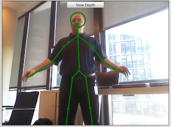
So, going back to your SkeletonDisplayManager, you now need to draw the skeletons inside the WPF canvas. To do so, you can add a list of circles that indicate where the joints are and then draw lines between the joints.
You can get access to a skeleton’s joints collection easily using the skeleton.Joints property. To draw all the detected and tracked skeletons in a frame, you simply cycle through the Skeletons array with the following code:
public void Draw(Skeleton[] skeletons)
{
rootCanvas.Children.Clear();
foreach (Skeleton skeleton in skeletons)
{
    if (skeleton.TrackingState != SkeletonTrackingState.Tracked)
        continue;

    Plot(JointType.HandLeft, skeleton.Joints);
    Trace(JointType.HandLeft, JointType.WristLeft, skeleton.Joints);
    Plot(JointType.WristLeft, skeleton.Joints);
    Trace(JointType.WristLeft, JointType.ElbowLeft, skeleton.Joints);
    Plot(JointType.ElbowLeft, skeleton.Joints);
    Trace(JointType.ElbowLeft, JointType.ShoulderLeft, skeleton.Joints);
    Plot(JointType.ShoulderLeft, skeleton.Joints);
    Trace(JointType.ShoulderLeft, JointType.ShoulderCenter, skeleton.Joints);
    Plot(JointType.ShoulderCenter, skeleton.Joints);

    Trace(JointType.ShoulderCenter, JointType.Head, skeleton.Joints);

    Plot(JointType.Head, JointType.ShoulderCenter, skeleton.Joints);

    Trace(JointType.ShoulderCenter, JointType.ShoulderRight, skeleton.Joints);
    Plot(JointType.ShoulderRight, skeleton.Joints);
    Trace(JointType.ShoulderRight, JointType.ElbowRight, skeleton.Joints);
    Plot(JointType.ElbowRight, skeleton.Joints);
    Trace(JointType.ElbowRight, JointType.WristRight, skeleton.Joints);
    Plot(JointType.WristRight, skeleton.Joints);
    Trace(JointType.WristRight, JointType.HandRight, skeleton.Joints);
    Plot(JointType.HandRight, skeleton.Joints);

    Trace(JointType.ShoulderCenter, JointType.Spine, skeleton.Joints);
    Plot(JointType.Spine, skeleton.Joints);
    Trace(JointType.Spine, JointType.HipCenter, skeleton.Joints);
    Plot(JointType.HipCenter, skeleton.Joints);

    Trace(JointType.HipCenter, JointType.HipLeft, skeleton.Joints);
    Plot(JointType.HipLeft, skeleton.Joints);
    Trace(JointType.HipLeft, JointType.KneeLeft, skeleton.Joints);
    Plot(JointType.KneeLeft, skeleton.Joints);
    Trace(JointType.KneeLeft, JointType.AnkleLeft, skeleton.Joints);
    Plot(JointType.AnkleLeft, skeleton.Joints);
    Trace(JointType.AnkleLeft, JointType.FootLeft, skeleton.Joints);
    Plot(JointType.FootLeft, skeleton.Joints);

    Trace(JointType.HipCenter, JointType.HipRight, skeleton.Joints);
    Plot(JointType.HipRight, skeleton.Joints);
    Trace(JointType.HipRight, JointType.KneeRight, skeleton.Joints);
    Plot(JointType.KneeRight, skeleton.Joints);
    Trace(JointType.KneeRight, JointType.AnkleRight, skeleton.Joints);
    Plot(JointType.AnkleRight, skeleton.Joints);
    Trace(JointType.AnkleRight, JointType.FootRight, skeleton.Joints);
    Plot(JointType.FootRight, skeleton.Joints);
}
}
The Trace and Plot methods search for a given joint through the Joints collection. The Trace method traces a line between two joints and then the Plot method draws a point where the joint belongs.
Before looking at these methods, you must add some more code to your project. First add a Vector2 class that represents a two-dimensional (2D) coordinate (x, y) with associated simple operators (+, -, *, etc.):
using System;

namespace Kinect.Toolbox
{
    [Serializable]
    public struct Vector2
    {
        public float X;
        public float Y;

        public static Vector2 Zero
        {
            get
            {
                return new Vector2(0, 0);
            }
        }

        public Vector2(float x, float y)
        {
            X = x;
            Y = y;
        }

        public float Length
        {
            get
            {
                return (float)Math.Sqrt(X * X + Y * Y);
            }
        }

        public static Vector2 operator -(Vector2 left, Vector2 right)
        {
            return new Vector2(left.X - right.X, left.Y - right.Y);
        }

        public static Vector2 operator +(Vector2 left, Vector2 right)
        {
            return new Vector2(left.X + right.X, left.Y + right.Y);
        }

        public static Vector2 operator *(Vector2 left, float value)
        {
            return new Vector2(left.X * value, left.Y * value);
        }

        public static Vector2 operator *(float value, Vector2 left)
        {
            return left * value;
        }

        public static Vector2 operator /(Vector2 left, float value)
        {
            return new Vector2(left.X / value, left.Y / value);
        }

    }

}
There is nothing special to note in the previous code; it is simple 2D math.
The second step involves converting the joint coordinates from skeleton space (x, y, z in meter units) to screen space (in pixel units). To do so, you can add a Convert method to your Tools class:
  public static Vector2 Convert(KinectSensor sensor, SkeletonPoint position)
        {
            float width = 0;
            float height = 0;
            float x = 0;
            float y = 0;

            if (sensor.ColorStream.IsEnabled)
            {
                var colorPoint = sensor.MapSkeletonPointToColor(position,
sensor.ColorStream.Format);
                x = colorPoint.X;
                y = colorPoint.Y;

                switch (sensor.ColorStream.Format)
                {
                    case ColorImageFormat.RawYuvResolution640x480Fps15:
                    case ColorImageFormat.RgbResolution640x480Fps30:
                    case ColorImageFormat.YuvResolution640x480Fps15:
                        width = 640;
                        height = 480;
                        break;
                    case ColorImageFormat.RgbResolution1280x960Fps12:
                        width = 1280;
                        height = 960;
                        break;
                }
            }
            else if (sensor.DepthStream.IsEnabled)
            {
                var depthPoint = sensor.MapSkeletonPointToDepth(position,
sensor.DepthStream.Format);
                x = depthPoint.X;
                y = depthPoint.Y;

                switch (sensor.DepthStream.Format)
                {
                    case DepthImageFormat.Resolution80x60Fps30:
                        width = 80;
                        height = 60;
                        break;
                    case DepthImageFormat.Resolution320x240Fps30:
                        width = 320;
                        height = 240;
                        break;
                    case DepthImageFormat.Resolution640x480Fps30:
                        width = 640;
                        height = 480;
                        break;
                }
            }
            else
            {
                width = 1;
                height = 1;
            }

            return new Vector2(x / width, y / height);
        }
The Convert method uses the Kinect for Windows SDK mapping API to convert from skeleton space to color or depth space. If the color stream is enabled, it will be used to map the coordinates using the kinectSensor.MapSkeletonPointToColor method, and using the color stream format, you can get the width and the height of the color space. If the color stream is disabled, the method uses the depth stream in the same way.
The method gets a coordinate (x, y) and a space size (width, height). Using this information, it returns a new Vector2 class with an absolute coordinate (a coordinate relative to a unary space).
Then you have to add a private method used to determine the coordinates of a joint inside the canvas to your SkeletonDisplayManager class:
void GetCoordinates(JointType jointType, IEnumerable<Joint> joints, out float x, out float y)
{
    var joint = joints.First(j => j.JointType == jointType);

    Vector2 vector2 = Convert(kinectSensor, joint.Position);

    x = (float)(vector2.X * rootCanvas.ActualWidth);
    y = (float)(vector2.Y * rootCanvas.ActualHeight);
}
With an absolute coordinate, it is easy to deduce the canvas space coordinate of the joint:
x = (float)(vector2.X * rootCanvas.ActualWidth);
y = (float)(vector2.Y * rootCanvas.ActualHeight);
Finally, with the help of the previous methods, the Plot and Trace methods are defined as follows:
void Plot(JointType centerID, IEnumerable<Joint> joints)
{
    float centerX;
    float centerY;

    GetCoordinates(centerID, joints, out centerX, out centerY);

    const double diameter = 8;

    Ellipse ellipse = new Ellipse
    {
        Width = diameter,
        Height = diameter,
        HorizontalAlignment = HorizontalAlignment.Left,
        VerticalAlignment = VerticalAlignment.Top,
        StrokeThickness = 4.0,
        Stroke = new SolidColorBrush(Colors.Green),
        StrokeLineJoin = PenLineJoin.Round
    };

    Canvas.SetLeft(ellipse, centerX - ellipse.Width / 2);
    Canvas.SetTop(ellipse, centerY - ellipse.Height / 2);

    rootCanvas.Children.Add(ellipse);
}

void Trace(JointType sourceID, JointType destinationID, JointCollection joints)
{
    float sourceX;
    float sourceY;

    GetCoordinates(sourceID, joints, out sourceX, out sourceY);

    float destinationX;
    float destinationY;

    GetCoordinates(destinationID, joints, out destinationX, out destinationY);

    Line line = new Line
                    {
                        X1 = sourceX,
                        Y1 = sourceY,
                        X2 = destinationX,
                        Y2 = destinationY,
                        HorizontalAlignment = HorizontalAlignment.Left,
                        VerticalAlignment = VerticalAlignment.Top,
                        StrokeThickness = 4.0,
                        Stroke = new SolidColorBrush(Colors.Green),
                        StrokeLineJoin = PenLineJoin.Round
                    };


    rootCanvas.Children.Add(line);
}
The main point to remember here is that WPF shapes (Line or Ellipse) are created to represent parts of the skeleton. After the shape is created, it is added to the canvas.
Note
The WPF shapes are recreated at every render. To optimize the display, it is better to keep the shapes and move them to the skeleton as needed, but that is a more complex process that is not required for the scope of this book.
The only specific joint in the skeleton is the head because it makes sense to draw it bigger than the other joints to represent the head of the skeleton. To do so, a new Plot method is defined:
void Plot(JointType centerID, JointType baseID, JointCollection joints)
{
    float centerX;
    float centerY;

    GetCoordinates(centerID, joints, out centerX, out centerY);

    float baseX;
    float baseY;

    GetCoordinates(baseID, joints, out baseX, out baseY);

    double diameter = Math.Abs(baseY - centerY);

    Ellipse ellipse = new Ellipse
    {
        Width = diameter,
        Height = diameter,
        HorizontalAlignment = HorizontalAlignment.Left,
        VerticalAlignment = VerticalAlignment.Top,
        StrokeThickness = 4.0,
        Stroke = new SolidColorBrush(Colors.Green),
        StrokeLineJoin = PenLineJoin.Round
    };

    Canvas.SetLeft(ellipse, centerX - ellipse.Width / 2);
    Canvas.SetTop(ellipse, centerY - ellipse.Height / 2);

    rootCanvas.Children.Add(ellipse);
}
In this case, the ellipse’s diameter is defined using the distance between the head and the center of shoulder.
Finally, you can also add a new parameter to the Draw method to support the seated mode. In this case, you must not draw the lower body joints:
public void Draw(Skeleton[] skeletons, bool seated)
{
    rootCanvas.Children.Clear();
    foreach (Skeleton skeleton in skeletons)
    {
        if (skeleton.TrackingState != SkeletonTrackingState.Tracked)
            continue;

        Plot(JointType.HandLeft, skeleton.Joints);
        Trace(JointType.HandLeft, JointType.WristLeft, skeleton.Joints);
        Plot(JointType.WristLeft, skeleton.Joints);
        Trace(JointType.WristLeft, JointType.ElbowLeft, skeleton.Joints);
        Plot(JointType.ElbowLeft, skeleton.Joints);
        Trace(JointType.ElbowLeft, JointType.ShoulderLeft, skeleton.Joints);
        Plot(JointType.ShoulderLeft, skeleton.Joints);
        Trace(JointType.ShoulderLeft, JointType.ShoulderCenter, skeleton.Joints);
        Plot(JointType.ShoulderCenter, skeleton.Joints);

        Trace(JointType.ShoulderCenter, JointType.Head, skeleton.Joints);

        Plot(JointType.Head, JointType.ShoulderCenter, skeleton.Joints);

        Trace(JointType.ShoulderCenter, JointType.ShoulderRight, skeleton.Joints);
        Plot(JointType.ShoulderRight, skeleton.Joints);
        Trace(JointType.ShoulderRight, JointType.ElbowRight, skeleton.Joints);
        Plot(JointType.ElbowRight, skeleton.Joints);
        Trace(JointType.ElbowRight, JointType.WristRight, skeleton.Joints);
        Plot(JointType.WristRight, skeleton.Joints);
        Trace(JointType.WristRight, JointType.HandRight, skeleton.Joints);
        Plot(JointType.HandRight, skeleton.Joints);

        if (!seated)
        {
            Trace(JointType.ShoulderCenter, JointType.Spine, skeleton.Joints);
            Plot(JointType.Spine, skeleton.Joints);
            Trace(JointType.Spine, JointType.HipCenter, skeleton.Joints);
            Plot(JointType.HipCenter, skeleton.Joints);

            Trace(JointType.HipCenter, JointType.HipLeft, skeleton.Joints);
            Plot(JointType.HipLeft, skeleton.Joints);
            Trace(JointType.HipLeft, JointType.KneeLeft, skeleton.Joints);
            Plot(JointType.KneeLeft, skeleton.Joints);
            Trace(JointType.KneeLeft, JointType.AnkleLeft, skeleton.Joints);
            Plot(JointType.AnkleLeft, skeleton.Joints);
            Trace(JointType.AnkleLeft, JointType.FootLeft, skeleton.Joints);
            Plot(JointType.FootLeft, skeleton.Joints);

            Trace(JointType.HipCenter, JointType.HipRight, skeleton.Joints);
            Plot(JointType.HipRight, skeleton.Joints);
            Trace(JointType.HipRight, JointType.KneeRight, skeleton.Joints);
            Plot(JointType.KneeRight, skeleton.Joints);
            Trace(JointType.KneeRight, JointType.AnkleRight, skeleton.Joints);
            Plot(JointType.AnkleRight, skeleton.Joints);
            Trace(JointType.AnkleRight, JointType.FootRight, skeleton.Joints);
            Plot(JointType.FootRight, skeleton.Joints);
        }
    }
}
The audio stream provides two important pieces of information that the user of your Kinect applications may want to know. The first is the sound source angle, which is the angle (in radians) to the current position of the audio source in camera coordinates.
The second is the beam angle produced by the microphone array. By using the fact that the sound from a particular audio source arrives at each microphone in the array at a slightly different time, beamforming allows applications to determine the direction of the audio source and use the microphone array as a steerable directional microphone.
The beam angle can be important as a visual feedback to indicate which audio source is being used (for speech recognition, for instance), as shown in Figure 3-6.
This visual feedback is a virtual representation of the sensor, and in Figure 3-6, the orange area to the right of center (which appears as gray in the print book) indicates the direction of the beam. (For readers of the print book, Figure 3-6 is orange near the center and fades to black on either side of the beam.)
To recreate the same control, you can add an XAML page with the following XAML declaration:
<Rectangle x:Name="audioBeamAngle" Height="20" Width="300" Margin="5">
    <Rectangle.Fill>
        <LinearGradientBrush StartPoint="0,0" EndPoint="1, 0">
            <GradientStopCollection>
                <GradientStop Offset="0" Color="Black"/>
                <GradientStop Offset="{Binding BeamAngle}" Color="Orange"/>
                <GradientStop Offset="1" Color="Black"/>
            </GradientStopCollection>
        </LinearGradientBrush>
    </Rectangle.Fill>
</Rectangle>
You can see that the rectangle is filled with a LinearGradientBrush starting from black to orange to black. The position of the orange GradientStop can be bound to a BeamAngle property exposed by a class.
The binding code itself is quite obvious:
var kinectSensor = KinectSensor.KinectSensors[0];
var audioManager = new AudioStreamManager(kinectSensor.AudioSource);
audioBeamAngle.DataContext = audioManager;
So you have to create an AudioStreamManager class that exposes a BeamAngle property. The class inherits from the Notifier class you created earlier in this chapter and implements IDisposable:
using Microsoft.Kinect;
public class AudioStreamManager : Notifier, IDisposable
{
    readonly KinectAudioSource audioSource;

    public AudioStreamManager(KinectAudioSource source)
    {
        audioSource = source;
        audioSource.BeamAngleChanged += audioSource_BeamAngleChanged;
    }

    void audioSource_BeamAngleChanged(object sender, BeamAngleChangedEventArgs e)
    {
        RaisePropertyChanged(()=>BeamAngle);
    }

    public double BeamAngle
    {
        get
        {
            return (audioSource.BeamAngle - KinectAudioSource.MinBeamAngle) /
(KinectAudioSource.MaxBeamAngle - KinectAudioSource.MinBeamAngle);
        }
    }

    public void Dispose()
    {
        audioSource.BeamAngleChanged -= audioSource_BeamAngleChanged;
    }
}
There is nothing special to note about this code, except to mention that the computation of the BeamAngle returns a value in the range [0, 1], which in turn will be used to set the offset of the orange GradientStop.
Now you can display all kinds of streams produced by the Kinect sensor to provide reliable visual feedback to the users of your applications.