© John C. Shovic 2021
J. C. ShovicRaspberry Pi IoT Projectshttps://doi.org/10.1007/978-1-4842-6911-4_2

2. Sensing Your IoT Environment

John C. Shovic1  
(1)
Spokane Valley, WA, USA
 

Chapter Goal: Build Your First IoT Device

Topics Covered in This Chapter:
  • Building an inexpensive IoT sensor device based on the ESP8266 and Arduino IDE

  • Setting up a simple self-organizing IoT sensor net

  • Reading I2C sensor (light and color) on the Arduino devices

  • Reading data from remote IoT sensors on the Raspberry Pi

  • Using the Raspberry Pi for monitoring and debugging

  • Displaying your data on the screen and on an iPad

In this chapter, we build our first IoT device. This simple design, a light-sensor swarm, is easy to build and illustrates a number of IoT principles including the following:
  • Distributed control

  • Self-organization

  • Passing information to the Internet

  • Swarm behavior

The LightSwarm architecture is a simple and flexible scheme for understanding the idea of an IoT project using many simple small computers and sensors with shared responsibility for control and reporting. Note that, in this swarm, communication with the Internet is handled by a Raspberry Pi. The swarm devices talk to each other, but not with the Internet. The Raspberry Pi is located on the same WiFi access point as the swarm, but could be located far away with some clever forwarding of packets through your WiFi router. In this case, since we have no computer security at all in this design (see Chapter 7 for information on making your IoT swarm and device more secure), we are sticking with the local network.

IoT Sensor Nets

One of the major uses of the IoT will be building nets and groups of sensors. Inexpensive sensing is just as big of a driver for the IoT as the development of inexpensive computers. The ability for a computer to sense its environment is the key to gathering information for analysis, action, or transmittal to the Internet. Sensor nets have been around in academia for many years, but now the dropping prices and availability of development tools are quickly moving sensor nets out to the mainstream. Whole industrial and academic conferences are now held on sensor nets [www.sensornets.org]. The market is exploding for these devices, and opportunities are huge for the creative person or group that can figure out how to make the sensor net that will truly drive consumer sales.

IoT Characterization of This Project

As I discussed in Chapter 1, the first thing to do to understand an IoT project is to look at our six different aspects of IoT. LightSwarm is a pretty simple project and can be broken down into the six components listed in Table 2-1.
Table 2-1

LightSwarm Characterization (CPLPFC)

Aspect

Rating

Comments

Communications

9

WiFi connection to the Internet – can do ad hoc mesh-type communication

Processor power

7

80MHz XTensa Harvard Architecture CPU, ~80KB data RAM/~35KB of instruction RAM/200K ROM

Local storage

6

4MB Flash (or 3MB file system!)

Power consumption

7

~200mA transmitting, ~60mA receiving, no WiFi ~15mA, standby ~1mA

Functionality

7

Partial Arduino support (limited GPIO/analog inputs)

Cost

9

< $10 and getting cheaper

Ratings are from 1 to 10, 1 being the least suitable for IoT and 10 being the most suitable for IoT applications.

This gives us a CPLPFC rating of 7.2. This is calculated by averaging all six values together with equal weighting. This way is great for learning and experimenting and could be deployed for some applications.

The ESP8266 is an impressive device having a built-in WiFi connection, a powerful CPU, and quite a bit of RAM and access to the Arduino libraries. It is inexpensive and will get cheaper as time goes on. It is a powerful device for prototyping IoT applications requiring medium levels of functionality.

How Does This Device Hook Up to the IoT?

The ESP8266 provides a WiFi transmitter/receiver, a TCP/IP stack, and firmware to support direction connections to a local WiFi access point that then can connect to the Internet. In this project, the ESP8266 will only be talking to devices on the local wireless network. This is an amazing amount of functionality for less than $10 retail. These chips can be found for as little as $1 on the open market, if you want to roll your own printed circuit board.

What Is an ESP8266?

The ESP8266 is made by a company in China called Espressif [espressif.com]. They are a fabless semiconductor company that just came out of nowhere with the first generation of this chip and shook up the whole industry. Now all the major players are working on inexpensive versions of an IoT chip with WiFi connectivity. Why did we not use the more powerful ESP32? Two reasons, the ESP32 has way more CPU power than we need, and it is twice as expensive.

The ESP8266 chip was originally designed for connected light bulbs but soon got used in a variety of applications, and ESP8266 modules are currently now the most popular solutions to add WiFi to IoT projects. While the ESP8266 has huge functionality and a good price, the amount of current consumed by the chip makes battery-powered solutions problematic.

The ESP8266 is enabling a whole new set of applications and communities with their innovative and inexpensive design (Figure 2-1).
../images/367492_2_En_2_Chapter/367492_2_En_2_Fig1_HTML.jpg
Figure 2-1

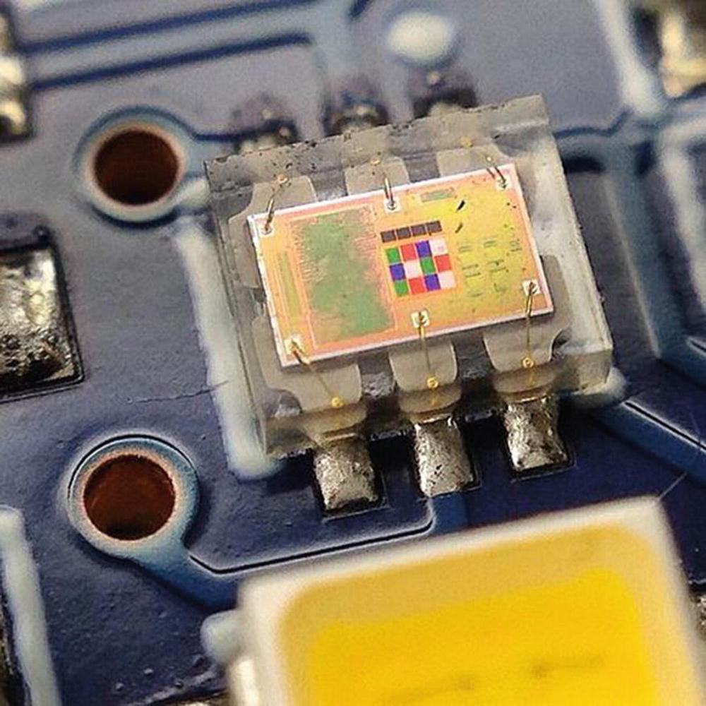
The ESP8266 Die (Courtesy of Hackaday.io)

We will be using a version of the ESP8266 on a breakout board designed by Adafruit (Figure 2-2). The board provides some connections, a built-in antenna, and some power regulation, all for less than $10.
../images/367492_2_En_2_Chapter/367492_2_En_2_Fig2_HTML.jpg
Figure 2-2

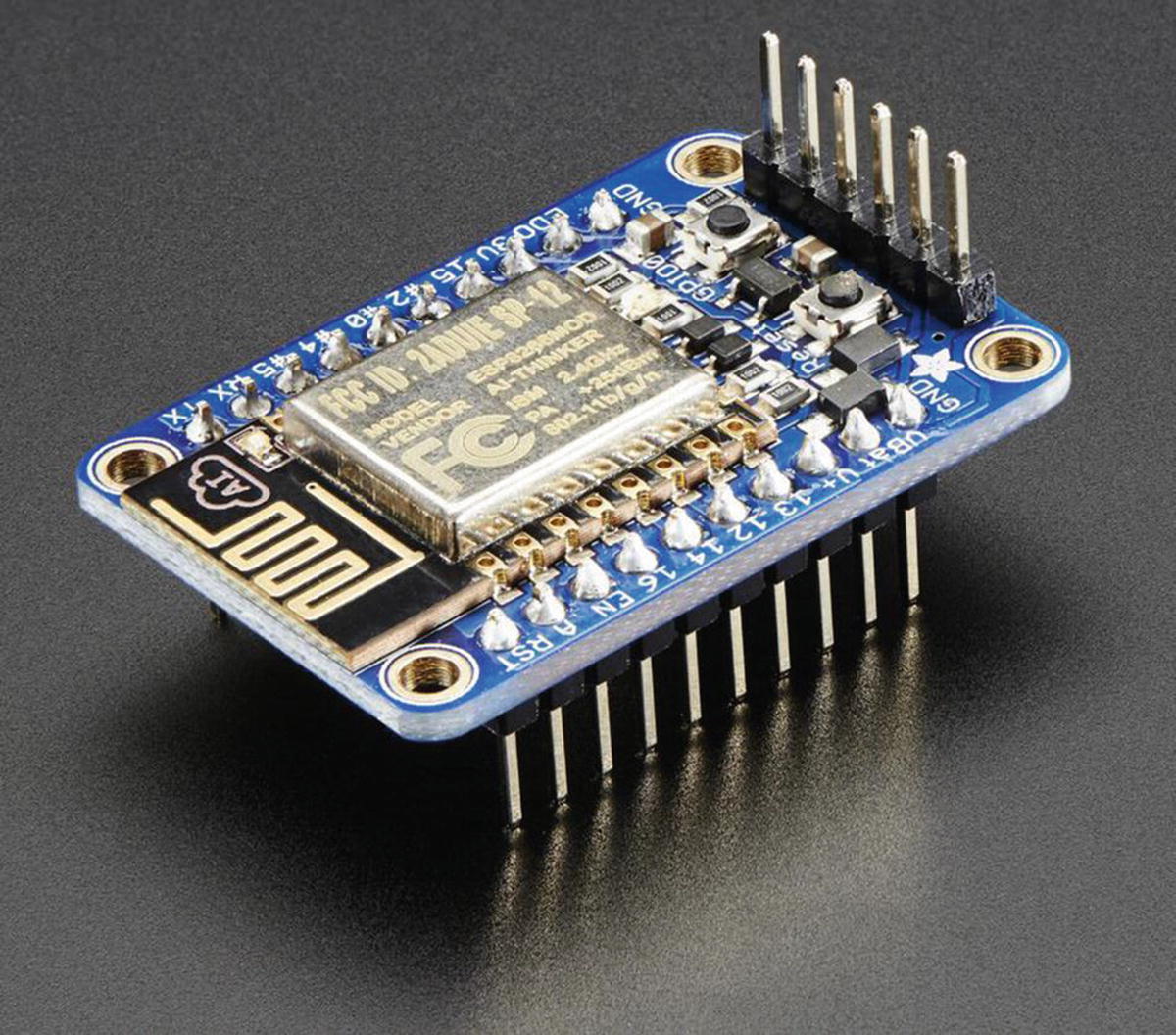
The Adafruit Huzzah ESP8266 (Courtesy of adafruit.com)

The LightSwarm Design

There are two major design aspects of the LightSwarm project . First of all, each element of the swarm is based on an ESP8266 with a light sensor attached. The software is what makes this small IoT device into a swarm. In the following block diagram, you can see the major two devices. I am using the Adafruit Huzzah breakout board for the ESP8266 [www.adafruit.com/product/2471]. Why use a breakout board? With a breakout board, you can quickly prototype devices and then move to a less expensive design in the future. The other electronic component (Figure 2-3) is a TCS34725 RGB light-sensor breakout board, also from Adafruit [www.adafruit.com/products/1334].
../images/367492_2_En_2_Chapter/367492_2_En_2_Fig3_HTML.jpg
Figure 2-3

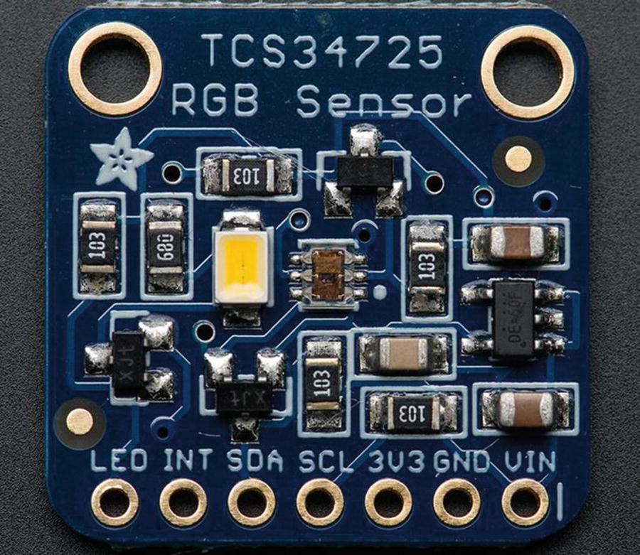
TCS34725 Breakout Board (Courtesy of adafruit.com)

The addition of a sensor to a computer is what makes this project an IoT device. I am sensing the environment and then doing something with the information (determining which of the Swarm has the brightest light). Figure 2-4 shows the block diagram of a single Swarm element.
../images/367492_2_En_2_Chapter/367492_2_En_2_Fig4_HTML.jpg
Figure 2-4

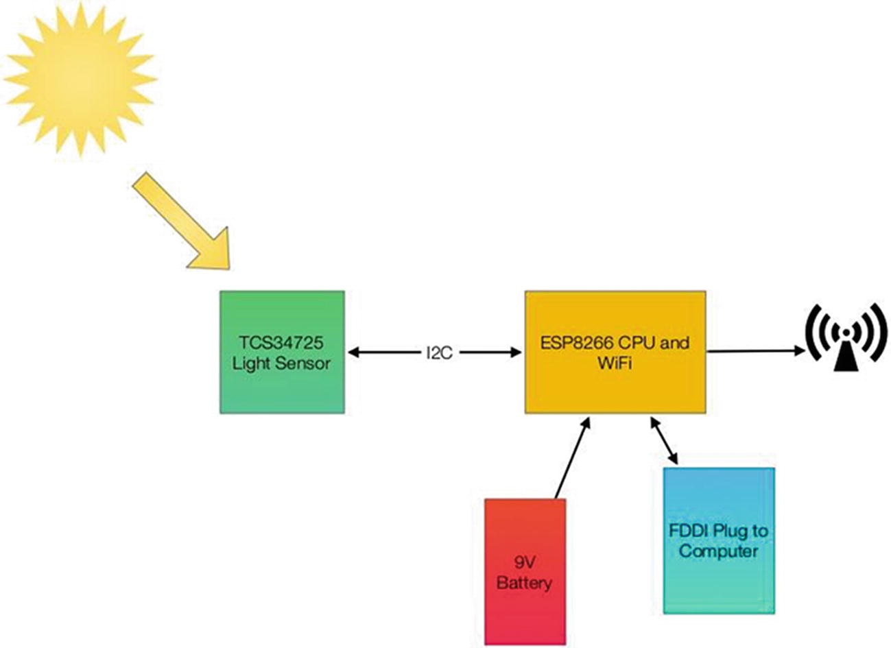
LightSwarm Element Block Diagram

Each of the LightSwarm devices in the swarm is identical. There are no software differences and no hardware differences. As you will see when we discuss the software, they vote with each other and compare notes and then elect the device that has the brightest light as the “Master,” and then the “Master” turns the red LED on the device to show us who has been elected “Master.” The swarm is designed so devices can drop out of the swarm, be added to the swarm dynamically, and the swarm adjusts to the new configuration. The swarm behavior (who is the master, how long it takes information about changing lights to propagate through the swarm, etc.) is rather complex. More complex than expected from the simple swarm device code. There is a lesson here: simple machines in groups can lead to large complex systems with higher-level behaviors based on the simple machines and the way they interact.

The behavior of the LightSwarm surprised me a number of times, and it was sometimes very difficult to figure out what was happening, even with the Raspberry Pi logger. Figure 2-5 shows the complete LightSwarm including the Raspberry Pi.
../images/367492_2_En_2_Chapter/367492_2_En_2_Fig5_HTML.jpg
Figure 2-5

The LightSwarm

The Raspberry Pi in this diagram is not controlling the swarm. The Raspberry Pi gathers data from the swarm (the current “Master” device sends information to the Raspberry Pi), and then the Raspberry Pi can store the data and communicate it through the Internet, in this case to a local web page.

The LightSwarm project has an amazing amount of functionality and quirky self-organizing behavior for such a simple design.

Building Your First IoT Swarm

Table 2-2 lists the parts needed to build an IoT Swarm.
Table 2-2

Swarm Parts List

Part Number

Count

Description

Approximate Cost per Board

Source

ESP8266 Huzzah board

5

CPU/WiFi board

$18

https://amzn.to/34VEgxJ

TCS34725 breakout board

5

I2C light sensor

$10

https://amzn.to/3n3fAt4

FTDI cable

1

Cable for programming the ESP8266 from PC/Mac

$20

https://amzn.to/34VEgxJ

Installing Arduino Support on the PC or Mac

The key to making this project work is the software. While there are many ways of programming the ESP8266 (MicroPython [micropython.org], NodeMCU Lua interpreter [nodemcu.com/index_en.html], and the Arduino IDE (Integrated Development Environment) [www.arduino.cc/en/Main/Software]), I chose the Arduino IDE for its flexibility and the large number of sensor and device libraries available.

To install the Arduino IDE, you need to do the following:
  1. a.

    Download the Arduino IDE package for your computer and install the software [www.arduino.cc/en/Guide/HomePage].

     
  2. b.

    Download the ESP libraries so you can use the Arduino IDE with the ESP breakout board. Adafruit has an excellent tutorial for installing the ESP8266 support for the Arduino IDE [learn.adafruit.com/adafruit-huzzah-esp8266-breakout/using-arduino-ide].


Your First Sketch for the ESP8266

A great way of testing your setup is to run a small sketch that will blink the red LED on the ESP8266 breakout board. The red LED is hooked up to GPIO 0 (General-Purpose Input/Output pin 0) on the Adafruit board.

Open a new sketch using the Arduino IDE and place the following code into the code window, replacing the stubs provided when opening a new sketch. The code given here will make the red LED blink:
void setup() {
  pinMode(0, OUTPUT);
}
void loop() {
  digitalWrite(0, HIGH);
  delay(500);
  digitalWrite(0, LOW);
  delay(500);
}

If your LED is happily blinking away now, you have correctly followed all the tutorials and have the ESP8266 and the Arduino IDE running on your computer.

Next, I will describe the major hardware systems and then dive into the software.

The Hardware

The main pieces of hardware in the swarm device are the following:
  • ESP8266 – CPU/WiFi interface Huzzah

  • TCS34725 – Light sensor

  • 9V battery power

  • FTDI cable – Programming and power

The ESP8266 communicates with other swarm devices by using the WiFi interface. The ESP8266 uses the I2C interface to communicate with the light sensor. The WiFi is a standard that is very common (although we use protocols to communicate that are not common). See the description of UDP (User Datagram Protocol) later in this chapter. The I2C bus interface is much less familiar and needs some explanation.

Reviewing the I2C Bus

An I2C bus is often used to communicate with chips or sensors that are on the same board or located physically close to the CPU. It stands for standard Inter-IC device bus . The I2C was first developed by Philips (now NXP Semiconductors). To get around licensing issues, often the bus will be called TWI (Two-Wire Interface). SMBus, developed by Intel, is a subset of I2C that defines the protocols more strictly. Modern I2C systems take policies and rules from SMBus sometimes supporting both with minimal reconfiguration needed. The Raspberry Pi and the Arduino are both these kinds of devices. Even the ESP8266 used in this project can support both.

An I2C provides good support for slow, close peripheral devices that only need be addressed occasionally. For example, a temperature measuring device will generally only change very slowly and so is a good candidate for the use of I2C, where a camera will generate lots of data quickly and potentially changes often.

An I2C bus uses only two bidirectional open-drain lines (open-drain means the device can pull a level down to ground, but cannot pull the line up to Vdd, hence the name open-drain). Thus, a requirement of an I2C bus is that both lines are pulled up to Vdd. This is an important area, and not properly pulling up the lines is the first and most common mistake you make when you first use an I2C bus. More on pullup resistors later in the next section. The two lines are SDA (Serial Data Line) and the SCL (Serial Clock Line). There are two types of devices you can connect to an I2C bus. They are Master devices and Slave devices. Typically, you have one Master device (the Raspberry Pi in our case) and multiple Slave devices, each with their individual 7-bit address (like 0x68 in the case of the DS1307). There are ways to have 10-bit addresses and multiple Master devices, but that is beyond the scope of this book. Figure 2-6 shows an I2C bus with devices and the master connected.
../images/367492_2_En_2_Chapter/367492_2_En_2_Fig6_HTML.jpg
Figure 2-6

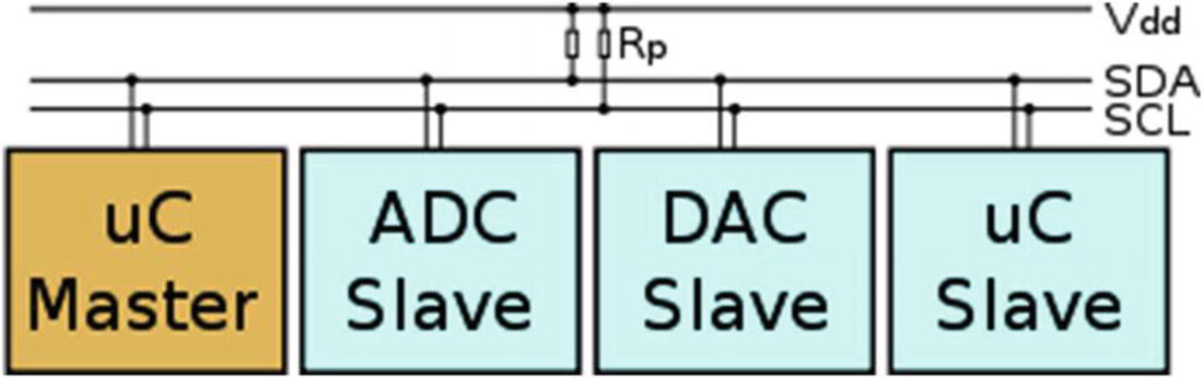
An I2C Bus with One Master (the ESP8266 in This Case) and Three Slave Devices. Rps Are the Pullup Resistors

SwitchDoc Note

Vcc and Vdd mean the same. Gnd and Vss generally also both mean ground. There are historical differences, but today Vcc usually is one power supply, and if there is a second, they will call it Vdd.

When used on the Raspberry Pi, the Raspberry Pi acts as the Master and all other devices are connected as Slaves.

SwitchDoc Note

If you connect an Arduino to a Raspberry Pi, you need to be careful about voltage levels because the Raspberry Pi is a 3.3V device and the Arduino is a 5.0V device. The ESP8266 is a 3.3V device so you also need to be careful connecting an Arduino to an ESP8266. Before you do this, read this excellent tutorial [blog.retep.org/2014/02/15/connecting-an-arduino-to-a-raspberry-pi-using-i2c/].

The I2C protocol uses three types of messages:
  • Single message where a master writes data to a slave

  • Single message where a master reads data from a slave

  • Combined messages, where a master issues at least two reads and/or writes to one or more slaves

Lucky for us, most of the complexity of dealing with the I2C bus is hidden by drivers and libraries.

Pullups on the I2C Bus

One important thing to consider on your I2C bus is a pullup resistor. The Raspberry Pi has 1.8K (1k8) ohm resistors already attached to the SDA and SCL lines, so you really shouldn't need any additional pullup resistors. However, you do need to look at your I2C boards to find out if they have pullup resistors. If you have too many devices on the I2C bus with their own pullups, your bus will stop working. The rule of thumb from Philips is not to let the total pullup resistors in parallel be less than 1K (1k0) ohms. You can get a pretty good idea of what the total pullup resistance is by turning the power off on all devices and using an ohm meter to measure the resistance on the SCL line from the SCL line to Vdd.

Sensor Being Used

We are using the TCS34725, which has RGB and clear light-sensing elements. Figure 2-7 shows the TCS34725 die with the optical sensor showing in the center of the figure. An IR blocking filter, integrated on-chip and localized to the color-sensing photodiodes, minimizes the IR spectral component of the incoming light and allows color measurements to be made accurately. The IR filter means you'll get much truer color than most sensors, since humans don't see IR. The sensor does see IR and thus the IR filter is provided. The sensor also has a 3,800,000:1 dynamic range with adjustable integration time and gain so it is suited for use behind darkened glass or directly in the light.
../images/367492_2_En_2_Chapter/367492_2_En_2_Fig7_HTML.jpg
Figure 2-7

The TCS34725 Chip Die

This is an excellent inexpensive sensor ($8 retail from Adafruit on a breakout board) and forms the basis of our IoT sensor array. Of course, you could add many more sensors, but having one sensor that is easy to manipulate is perfect for our first IoT project. In Chapter 3, we add many more sensors to the Raspberry Pi computer for a complete IoT Weather Station design.

3D Printed Case

One of the big changes in the way people build prototypes is the availability of inexpensive 3D printers. It used to be difficult to build prototype cases and stands for various electronic projects. Now it is easy to design a case in one of many types of 3D software and then print it out using your 3D printer. For the swarm, I wanted a partial case to hold the 9V battery, the ESP8266, and the light sensor. I used OpenSCAD [www.openscad.org] to do the design. OpenSCAD is a free 3D CAD system that appeals to programmers. Rather than doing the entire design in a graphical environment, you write code (consisting of various objects, joined together or subtracted from each other) that you then compile in the environment to form a design in 3D space. OpenSCAD comes with an IDE (Integrated Development Environment), and you place the code showing in Listing 2-1 in the editor, compile the code, and then see the results in the attached IDE as shown in Figure 2-8.
../images/367492_2_En_2_Chapter/367492_2_En_2_Fig8_HTML.jpg
Figure 2-8

OpenSCAD Display

As shown in Listing 2-1, the OpenSCAD programming code to build this stand is quite simple. It consists of cubes and cylinders of various sizes and types.
//
// IOT Light Swarm Mounting Base
//
// SwitchDoc Labs
// December 2020
//
union()
{
    cube([80,60,3]);
    translate([-1,-1,0])
    cube([82,62,2]);
    // Mount for Battery
    translate([40,2,0])
    cube([40,1.35,20]);
    translate([40,26.10+3.3,0])
    cube([40,1.5,20]);
    // lips for battery
    translate([79,2,0])
    cube([1,28,4]);
    // pylons for ESP8266
    translate([70-1.0,35,0])
    cylinder(h=10,r1=2.2, r2=1.35/2, $fn=100);
    translate([70-1.0,56,0])
    cylinder(h=10,r1=2.2, r2=1.35/2, $fn=100);
    translate([70-34,35,0])
    cylinder(h=10,r1=2.2, r2=1.35/2, $fn=100);
    translate([70-34,56,0])
    cylinder(h=10,r1=2.2, r2=1.35/2, $fn=100);
    // pylons for light sensor
    translate([10,35,0])
    cylinder(h=10,r1=2.2, r2=1.35/2, $fn=100);
    translate([10,49.5,0])
    cylinder(h=10,r1=2.2, r2=1.35/2, $fn=100);
   translate([22,37,0])
    cylinder(h=6,r1=2.2, r2=2.2, $fn=100);
    translate([22,47,0])
    cylinder(h=6,r1=2.2, r2=2.2, $fn=100);
}
Listing 2-1

Mounting Base for the IoT LightSwarm

You can see the completed stand and the FTDI cable in Figure 2-9. Once designed, I quickly built five of them for the LightSwarm. Figure 2-10 shows a completed Swarm element. You can print your own from the STL file.
../images/367492_2_En_2_Chapter/367492_2_En_2_Fig9_HTML.jpg
Figure 2-9

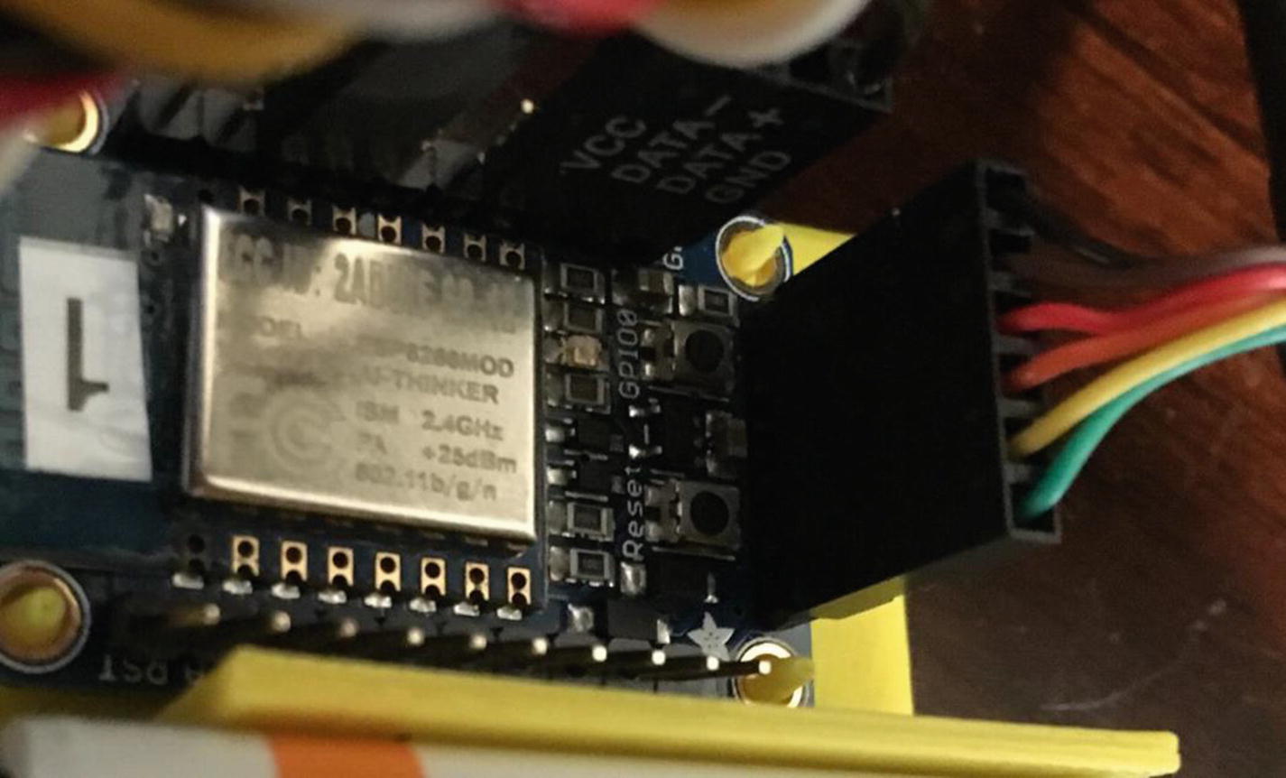
FTDI Cable Plugged into ESP8266

../images/367492_2_En_2_Chapter/367492_2_En_2_Fig10_HTML.jpg
Figure 2-10

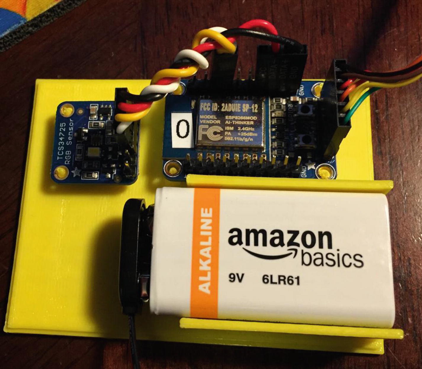
Completed LightSwarm Stand

You can download the STL file for the LightSwarm base from github/switchdoclabs.

Use this command:
git clone https://github.com/switchdoclabs/SDL_STL_LightSwarm.git

The Full Wiring List

Table 2-3 provides the complete wiring list for a LightSwarm device. As you wire it, check off each wire for accuracy.
Table 2-3

LightSwarm Wiring List

From

To

Description

ESP8266/GND

TCS34725/GND

Ground for I2C light sensor

ESP8266/3V

TCS34725/3V3

3.3V power for I2C light sensor

ESP8266/#4

TCS34725/SDA

SDA for I2C light sensor

ESP8266/#5

TCS34725/SCL

SCL for I2C light sensor

ESP8266/GND

9VBat/“-” terminal (minus terminal)

Ground for battery

ESP8266/VBat

9VBat/“+” terminal (plus 9V)

9V from battery

The FTDI cable is plugged into the end of the Adafruit Huzzah ESP8266. Make sure you align the black wire with the GND pin on the ESP8266 breakout board as in Figure 2-9. Figure 2-11 shows the fully complete LightSwarm device.
../images/367492_2_En_2_Chapter/367492_2_En_2_Fig11_HTML.jpg
Figure 2-11

A Complete LightSwarm Device

The Software

There are two major modules written for the LightSwarm. The first is ESP8266 code for the LightSwarm device itself (written in the Arduino IDE – in simplified C and C++ language), and the second is the Raspberry Pi data-gathering software (written in Python3 on the Raspberry Pi). There is an excellent tutorial on how to set up the Arduino IDE and the ESP8266 libraries at https://learn.adafruit.com/adafruit-huzzah-esp8266-breakout.

The major design specifications for the LightSwarm device software are the following:
  • Device self-discovery.

  • Device becomes master when it has the brightest light; all others become slaves.

  • Distributed voting method for determining master status.

  • Self-organizing swarm. No server.

  • Swarm must survive and recover from devices coming in and out of the network.

  • Master device sends data to Raspberry Pi for analysis and distribution to the Internet.

The entire code for the LightSwarm devices is provided in Listings 2-2 through 2-11 (with the exception of the TCS74725 light-sensor driver, available here: github.com/adafruit/Adafruit_TCS34725). The latest code is also available on the Apress website [www.apress.com] and the SwitchDoc Labs github site [github.com/switchdoclabs/SDL_ESP8266_LightSwarm]. Listing 2-2 shows the beginning includes and the inital defines for parameters.
/*
Cooperative IOT Self Organizing Example
SwitchDoc Labs, December 2020
 */
#include <ESP8266WiFi.h>
#include <WiFiUdp.h>
#include <Wire.h>
#include "Adafruit_TCS34725.h"
#undef DEBUG
char ssid[] = "yyyyy";         // your wireless network SSID (name)
char pass[] = "xxxxxxx";       // your wireless network password
#define VERSIONNUMBER 28
#define SWARMSIZE 5
// 30 seconds is too old - it must be dead
#define SWARMTOOOLD 30000
int mySwarmID = 0;
Listing 2-2

LightSwarm Code

Next in Listing 2-3, we define the necessary constants. Here are the definitions of all the Swarm commands available:
  • LIGHT_UPDATE_PACKET – Packet containing current light from a LightSwarm device. Used to determine who is master and who is slave.

  • RESET_SWARM_PACKET – All LightSwarm devices are told to reset their software.

  • CHANGE_TEST_PACKET – Designed to change the master/slave criteria (not implemented).

  • RESET_ME_PACKET – Just reset a particular LightSwarm device ID.

  • DEFINE_SERVER_LOGGER_PACKET – This is the new IP address of the Raspberry Pi so the LightSwarm device can send data packets.

  • LOG_TO_SERVER_PACKET – Packets sent from LightSwarm devices to Raspberry Pi.

  • MASTER_CHANGE_PACKET – Packet sent from LightSwarm device when it becomes a master (not implemented).

  • BLINK_BRIGHT_LED – Command to a LightSwarm device to blink the bright LED on the TCS34725.

After the constants in Listing 2-3, I set up the system variables for the devices. I am using UDP across the WiFi interface. What is UDP? UDP stands for User Datagram Protocol. UDP uses a simple connectionless model. Connectionless means that there is no handshake between the transmitting device and the receiving device to let the transmitter know that the receiver is actually there. Unlike TCP (Transmission Control Protocol), you have no idea or guarantee of data packets being delivered to any particular device. You can think of it as kind of a TV broadcast to your local network. Everyone gets it, but they don’t have to read the packets. There are also subtle other effects – such as you don’t have any guarantee that packets will arrive in the order they are sent. So why are we using UDP instead of TCP? I am using the broadcast mode of UDP so when a LightSwarm device sends out a message to the WiFi subnet, everybody gets it, and if they are listening on the port 2910 (set previously), then they can react to the message. This is how LightSwarm devices get discovered. Everybody starts sending packages (with random delays introduced), and all of the LightSwarm devices figure out who is present and who has the brightest light. Nothing in the LightSwarm system assigns IP numbers or names. They all figure it out themselves.
// Packet Types
#define LIGHT_UPDATE_PACKET 0
#define RESET_SWARM_PACKET 1
#define CHANGE_TEST_PACKET 2
#define RESET_ME_PACKET 3
#define DEFINE_SERVER_LOGGER_PACKET 4
#define LOG_TO_SERVER_PACKET 5
#define MASTER_CHANGE_PACKET 6
#define BLINK_BRIGHT_LED 7
unsigned int localPort = 2910;      // local port to listen for UDP packets
// master variables
boolean masterState = true;   // True if master, False if not
int swarmClear[SWARMSIZE];
int swarmVersion[SWARMSIZE];
int swarmState[SWARMSIZE];
long swarmTimeStamp[SWARMSIZE];   // for aging
IPAddress serverAddress = IPAddress(0, 0, 0, 0); // default no IP Address
int swarmAddresses[SWARMSIZE];  // Swarm addresses
// variables for light sensor
int clearColor;
int redColor;
int blueColor;
int greenColor;
const int PACKET_SIZE = 14; // Light Update Packet
const int BUFFERSIZE = 1024;
byte packetBuffer[BUFFERSIZE]; //buffer to hold incoming and outgoing packets
// A UDP instance to let us send and receive packets over UDP
WiFiUDP udp;
/* Initialize with specific int time and gain values */
Adafruit_TCS34725 tcs = Adafruit_TCS34725(TCS34725_INTEGRATIONTIME_700MS, TCS34725_GAIN_1X);
IPAddress localIP;
Listing 2-3

LightSwarm Constants

The setup() routine shown in Listing 2-4 is only run once after reset of the ESP8266 and is used to set up all the devices and print logging information to the serial port on the ESP8266, where, if you have the FTDI cable connected, you can see the logging information and debugging information on your PC or Mac.
void setup()
{
  Serial.begin(115200);
  Serial.println();
  Serial.println();
  Serial.println("");
  Serial.println("--------------------------");
  Serial.println("LightSwarm");
  Serial.print("Version ");
  Serial.println(VERSIONNUMBER);
  Serial.println("--------------------------");
  Serial.println(F(" 09/03/2015"));
  Serial.print(F("Compiled at:"));
  Serial.print (F(__TIME__));
  Serial.print(F(" "));
  Serial.println(F(__DATE__));
  Serial.println();
  pinMode(0, OUTPUT);
  digitalWrite(0, LOW);
  delay(500);
  digitalWrite(0, HIGH);
Listing 2-4

The setup() Function for LightSwarm

Here, we use the floating value of the analog input on the ESP8266 to set the pseudo-random number generation seed. This will vary a bit from device to device, and so it’s not a bad way of initializing the pseudo-random number generator. If you put a fixed number as the argument, it will always generate the same set of pseudo-random numbers. This can be very useful in testing. Listing 2-5 shows the setup of the random seed and the detection of the TCS34725.

What is a pseudo-random number generator? It is an algorithm for generating a sequence of numbers whose properties approximate a truly random number sequence. It is not a truly random sequence of numbers, but it is close. Good enough for our usage.
randomSeed(analogRead(A0));
  Serial.print("analogRead(A0)=");
  Serial.println(analogRead(A0));
  if (tcs.begin()) {
    Serial.println("Found sensor");
  } else {
    Serial.println("No TCS34725 found ... check your connections");
  }
  // turn off the light
  tcs.setInterrupt(true);  // true means off, false means on
  // everybody starts at 0 and changes from there
  mySwarmID = 0;
  // We start by connecting to a WiFi network
  Serial.print("LightSwarm Instance: ");
  Serial.println(mySwarmID);
  Serial.print("Connecting to ");
  Serial.println(ssid);
  WiFi.begin(ssid, pass);
  // initialize Swarm Address - we start out as swarmID of 0
  while (WiFi.status() != WL_CONNECTED) {
    delay(500);
    Serial.print(".");
  }
  Serial.println("");
  Serial.println("WiFi connected");
  Serial.println("IP address: ");
  Serial.println(WiFi.localIP());
  Serial.println("Starting UDP");
  udp.begin(localPort);
  Serial.print("Local port: ");
  Serial.println(udp.localPort());
  // initialize light sensor and arrays
  int i;
  for (i = 0; i < SWARMSIZE; i++)
  {
    swarmAddresses[i] = 0;
    swarmClear[i] = 0;
    swarmTimeStamp[i] = -1;
  }
  swarmClear[mySwarmID] = 0;
  swarmTimeStamp[mySwarmID] = 1;   // I am always in time to myself
  clearColor = swarmClear[mySwarmID];
  swarmVersion[mySwarmID] = VERSIONNUMBER;
  swarmState[mySwarmID] = masterState;
  Serial.print("clearColor =");
  Serial.println(clearColor);
Listing 2-5

Remainder of the setup() Function for LightSwarm

Now we have initialized all the data structures for describing our LightSwarm device and the states of the light sensor. Listing 2-6 sets the SwarmID based on the current device IP address. When you turn on a LightSwarm device and it connects to a WiFi access point, the access point assigns a unique IP address to the LightSwarm device. This is done through a process called DHCP (Dynamic Host Configuration Protocol) [en.wikipedia.org/wiki/Dynamic_Host_Configuration_Protocol]. While the number will be different for each LightSwarm device, it is not random. Typically, if you power a specific device down and power it up again, the access point will assign the same IP address. However, you can’t count on this. The access point knows your specific device because each and every WiFi interface has a specific and unique MAC (Media Access Control) number, which is usually never changed.

SwitchDoc Note

Faking MAC addresses allows you to impersonate other devices with your device in some cases, and you can use MAC addresses to track specific machines by looking at the network. This is why Apple Inc. has started using random MAC addresses in their devices while scanning for networks. If random MAC addresses aren’t used, then researchers have confirmed that it is possible to link a specific real identity to a particular wireless MAC address [Cunche, Mathieu. “I know your MAC Address: Targeted tracking of individual using Wi-Fi”. 2013].

  // set SwarmID based on IP address
  localIP = WiFi.localIP();
  swarmAddresses[0] =  localIP[3];
  mySwarmID = 0;
  Serial.print("MySwarmID=");
  Serial.println(mySwarmID);
}
Listing 2-6

Setting the SwarmID from IP Address

The second main section of the LightSwarm device code is the loop(). The loop() function does precisely what its name suggests and loops infinitely, allowing your program to change and respond. This is the section of the code that performs the main work of the LightSwarm code.
void loop()
{
  int secondsCount;
  int lastSecondsCount;
  lastSecondsCount = 0;
 #define LOGHOWOFTEN
  secondsCount = millis() / 100;

In Listing 2-7, we read all the data from the TCS34725 sensor to find out how bright the ambient light currently is. This forms the substance of the data to determine who the master in the swarm is.

After the delay (300) line in Listing 2-7, I check for UDP packets being broadcast to port 2910. Remember the way the swarm is using UDP is in broadcast mode and all packets are being received by everybody all the time. Note, this sets a limit of how many swarm devices you can have (limited to the subnet size) and also by the congestion of having too many messages go through at the same time. This was pretty easy to simulate by increasing the rate that packets are sent. The swarm still functions, but the behavior becomes more erratic and with sometimes large delays.
uint16_t r, g, b, c, colorTemp, lux;
tcs.getRawData(&r, &g, &b, &c);
colorTemp = tcs.calculateColorTemperature(r, g, b);
lux = tcs.calculateLux(r, g, b);
Serial.print("Color Temp: "); Serial.print(colorTemp, DEC); Serial.print(" K - ");
Serial.print("Lux: "); Serial.print(lux, DEC); Serial.print(" - ");
Serial.print("R: "); Serial.print(r, DEC); Serial.print(" ");
Serial.print("G: "); Serial.print(g, DEC); Serial.print(" ");
Serial.print("B: "); Serial.print(b, DEC); Serial.print(" ");
Serial.print("C: "); Serial.print(c, DEC); Serial.print(" ");
Serial.println(" ");
clearColor = c;
redColor = r;
blueColor = b;
greenColor = g;
swarmClear[mySwarmID] = clearColor;
// wait to see if a reply is available
delay(300);
int cb = udp.parsePacket();
if (!cb) {
  //  Serial.println("no packet yet");
  Serial.print(".");
}
else {
Listing 2-7

Reading the Light Color

In Listing 2-8, we interpret all the packets depending on the packet type.
// We've received a packet, read the data from it
   udp.read(packetBuffer, PACKET_SIZE); // read the packet into the buffer
   Serial.print("packetbuffer[1] =");
   Serial.println(packetBuffer[1]);
   if (packetBuffer[1] == LIGHT_UPDATE_PACKET)
   {
     Serial.print("LIGHT_UPDATE_PACKET received from LightSwarm #");
     Serial.println(packetBuffer[2]);
     setAndReturnMySwarmIndex(packetBuffer[2]);
     Serial.print("LS Packet Recieved from #");
     Serial.print(packetBuffer[2]);
     Serial.print(" SwarmState:");
     if (packetBuffer[3] == 0)
       Serial.print("SLAVE");
     else
       Serial.print("MASTER");
     Serial.print(" CC:");
     Serial.print(packetBuffer[5] * 256 + packetBuffer[6]);
     Serial.print(" RC:");
     Serial.print(packetBuffer[7] * 256 + packetBuffer[8]);
     Serial.print(" GC:");
     Serial.print(packetBuffer[9] * 256 + packetBuffer[10]);
     Serial.print(" BC:");
     Serial.print(packetBuffer[11] * 256 + packetBuffer[12]);
     Serial.print(" Version=");
     Serial.println(packetBuffer[4]);
     // record the incoming clear color
     swarmClear[setAndReturnMySwarmIndex(packetBuffer[2])] = packetBuffer[5] * 256 + packetBuffer[6];
     swarmVersion[setAndReturnMySwarmIndex(packetBuffer[2])] = packetBuffer[4];
     swarmState[setAndReturnMySwarmIndex(packetBuffer[2])] = packetBuffer[3];
     swarmTimeStamp[setAndReturnMySwarmIndex(packetBuffer[2])] = millis();
     // Check to see if I am master!
     checkAndSetIfMaster();
   }
Listing 2-8

Interpreting the Packet Type

The RESET_SWARM_PACKET command sets all of the LightSwarm devices to master (turning on the red LED on each) and then lets the LightSwarm software vote and determine who has the brightest light. As each device receives a LIGHT_UPDATE_PACKET, it compares the light from that swarm device to its own sensor and becomes a slave if their light is brighter. Eventually, the swarm figures out who has the brightest light. I have been sending this periodically from the Raspberry Pi and watching the devices work it out. It makes an interesting video. Listing 2-9 shows how LightSwarm interprets incoming packets. The very last section of Listing 2-9 shows how the Swarm element updates everybody else in the Swarm what is going on with this device, and then we send a data packet to the Raspberry Pi if we are the swarm master.
if (packetBuffer[1] == RESET_SWARM_PACKET)
{
  Serial.println(">>>>>>>>>RESET_SWARM_PACKETPacket Received");
  masterState = true;
  Serial.println("Reset Swarm:  I just BECAME Master (and everybody else!)");
  digitalWrite(0, LOW);
}
if (packetBuffer[1] == CHANGE_TEST_PACKET)
{
  Serial.println(">>>>>>>>>CHANGE_TEST_PACKET Packet Received");
  Serial.println("not implemented");
  int i;
  for (i = 0; i < PACKET_SIZE; i++)
  {
    if (i == 2)
    {
      Serial.print("LPS[");
      Serial.print(i);
      Serial.print("] = ");
      Serial.println(packetBuffer[i]);
    }
    else
    {
      Serial.print("LPS[");
      Serial.print(i);
      Serial.print("] = 0x");
      Serial.println(packetBuffer[i], HEX);
    }
  }
}
if (packetBuffer[1] == RESET_ME_PACKET)
{
  Serial.println(">>>>>>>>>RESET_ME_PACKET Packet Received");
  if (packetBuffer[2] == swarmAddresses[mySwarmID])
  {
    masterState = true;
    Serial.println("Reset Me:  I just BECAME Master");
    digitalWrite(0, LOW);
  }
  else
  {
    Serial.print("Wanted #");
    Serial.print(packetBuffer[2]);
    Serial.println(" Not me - reset ignored");
  }
}
}
if (packetBuffer[1] ==  DEFINE_SERVER_LOGGER_PACKET)
{
  Serial.println(">>>>>>>>>DEFINE_SERVER_LOGGER_PACKET Packet Received");
  serverAddress = IPAddress(packetBuffer[4], packetBuffer[5], packetBuffer[6], packetBuffer[7]);
  Serial.print("Server address received: ");
  Serial.println(serverAddress);
}
if (packetBuffer[1] ==  BLINK_BRIGHT_LED)
{
  Serial.println(">>>>>>>>>BLINK_BRIGHT_LED Packet Received");
  if (packetBuffer[2] == swarmAddresses[mySwarmID])
  {
    tcs.setInterrupt(false);  // true means off, false means on
    delay(packetBuffer[4] * 100);
    tcs.setInterrupt(true);  // true means off, false means on
  }
  else
  {
    Serial.print("Wanted #");
    Serial.print(packetBuffer[2]);
    Serial.println(" Not me - reset ignored");
  }
}
Serial.print("MasterStatus:");
if (masterState == true)
{
  digitalWrite(0, LOW);
  Serial.print("MASTER");
}
else
{
  digitalWrite(0, HIGH);
  Serial.print("SLAVE");
}
  Serial.print("/cc=");
  Serial.print(clearColor);
  Serial.print("/KS:");
  Serial.println(serverAddress);
  Serial.println("--------");
  int i;
  for (i = 0; i < SWARMSIZE; i++)
{
  Serial.print("swarmAddress[");
  Serial.print(i);
  Serial.print("] = ");
  Serial.println(swarmAddresses[i]);
}
  Serial.println("--------");
  broadcastARandomUpdatePacket();
  sendLogToServer();
} // end of loop()
Listing 2-9

LightSwarm Packet Interpretation Code

Listing 2-10 is used to send out light packets to a swarm address. Although a specific address is allowed by this function, we set the last octet of the IP address (201 in the IP address 192.168.1.201) in the calling function to 255, which is the UDP broadcast address.
// send an LIGHT Packet request to the swarms at the given address
unsigned long sendLightUpdatePacket(IPAddress & address)
{
  // set all bytes in the buffer to 0
  memset(packetBuffer, 0, PACKET_SIZE);
  // Initialize values needed to form Light Packet
  // (see URL above for details on the packets)
  packetBuffer[0] = 0xF0;   // StartByte
  packetBuffer[1] = LIGHT_UPDATE_PACKET;     // Packet Type
  packetBuffer[2] = localIP[3];     // Sending Swarm Number
  packetBuffer[3] = masterState;  // 0 = slave, 1 = master
  packetBuffer[4] = VERSIONNUMBER;  // Software Version
  packetBuffer[5] = (clearColor & 0xFF00) >> 8; // Clear High Byte
  packetBuffer[6] = (clearColor & 0x00FF); // Clear Low Byte
  packetBuffer[7] = (redColor & 0xFF00) >> 8; // Red High Byte
  packetBuffer[8] = (redColor & 0x00FF); // Red Low Byte
  packetBuffer[9] = (greenColor & 0xFF00) >> 8; // green High Byte
  packetBuffer[10] = (greenColor & 0x00FF); // green Low Byte
  packetBuffer[11] = (blueColor & 0xFF00) >> 8; // blue High Byte
  packetBuffer[12] = (blueColor & 0x00FF); // blue Low Byte
  packetBuffer[13] = 0x0F;  //End Byte
  // all Light Packet fields have been given values, now
  // you can send a packet requesting coordination
  udp.beginPacketMulticast(address,  localPort, WiFi.localIP()); //
  udp.write(packetBuffer, PACKET_SIZE);
  udp.endPacket();
}
// delay 0-MAXDELAY seconds
#define MAXDELAY 500
void broadcastARandomUpdatePacket()
{
  int sendToLightSwarm = 255;
  Serial.print("Broadcast ToSwarm = ");
  Serial.print(sendToLightSwarm);
  Serial.print(" ");
  // delay 0-MAXDELAY seconds
  int randomDelay;
  randomDelay = random(0, MAXDELAY);
  Serial.print("Delay = ");
  Serial.print(randomDelay);
  Serial.print("ms : ");
  delay(randomDelay);
  IPAddress sendSwarmAddress(192, 168, 1, sendToLightSwarm); // my Swarm Address
  sendLightUpdatePacket(sendSwarmAddress);
}
Listing 2-10

Broadcasting to the Swarm

In the function in Listing 2-11, I check if we just became master and also update the status of all the LightSwarm devices. This is where the timeout function is implemented that will remove stale or dead devices from the swarm.
void checkAndSetIfMaster()
{
  int i;
  for (i = 0; i < SWARMSIZE; i++)
  {
#ifdef DEBUG
    Serial.print("swarmClear[");
    Serial.print(i);
    Serial.print("] = ");
    Serial.print(swarmClear[i]);
    Serial.print("  swarmTimeStamp[");
    Serial.print(i);
    Serial.print("] = ");
    Serial.println(swarmTimeStamp[i]);
#endif
    Serial.print("#");
    Serial.print(i);
    Serial.print("/");
    Serial.print(swarmState[i]);
    Serial.print("/");
    Serial.print(swarmVersion[i]);
    Serial.print(":");
    // age data
    int howLongAgo = millis() - swarmTimeStamp[i] ;
    if (swarmTimeStamp[i] == 0)
    {
      Serial.print("TO ");
    }
    else if (swarmTimeStamp[i] == -1)
    {
      Serial.print("NP ");
    }
    else if (swarmTimeStamp[i] == 1)
    {
      Serial.print("ME ");
    }
    else if (howLongAgo > SWARMTOOOLD)
    {
      Serial.print("TO ");
      swarmTimeStamp[i] = 0;
      swarmClear[i] = 0;
    }
    else
    {
      Serial.print("PR ");
    }
  }
  Serial.println();
  boolean setMaster = true;
  for (i = 0; i < SWARMSIZE; i++)
  {
    if (swarmClear[mySwarmID] >= swarmClear[i])
    {
      // I might be master!
    }
    else
    {
      // nope, not master
      setMaster = false;
      break;
    }
  }
  if (setMaster == true)
  {
    if (masterState == false)
    {
      Serial.println("I just BECAME Master");
      digitalWrite(0, LOW);
    }
    masterState = true;
  }
  else
  {
    if (masterState == true)
    {
      Serial.println("I just LOST Master");
      digitalWrite(0, HIGH);
    }
    masterState = false;
  }
  swarmState[mySwarmID] = masterState;
}
int setAndReturnMySwarmIndex(int incomingID)
{
  int i;
  for (i = 0; i< SWARMSIZE; i++)
  {
    if (swarmAddresses[i] == incomingID)
    {
       return i;
    }
    else
    if (swarmAddresses[i] == 0)  // not in the system, so put it in
    {
      swarmAddresses[i] = incomingID;
      Serial.print("incomingID ");
      Serial.print(incomingID);
      Serial.print("  assigned #");
      Serial.println(i);
      return i;
    }
  }
  // if we get here, then we have a new swarm member.
  // Delete the oldest swarm member and add the new one in
  // (this will probably be the one that dropped out)
  int oldSwarmID;
  long oldTime;
  oldTime = millis();
  for (i = 0;  i < SWARMSIZE; i++)
 {
  if (oldTime > swarmTimeStamp[i])
  {
    oldTime = swarmTimeStamp[i];
    oldSwarmID = i;
  }
 }
 // remove the old one and put this one in....
 swarmAddresses[oldSwarmID] = incomingID;
 // the rest will be filled in by Light Packet Receive
}
// send log packet to Server if master and server address defined
void sendLogToServer()
{
  // build the string
  char myBuildString[1000];
  myBuildString[0] = '';
  if (masterState == true)
  {
    // now check for server address defined
    if ((serverAddress[0] == 0) && (serverAddress[1] == 0))
    {
      return;  // we are done.  not defined
    }
    else
    {
      // now send the packet as a string with the following format:
      // swarmID, MasterSlave, SoftwareVersion, clearColor, Status | ....next Swarm ID
      // 0,1,15,3883, PR | 1,0,14,399, PR | ....
      int i;
      char swarmString[20];
      swarmString[0] = '';
      for (i = 0; i < SWARMSIZE; i++)
      {
        char stateString[5];
        stateString[0] = '';
        if (swarmTimeStamp[i] == 0)
        {
          strcat(stateString, "TO");
        }
        else if (swarmTimeStamp[i] == -1)
        {
          strcat(stateString, "NP");
        }
        else if (swarmTimeStamp[i] == 1)
        {
          strcat(stateString, "PR");
        }
        else
        {
          strcat(stateString, "PR");
        }
        sprintf(swarmString, " %i,%i,%i,%i,%s,%i ", i, swarmState[i], swarmVersion[i], swarmClear[i], stateString, swarmAddresses[i]);
        strcat(myBuildString, swarmString);
        if (i < SWARMSIZE - 1)
        {
          strcat(myBuildString, "|");
        }
      }
    }
    // set all bytes in the buffer to 0
    memset(packetBuffer, 0, BUFFERSIZE);
    // Initialize values needed to form Light Packet
    // (see URL above for details on the packets)
    packetBuffer[0] = 0xF0;   // StartByte
    packetBuffer[1] = LOG_TO_SERVER_PACKET;     // Packet Type
    packetBuffer[2] = localIP[3];     // Sending Swarm Number
    packetBuffer[3] = strlen(myBuildString); // length of string in bytes
    packetBuffer[4] = VERSIONNUMBER;  // Software Version
    int i;
    for (i = 0; i < strlen(myBuildString); i++)
    {
      packetBuffer[i + 5] = myBuildString[i];// first string byte
    }
    packetBuffer[i + 5] = 0x0F; //End Byte
    Serial.print("Sending Log to Sever:");
    Serial.println(myBuildString);
    int packetLength;
    packetLength = i + 5 + 1;
    udp.beginPacket(serverAddress,  localPort); //
    udp.write(packetBuffer, packetLength);
    udp.endPacket();
  }
}
Listing 2-11

Master Check and Update

That is the entire LightSwarm device code. When compiling this code on the Arduino IDE targeting the Adafruit ESP8266, we get the following:

Sketch uses 308,736 bytes (29%) of program storage space. Maximum is 1,044,464 bytes.

Global variables use 50,572 bytes (61%) of dynamic memory, leaving 31,348 bytes for local variables. Maximum is 81,920 bytes.

Still a lot of space left for more code. Most of the compiled code space earlier is used by the system libraries for WiFi and running the ESP8266.

Self-Organizing Behavior

Why do we say that the LightSwarm code is self-organizing? It is because there is no central control of who is the master and who is the slave. This makes the system more reliable and able to function even in a bad environment. Self-organization is defined as a process where some sort of order arises out of the local interactions between smaller items in an initially disordered system.

Typically, these kinds of systems are robust and able to survive in a chaotic environment. Self-organizing systems occur in a variety of physical, biological, and social systems.

One reason to build these kinds of systems is that the individual devices can be small and not very smart, and yet the overall task or picture of the data being collected and processed can be amazingly interesting and informative.

Monitoring and Debugging the System with the Raspberry Pi (the Smart Guy on the Block)

The Raspberry Pi is used in LightSwarm primarily as a data storage device for examining the LightSwarm data and telling what is going on in the swarm. You can send a few commands to reset the swarm, turn lights on, and so on, but the swarm runs itself with or without the Raspberry Pi running. However, debugging self-organizing systems like this is difficult without some way of watching what is going on with the swarm, preferably from another computer. And that is what we have done with the LightSwarm logging software on the Raspberry Pi. The primary design criteria for this software are as follows:
  • Read and log information on the swarm behavior.

  • Reproduce archival swarm behavior.

  • Provide methods for testing swarm behavior (such as resetting the swarm).

  • Provide real-time information to the Internet on swarm behavior and status.

Remember that the Raspberry Pi is a full, complex, and powerful computer system that goes way beyond what you can do with an ESP8266. First, we will look at the LightSwarm logging software and then the software that supports the display web page. Note that we are not storing the information coming from the swarm devices in this software, but we could easily add logging software that would populate a MySQL database that would allow us to store and analyze the information coming in from the swarm.

LightSwarm Logging Software Written in Python

The entire code base of the LightSwarm logging software is available off the Apress site [Apress code site] and on the SwitchDoc Labs github site [github.com/switchdoclabs/SDL_Pi_LightSwarm]. I am picking out the most interesting code in the logging software to comment on and explain.

First of all, this program is written in Python3. Python3 is a widely used programming language, especially with Raspberry Pi coders. There are a number of device libraries available for building your own IoT devices, and there is even a small version that runs on the ESP8266. Python’s design philosophy emphasizes code readability. Indenting is important in Python, so keep that in mind as you look at the following code.

SwitchDoc Note

Python is “weakly typed,” meaning you define a variable and the type by the first time you use it. Some programmers like this, but I don’t. Misspelling a variable name makes a whole new variable and can cause great confusion. My prejudice is toward “strongly typed” languages as it tends to reduce the number of coding errors, at the cost of having to think about and declare variables explicitly.

The first section of this program defines all the needed libraries (import statements) and defines necessary “constants.” Python does not have a way to define constants, so you declare variables for constant values, which by my convention are all in uppercase. There are other ways of defining constants by using classes and functions, but they are more complex than just defining another variable. Listing 2-12 shows how the variables and constants are initialized.
'''
    LightSwarm Raspberry Pi Logger
    SwitchDoc Labs
    December 2020
'''
from __future__ import print_function
from builtins import chr
from builtins import str
from builtins import range
import sys
import time
import random
from netifaces import interfaces, ifaddresses, AF_INET
from socket import *
VERSIONNUMBER = 6
# packet type definitions
LIGHT_UPDATE_PACKET = 0
RESET_SWARM_PACKET = 1
CHANGE_TEST_PACKET = 2   # Not Implemented
RESET_ME_PACKET = 3
DEFINE_SERVER_LOGGER_PACKET = 4
LOG_TO_SERVER_PACKET = 5
MASTER_CHANGE_PACKET = 6
BLINK_BRIGHT_LED = 7
MYPORT = 2910
SWARMSIZE = 5
Listing 2-12

Import and Constant Value Declaration

Listing 2-13 defines the interface between the LightSwarm logging software and receiving commands through command files from a number of sources. These are the three important functions:
  • processCommand(s)  – When a command is received from the software running on the same computer (writing to this file), this function defines all the actions to be completed when a specific command is received.

  • completeCommandWithValue(value)  – Call function and return a value to a file when you have completed a command.

  • completeCommand() – Call function when you have completed a command to tell the external program you are done with the command.

logString = ""
# command from command Code
def completeCommand():
        f = open("/home/pi/SDL_Pi_LightSwarm/state/LSCommand.txt", "w")
        f.write("DONE")
        f.close()
def completeCommandWithValue(value):
        f = open("/home/pi/SDL_Pi_LightSwarm/state/LSResponse.txt", "w")
        f.write(value)
        print("in completeCommandWithValue=", value)
        f.close()
        completeCommand()
def processCommand(s):
        f = open("//home/pi/SDL_Pi_LightSwarm/state/LSCommand.txt", "r")
        command = f.read()
        f.close()
        command = command.rstrip()
        if (command == "") or (command == "DONE"):
            # Nothing to do
            return False
        # Check for our commands
        #pclogging.log(pclogging.INFO, __name__, "Command %s Recieved" % command)
        print("Processing Command: ", command)
        if (command == "STATUS"):
            completeCommandWithValue(logString)
            return True
        if (command == "RESETSWARM"):
            SendRESET_SWARM_PACKET(s)
            completeCommand()
            return True
        # check for , commands
        print("command=%s" % command)
        myCommandList = command.split(',')
        print("myCommandList=", myCommandList)
        if (len(myCommandList) > 1):
            # we have a list command
            if (myCommandList[0]== "BLINKLIGHT"):
                SendBLINK_BRIGHT_LED(s, int(myCommandList[1]), 1)
            if (myCommandList[0]== "RESETSELECTED"):
                SendRESET_ME_PACKET(s, int(myCommandList[1]))
            if (myCommandList[0]== "SENDSERVER"):
                SendDEFINE_SERVER_LOGGER_PACKET(s)
            completeCommand()
            return True
        completeCommand()
        return False
Listing 2-13

Command Interface

Basically, the idea is that external software sends a command to the LightSwarm logging software that is running on a different thread in the same system. Remember that the Raspberry Pi Linux-based system is multitasking and you can run many different programs at once.

In Table 2-4, we show the various text commands that can be placed in the text file LSCommand.txt that will be picked up by LightSwarm.py and executed.
Table 2-4

LightSwarm Command List

Command

Syntax

Description

Reset Swarm

RESETSWARM

Resets all connected Swarm units to initial state. They then start negotiating for Master Status Again

Reset One

RESETSELECTED, <swarm id>

Resets a particular Swarm element. Uses Swarm ID 0-4, for example, RESETSELECTED, 1

Blink Bright LED

BLINKLIGHT, <swarm id>

Blinks the Bright LED on the selected Swarm unit. Uses Swarm ID 0-4, for example, BLINKLIGHT, 1

Get Status

STATUS

Returns the status of all the Swarm IDs in the file LSResponse.txt

To use these commands is simple. Under the SDL_Pi_LightSwarm/state subdirectory, edit the LSCommand.txt and enter one of the preceding commands. Shortly the main loop in LightSwarm.py will pick up the command and execute the command.

In Listing 2-14, I have one of the actual LightSwarm command implementations for sending packets. Listing 2-14 just shows the first packet type to illustrate the concepts.
# UDP Commands and packets
def SendDEFINE_SERVER_LOGGER_PACKET(s):
    print("DEFINE_SERVER_LOGGER_PACKET Sent")
    s.setsockopt(SOL_SOCKET, SO_BROADCAST, 1)
    # get IP address
    for ifaceName in interfaces():
            addresses = [i['addr'] for i in ifaddresses(ifaceName).setdefault(AF_INET, [{'addr':'No IP addr'}] )]
            print('%s: %s' % (ifaceName, ', '.join(addresses)))
    # last interface (wlan0) grabbed
    print(addresses)
    myIP = addresses[0].split('.')
    print(myIP)
    data= ["" for i in range(14)]
    data[0] = int("F0", 16).to_bytes(1,'little')
    data[1] = int(DEFINE_SERVER_LOGGER_PACKET).to_bytes(1,'little')
    data[2] = int("FF", 16).to_bytes(1,'little') # swarm id (FF means not part of swarm)
    data[3] = int(VERSIONNUMBER).to_bytes(1,'little')
    data[4] = int(myIP[0]).to_bytes(1,'little') # 1 octet of ip
    data[5] = int(myIP[1]).to_bytes(1,'little') # 2 octet of ip
    data[6] = int(myIP[2]).to_bytes(1,'little') # 3 octet of ip
    data[7] = int(myIP[3]).to_bytes(1,'little') # 4 octet of ip
    data[8] = int(0x00).to_bytes(1,'little')
    data[9] = int(0x00).to_bytes(1,'little')
    data[10] = int(0x00).to_bytes(1,'little')
    data[11] = int(0x00).to_bytes(1,'little')
    data[12] = int(0x00).to_bytes(1,'little')
    data[13] = int(0x0F).to_bytes(1,'little')
    print("data=", data)
    print("len(data)=", len(data))
    mymessage = ''.encode()
    theMessage = (mymessage.join(data), ('<broadcast>'.encode(), MYPORT))
    print("theMessage=", theMessage)
    print("len(theMessage)=", len(theMessage))
    mymessage = ''.encode()
    s.sendto(mymessage.join(data), ('<broadcast>'.encode(), MYPORT))
Listing 2-14

LightSwarm Command Packet Definitions

The next section of the code to be discussed is the web map that is used to display the status of the LightSwarm code. We use html to generate a display of the current Swarm status. The code in Listing 2-15 produces Figure 2-12. You can access this web page by typing “file:///home/pi/SDL_Pi_LightSwarm/state/swarm.html” into a browser on your Raspberry Pi (I used the Chromium browser).
# build Webmap
def buildWebMapToFile(logString, swarmSize ):
    webresponse = ""
    swarmList = logString.split("|")
    for i in range(0,swarmSize):
        swarmElement = swarmList[i].split(",")
        print("swarmElement=", swarmElement)
        webresponse += "<figure>"
        webresponse += "<figcaption"
        webresponse += " style='position: absolute; top: "
        webresponse +=  str(100-20)
        webresponse +=  "px; left: " +str(20+120*i)+  "px;'/> "
        if (int(swarmElement[5]) == 0):
            webresponse += "&nbsp;&nbsp;&nbsp&nbsp;&nbsp;---"
        else:
            webresponse += "&nbsp;&nbsp;&nbsp;&nbsp;&nbsp;&nbsp;%s" % swarmElement[5]
        webresponse += "</figcaption>"
        #webresponse += "<img src='" + "http://192.168.1.40:9750"
        webresponse += "<img src='"
        if (swarmElement[4] == "PR"):
            if (swarmElement[1] == "1"):
                webresponse += "On-Master.png' style='position: absolute; top: "
            else:
                webresponse += "On-Slave.png' style='position: absolute; top: "
        else:
            if (swarmElement[4] == "TO"):
                webresponse += "Off-TimeOut.png' style='position: absolute; top: "
            else:
                webresponse += "Off-NotPresent.png' style='position: absolute; top: "
        webresponse +=  str(100)
        webresponse +=  "px; left: " +str(20+120*i)+  "px;'/> "
        webresponse += "<figcaption"
        webresponse += " style='position: absolute; top: "
        webresponse +=  str(100+100)
        webresponse +=  "px; left: " +str(20+120*i)+  "px;'/> "
        if (swarmElement[4] == "PR"):
            if (swarmElement[1] == "1"):
                webresponse += "&nbsp;&nbsp;&nbsp;&nbsp;Master"
            else:
                webresponse += "&nbsp;&nbsp;&nbsp;&nbsp;&nbsp;Slave"
        else:
            if (swarmElement[4] == "TO"):
                webresponse += "TimeOut"
            else:
                webresponse += "Not Present"
        webresponse += "</figcaption>"
        webresponse += "</figure>"
    f = open("/home/pi/SDL_Pi_LightSwarm/state/figure.html", "w")
    f.write(webresponse)
    f.close()
    f = open("/home/pi/SDL_Pi_LightSwarm/state/swarm.html", "w")
    fh = open("/home/pi/SDL_Pi_LightSwarm/state/swarmheader.txt", "r")
    ff = open("/home/pi/SDL_Pi_LightSwarm/state/swarmfooter.txt", "r")
    webheader = fh.read()
    webfooter = ff.read()
    f.write(webheader)
    f.write(webresponse)
    f.write(webfooter)
    f.close
    fh.close
    ff.close
Listing 2-15

Web Page Building Code

../images/367492_2_En_2_Chapter/367492_2_En_2_Fig12_HTML.jpg
Figure 2-12

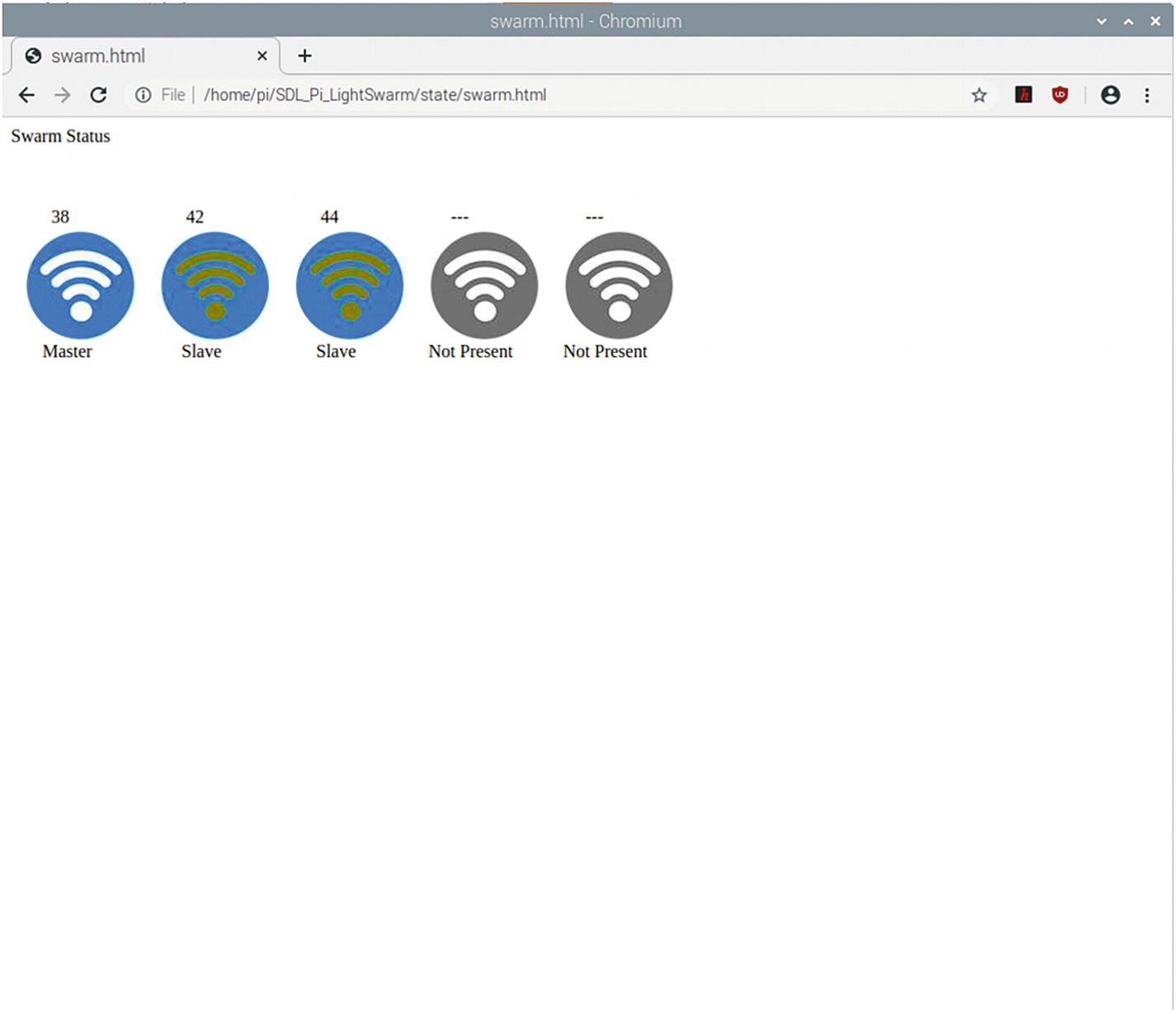
HTML Web Page Produced by Web Map Code in LightSwarm Logging Software

Listing 2-16 looks at incoming swarm IDs and builds a current table of matching IDs, removing old ones when adding new ones. The maximum number of swarm devices you can have is five, but can be easily increased.
def setAndReturnSwarmID(incomingID):
    for i in range(0,SWARMSIZE):
        if (swarmStatus[i][5] == incomingID):
            return i
        else:
            if (swarmStatus[i][5] == 0):  # not in the system, so put it in
                swarmStatus[i][5] = incomingID;
                print("incomingID %d " % incomingID)
                print("assigned #%d" % i)
                return i
    # if we get here, then we have a new swarm member.
    # Delete the oldest swarm member and add the new one in
    # (this will probably be the one that dropped out)
    oldTime = time.time();
    oldSwarmID = 0
    for i in range(0,SWARMSIZE):
        if (oldTime > swarmStatus[i][1]):
            ldTime = swarmStatus[i][1]
            oldSwarmID = i
    # remove the old one and put this one in....
    swarmStatus[oldSwarmID][5] = incomingID;
    # the rest will be filled in by Light Packet Receive
    print("oldSwarmID %i" % oldSwarmID)
    return oldSwarmID
Listing 2-16

Incoming Swarm Analysis Code

Finally, Listing 2-17 is the main code for the Python program. It is very similar in function to the setup() code for the ESP8266 in the Arduino IDE. We use this to define variables, send out one-time commands, and set up the UDP interface.
# set up sockets for UDP
s=socket(AF_INET, SOCK_DGRAM)
host = 'localhost';
s.bind(('',MYPORT))
print("--------------")
print("LightSwarm Logger")
print("Version ", VERSIONNUMBER)
print("--------------")
# first send out DEFINE_SERVER_LOGGER_PACKET to tell swarm where to send logging information
SendDEFINE_SERVER_LOGGER_PACKET(s)
time.sleep(3)
SendDEFINE_SERVER_LOGGER_PACKET(s)
# swarmStatus
swarmStatus = [[0 for x  in range(6)] for x in range(SWARMSIZE)]
# 6 items per swarm item
# 0 - NP  Not present, P = present, TO = time out
# 1 - timestamp of last LIGHT_UPDATE_PACKET received
# 2 - Master or slave status   M S
# 3 - Current Test Item - 0 - CC 1 - Lux 2 - Red 3 - Green  4 - Blue
# 4 - Current Test Direction  0 >=   1 <=
# 5 - IP Address of Swarm
for i in range(0,SWARMSIZE):
    swarmStatus[i][0] = "NP"
    swarmStatus[i][5] = 0
#300 seconds round
seconds_300_round = time.time() + 300.0
#120 seconds round
seconds_120_round = time.time() + 120.0
completeCommand()
Listing 2-17

LightSwarm Logger Startup Code

Listing 2-18 provides the main program loop. Note this is very similar to the loop() function in the ESP8266 Swarm code. In this code, we check for incoming UDP packets, process commands from LSCommand, update status information, and perform periodic commands. It is in this loop that we would be storing the Swarm status, packets, and information if we wanted to be able to analyze the swarm behavior from the archival data.
while(1) :
    # receive datclient (data, addr)
    d = s.recvfrom(1024)
    message = d[0]
    addr = d[1]
    if (len(message) == 14):
        if (message[1] == LIGHT_UPDATE_PACKET):
            incomingSwarmID = setAndReturnSwarmID((message[2]))
            swarmStatus[incomingSwarmID][0] = "P"
            swarmStatus[incomingSwarmID][1] = time.time()
            #print("in LIGHT_UPDATE_PACKET")
        if ((message[1]) == RESET_SWARM_PACKET):
            print("Swarm RESET_SWARM_PACKET Received")
            print("received from addr:",addr)
        if ((message[1]) == CHANGE_TEST_PACKET):
            print("Swarm CHANGE_TEST_PACKET Received")
            print("received from addr:",addr)
        if ((message[1]) == RESET_ME_PACKET):
            print("Swarm RESET_ME_PACKET Received")
            print("received from addr:",addr)
        if ((message[1]) == DEFINE_SERVER_LOGGER_PACKET):
            print("Swarm DEFINE_SERVER_LOGGER_PACKET Received")
            print("received from addr:",addr)
        if ((message[1]) == MASTER_CHANGE_PACKET):
            print("Swarm MASTER_CHANGE_PACKET Received")
            print("received from addr:",addr)
        #for i in range(0,14):
        #    print("ls["+str(i)+"]="+format((message[i]), "#04x"))
    else:
        if ((message[1]) == LOG_TO_SERVER_PACKET):
            print("Swarm LOG_TO_SERVER_PACKET Received")
            # process the Log Packet
            logString = parseLogPacket(message)
            buildWebMapToFile(logString, SWARMSIZE )
        else:
            print("error message length = ",len(message))
    if (time.time() >  seconds_120_round):
        # do our 2 minute round
        print(">>>>doing 120 second task")
        sendTo = random.randint(0,SWARMSIZE-1)
        SendBLINK_BRIGHT_LED(s, sendTo, 1)
        seconds_120_round = time.time() + 120.0
    if (time.time() >  seconds_300_round):
        # do our 2 minute round
        print(">>>>doing 300 second task")
        SendDEFINE_SERVER_LOGGER_PACKET(s)
        seconds_300_round = time.time() + 300.0
    processCommand(s)
Listing 2-18

Raspberry Pi Logger Main Loop

Note the last line of code, processCommands. This function is where the LSCommand.txt file is read and the commands inside the file are executed.

Results

I constructed a LightSwarm consisting of five individual swarm devices. The swarm can be seen in Figure 2-13.
../images/367492_2_En_2_Chapter/367492_2_En_2_Fig13_HTML.jpg
Figure 2-13

The LightSwarm

Finally, some results from the devices are shown in Listing 2-19. First of all is the serial debugging output from a LightSwarm device. First the device is initialized, receives an IP address from the WiFi access point (named gracie in this case), and then starts listening and sending packets. The device is swarm device #38 and receives packets from #42 and #44 but remained the master as the CC (clear color) of #28 is 9484, while the incoming packets from #42 and #44 had CC values of 253 and 626, respectively, and were both slaves.
--------------------------
LightSwarm
Version 28
--------------------------
 12/29/2020
Compiled at:12:37:09 Dec 30 2020
analogRead(A0)=133
44
Found sensor
LightSwarm Instance: 0
Connecting to gracie
...
WiFi connected
IP address:
192.168.1.38
Starting UDP
Local port: 2910
clearColor =0
MySwarmID=0
Color Temp: 3816 K - Lux: 2321 - R: 2065 G: 2514 B: 1334 C: 6445
packetbuffer[1] =0
LIGHT_UPDATE_PACKET received from LightSwarm #44
incomingID 44  assigned #1
LS Packet Recieved from #44 SwarmState:SLAVE CC:680 RC:306 GC:176 BC:209 Version=28
swarmClear[0] = 6445  swarmTimeStamp[0] = 1
#0/1/28:ME swarmClear[1] = 680  swarmTimeStamp[1] = 3074
#1/0/28:PR swarmClear[2] = 0  swarmTimeStamp[2] = -1
#2/0/0:NP swarmClear[3] = 0  swarmTimeStamp[3] = -1
#3/0/0:NP swarmClear[4] = 0  swarmTimeStamp[4] = -1
#4/0/0:NP
MasterStatus:MASTER/cc=6445/KS:(IP unset)
--------
swarmAddress[0] = 38
swarmAddress[1] = 44
swarmAddress[2] = 0
swarmAddress[3] = 0
swarmAddress[4] = 0
--------
Broadcast ToSwarm = 255 Delay = 160ms : Color Temp: 3811 K - Lux: 2322 - R: 2068 G: 2515 B: 1333 C: 6447
packetbuffer[1] =0
LIGHT_UPDATE_PACKET received from LightSwarm #42
incomingID 42  assigned #2
LS Packet Recieved from #42 SwarmState:SLAVE CC:593 RC:230 GC:180 BC:193 Version=28
swarmClear[0] = 6447  swarmTimeStamp[0] = 1
#0/1/28:ME swarmClear[1] = 680  swarmTimeStamp[1] = 3074
#1/0/28:PR swarmClear[2] = 593  swarmTimeStamp[2] = 4284
#2/0/28:PR swarmClear[3] = 0  swarmTimeStamp[3] = -1
#3/0/0:NP swarmClear[4] = 0  swarmTimeStamp[4] = -1
#4/0/0:NP
MasterStatus:MASTER/cc=6447/KS:(IP unset)
--------
swarmAddress[0] = 38
swarmAddress[1] = 44
swarmAddress[2] = 42
swarmAddress[3] = 0
swarmAddress[4] = 0
--------
Broadcast ToSwarm = 255 Delay = 216ms : Color Temp: 3812 K - Lux: 2323 - R: 2070 G: 2517 B: 1335 C: 6455
packetbuffer[1] =0
LIGHT_UPDATE_PACKET received from LightSwarm #42
LS Packet Recieved from #42 SwarmState:SLAVE CC:592 RC:229 GC:179 BC:193 Version=28
swarmClear[0] = 6455  swarmTimeStamp[0] = 1
Listing 2-19

Results from LightSwarm IoT Device Run on ESP8266

Listing 2-20 is the output from the Raspberry Pi LightSwarm logging software. The first thing the logging software does is send out a “DEFINE_SERVER_LOGGING_PACKET” to tell the swarm devices the IP address (192.168.1.40) of the server so the swarm master can send logging packets directly to the Raspberry Pi, rather than use the already crowded UDP broadcast ports. Finally, we see a packet coming in from SwarmID #42. Number 42 picked up the server address, and since it was the master of the swarm, it started sending in log packets to the Raspberry Pi. Note from the log results, it looks like #42 has friends nearby (#44 and #38) and is part of a swarm of at least three units.
--------------
LightSwarm Logger
Version  7
--------------
DEFINE_SERVER_LOGGER_PACKET Sent
lo: 127.0.0.1
eth0: No IP addr
wlan0: 192.168.1.40
['192.168.1.40']
['192', '168', '1', '40']
DEFINE_SERVER_LOGGER_PACKET Sent
lo: 127.0.0.1
eth0: No IP addr
wlan0: 192.168.1.40
['192.168.1.40']
['192', '168', '1', '40']
Swarm DEFINE_SERVER_LOGGER_PACKET Received
received from addr: ('192.168.1.40', 2910)
incomingID 42
assigned #0
incomingID 44
assigned #1
Swarm LOG_TO_SERVER_PACKET Received
incomingID 38
assigned #2
Log From SwarmID: 38
Swarm Software Version: 28
StringLength: 87
swarmElement= [' 0', '1', '28', '9493', 'PR', '38 ']
swarmElement= [' 1', '0', '28', '591', 'PR', '42 ']
swarmElement= [' 2', '0', '28', '679', 'PR', '44 ']
swarmElement= [' 3', '0', '0', '0', 'NP', '0 ']
swarmElement= [' 4', '0', '0', '0', 'NP', '0 ']
Swarm LOG_TO_SERVER_PACKET Received
Log From SwarmID: 38
Swarm Software Version: 28
StringLength: 87
swarmElement= [' 0', '1', '28', '9490', 'PR', '38 ']
swarmElement= [' 1', '0', '28', '591', 'PR', '42 ']
swarmElement= [' 2', '0', '28', '678', 'PR', '44 ']
swarmElement= [' 3', '0', '0', '0', 'NP', '0 ']
swarmElement= [' 4', '0', '0', '0', 'NP', '0 ']
Swarm DEFINE_SERVER_LOGGER_PACKET Received
received from addr: ('192.168.1.40', 2910)
Swarm LOG_TO_SERVER_PACKET Received
Log From SwarmID: 38
Swarm Software Version: 28
StringLength: 87
swarmElement= [' 0', '1', '28', '9490', 'PR', '38 ']
swarmElement= [' 1', '0', '28', '592', 'PR', '42 ']
swarmElement= [' 2', '0', '28', '678', 'PR', '44 ']
swarmElement= [' 3', '0', '0', '0', 'NP', '0 ']
swarmElement= [' 4', '0', '0', '0', 'NP', '0 ']
Swarm LOG_TO_SERVER_PACKET Received
Log From SwarmID: 38
Swarm Software Version: 28
StringLength: 87
swarmElement= [' 0', '1', '28', '9483', 'PR', '38 ']
swarmElement= [' 1', '0', '28', '592', 'PR', '42 ']
swarmElement= [' 2', '0', '28', '678', 'PR', '44 ']
swarmElement= [' 3', '0', '0', '0', 'NP', '0 ']
swarmElement= [' 4', '0', '0', '0', 'NP', '0 ']
Listing 2-20

Output from Raspberry Pi LightSwarm Logger

What Else Can You Do with This Architecture?

The LightSwarm architecture is flexible. You can change the sensor, add more sensors, and put in more sophisticated algorithms for swarm behavior. In Chapter 5, we extend this architecture to more complex swarm behavior, actually changing some of the physical environment of the swarm devices.

Conclusion

A good part of the IoT will be the gathering of simple, small amounts of data, some analysis on the data, and the communication of that data to servers for action and further analysis on the Internet. The projects in Chapters 3 and 4 are of more complex IoT devices gathering lots of data, processing it, acting on the data, and communicating summaries to the Internet. The LightSwarm is different in that each Swarm element is simple and cooperates without a central controller to determine which element has the brightest light and then will act on that information (turning the red LED on).

Swarms of IoT devices can be made inexpensively, can exhibit unexpected complex behavior, and can be devilishly difficult to debug. If you are trying to debug such a system, log everything during development!!!

..................Content has been hidden....................

You can't read the all page of ebook, please click here login for view all page.
Reset
18.224.38.3