8
Project Prototype to Product – How?
We are almost at the finish line. This book has covered all the essentials required to get yourself familiar with numerous concepts related to Raspberry Pi and MQTT. But this is just the beginning! Now, the most important question arises: What Next?
This chapter provides the answer to this question. We will be covering a lot of important things that will assist you in choosing your future path.
In this chapter, we will cover the following topics:
- Innovative project ideas
- IoT services provided by enterprise cloud platforms
- How to scale your projects using the current hardware
So, let’s get started!
Innovative project ideas
“Building projects is the best way to learn a technology, period.”
This is the motto I believe in. Learning a technology is not just about theory. You can read more than 100 books on a single piece of technology but to master it, you have to have hands-on experience in working with that technology. This helps you not only understand the nitty gritty details but also learn new things that you have to pick up while building a project:
Figure 8.1 – It all starts with an idea!
The projects chosen in this book were handpicked by me as I built them when I was first getting familiar with Raspberry Pi. We will cover two very popular project ideas that you can build to further expand your knowledge of Pi and the MQTT communication protocol.
Please note that this section only provides an overview of these ideas; you will have to research yourself and build them, which is how you will learn and master various technological skills.
Idea 1 – Home automation system
Smart homes are quickly gaining popularity, all thanks to the cheaper and more powerful hardware available on the market currently. This is not a new concept and has been implemented by thousands of DIY enthusiasts, including myself:
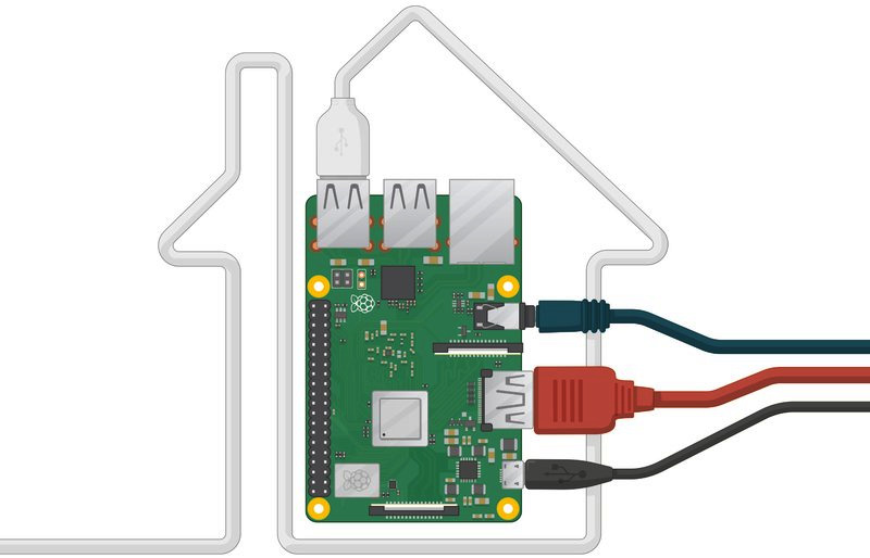
Figure 8.2 – Home automation in a nutshell
The preceding figure signifies how easy home automation is to implement. A single Raspberry Pi can act as a hub for your entire home automation system!
The main advantage of this idea is that you can implement it at any scale, from a single appliance to a whole house being controlled through a single hub. Let’s discuss how you can use your existing skillset to create this project. First, by now, it should be clear how the hardware components will be used. You will use the following:
- A Raspberry Pi, which will act as the central hub for your home automation ecosystem. It will be used to control all the client or end node devices.
- The ESP32 and ESP8266-based home automation projects will be used as the client. You can use the Major Project 2 that you built directly for this. You will need multiple projects to create this at a larger scale. For instance, one such project will be required for each room of your apartment or house.
Idea 2 – air quality monitoring system
Air is essential to sustain life on our planet. As we all must have studied in school, air is 78% nitrogen, 21% oxygen, and 1% argon; the rest of the gases are very minute in volume. Nonetheless, several gases are categorized as polluters, with carbon dioxide being the main culprit. Apart from this, there are other minute solid particles that greatly affect human health, known as particulate matter. They are categorized based on particulate size (in microns), and the two major types are PM2.5 and PM10. Three main components can be used to monitor these with a conventional air quality monitoring system.
You can simply connect one of the commercially available sensors to your Raspberry Pi and write some simple Python code to start monitoring these parameters. You can choose any sensor of your choice for this purpose. Some options are as follows:
- Honeywell HPM Particle sensor: This provides laser-based light scattering particle sensing, including PM1.0, PM2.5, PM4.0, and PM10. It responds in less than 6 seconds, has UART, and has standard and compact versions. These are just some of the characteristics of this sensor:
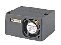
Figure 8.3 – Honeywell HPM Particle Sensor
- SDS011 sensor: This is a recently developed air quality sensor created by a company called Nova Fitness. You can monitor PM2.5 and PM10 readings using this sensor:
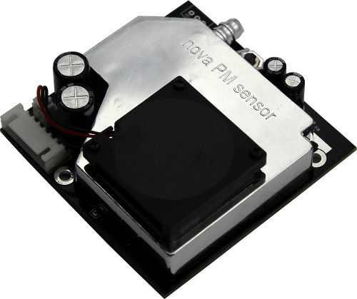
Figure 8.4 – SDS011 sensor
You will also require a UART interface if you want to connect any of these sensors to the Pi. However, most sensors come with a USB to Serial connector, as shown here:

Figure 8.5 – USB to Serial connector for sensors
Regarding the software, you will need to code in Python to read the values from the sensor through UART. What you do with these values is up to you. You can create a Node-RED dashboard, like the one we created for the weather station, or you can use external data visualization or storage tools such as Adafruit IO, ThingSpeak, and so on. The following is an example dashboard for this project:
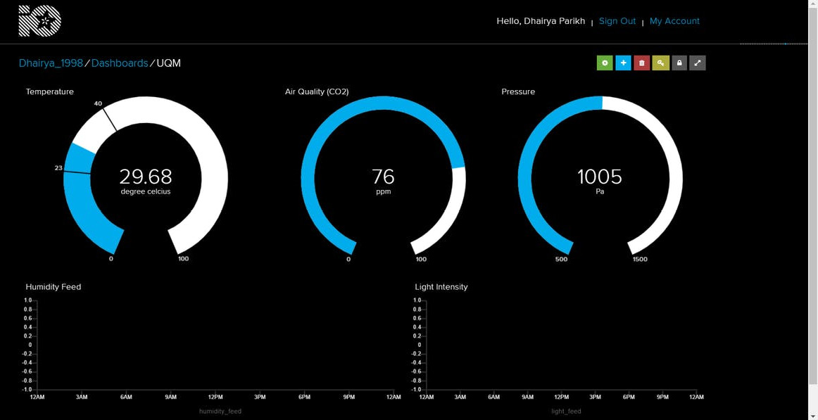
Figure 8.6 – Example quality monitoring dashboard (Adafruit IO)
In this section, we discussed two very popular ideas that you can implement using the skills you’ve learned throughout this book. Now, we will explore some IoT services offered by enterprise cloud platforms such as Amazon Web Services (AWS) and Google Cloud Platform (GCP) and create a simple project using one such service – you learn best by doing!
IoT services provided by enterprise cloud platforms
Modern cloud platforms such as AWS, GCP, and Azure provide a fully managed IoT system architecture that can help you do the following:
- Data collection and analysis
- Remote access and deployments
- IoT data security
- Third-party application integrations
The main advantage of using such a platform is that the hardware is completely managed by the cloud service provider, along with data security and access control management. This creates a very powerful and useful platform for a user managing numerous IoT devices on a single platform.
The whole system architecture is broken into four parts:
- Hardware Layer: All the IoT sensors and devices fall under this layer. Their primary task is data collection and sharing.
- Network Layer: The data that’s collected by the sensors must reach the IoT cloud platform in some way and that is through this layer. This can be a direct transfer – that is, through Wi-Fi or Ethernet to the platform – or an indirect transfer, through an IoT gateway. Here, the hardware shares its data over a local network to the gateway (which can be a Raspberry Pi as well!) through BLE, WiFi, Zigbee, and so on, and then the data is shared to the IoT platform over the internet.
- Middleware Layer: The cloud platform’s IoT services fall in this layer – that is, a fully managed IoT platform with numerous features and advantages over the conventional platforms.
- Application Layer: This is the final layer where all the applications fall and is what the end users use. They can be a customer, a data analyst – anyone. The application could be a mobile application, web dashboard, and so on.
Now, let’s discuss two such platforms in brief, after which we will create a simple project, wherein we will demonstrate how to connect Node MCU to AWS IoT Core.
IoT cloud platforms
With the global IoT market rapidly progressing, an enterprise solution to handle all the IoT-related applications is essential. This is where the IoT cloud platforms come in. These platforms make the task of hosting an IoT service a lot easier as it only manages the hardware, software (in some use cases), and maintenance. All we need to do is host our service and write the product-specific code.
We will discuss two major IoT platforms in brief in this section: AWS and GCP.
Amazon Web Services
Amazon provides a range of services when it comes to IoT. The main advantage of these services is that they are completely managed and scalable and support almost an unlimited number of devices and message transfers. There are several use cases for the platform: industrial (IIoT), consumer and commercial markets, and more. Some popular IoT services that AWS provides are as follows:
- AWS IoT Core: This allows seamless and secure connections between devices over a fully managed architecture
- AWS IoT Device Defender: Security and auditing for your IoT devices
- AWS IoT Device Management: Register, monitor, and manage your IoT devices
- FreeRTOS: A lightweight operating system for microcontrollers for low-power edge devices
- AWS IoT Greengrass: For managing intelligent IoT devices on the edge
Google Cloud Platform
GCP allows the IoT Core service to link your IoT devices to the cloud. It is a highly scalable and fully managed service offered by GCP, which maintains a unique logical configuration for each device.
One of the defining features of this service is automatic load balancing, which means the architecture automatically scales up when the number of devices or the data traffic increases.
There are two major components of the IoT Core service:
- Device Manager: This manages all the connected IoT devices, including authentication, registration, and configuration management. It even helps you control your devices remotely from the cloud.
- Protocol Bridge: This component’s main task is to provide a way to connect your IoT device to Google Cloud through various wireless communication protocols (for example, HTTP and MQTT).
Now that we’ve covered AWS and GCP, let’s implement what we’ve discussed practically by connecting a Node MCU device to AWS IoT Core and sending BME280 sensor data to the cloud.
Project – getting started with AWS IoT Core
In this section, we will connect our Node MCU to a Wi-Fi network and, through that, connect it to AWS IoT Core. We will demonstrate the publish and subscribe capabilities by sending BME280 Sensor data to the cloud and sending a simple Hello World message from the cloud to the Node MCU development board.
Project hardware setup
To get started, we need to connect the BME280 sensor to the Node MCU. The following is a circuit diagram for the same:
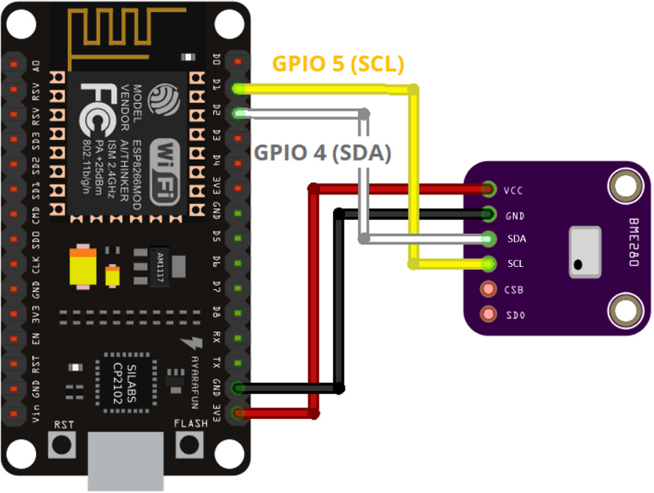
Figure 8.7 – NodeMCU BME280 schematic diagram
The preceding diagram shows that you need to connect the BME280 sensor to our NodeMCU development board. Now, let’s set up the AWS IoT Core environment.
AWS IoT Core setup
First, we must set up AWS IoT Core. To do so, you must go to https://aws.amazon.com/:
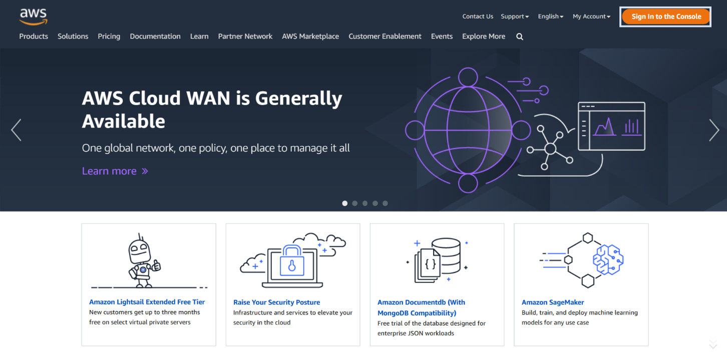
Figure 8.8 – AWS home page (click on the Sign in to the Console button)
Next, you must click on the Sign in to the Console button, which will redirect you to a new sign-in page. If you already have an active AWS account, just sign in using those user credentials; otherwise, just go to https://portal.aws.amazon.com/billing/signup, which will let you create a new account under the free tier.
Please note that you will need to enter your credit card details for the sign-up process, just for verification purposes. You will not be charged for anything until you use the services as you can stay within the free tier limits. Once you have signed in to your account, go to the AWS IoT Core service home page. You can do that either by searching for it via the Console search bar, going to the Service tab, or by going to https://aws.amazon.com/iot-core/.
This will open the AWS IoT dashboard, as shown in the following screenshot:
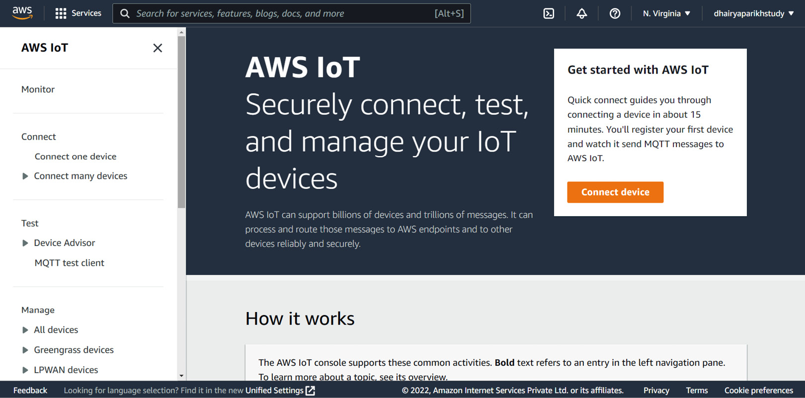
Figure 8.9 – The AWS IoT Core dashboard
Next, we have to connect our device to AWS IoT Core. For this, we need something called a thing, which is the representation of your physical device in the cloud. Just click on All Devices from the right pane and then click on Things from the dashboard home page. This will open a new web page that will take you through the thing registration process. Just click the Create things button:
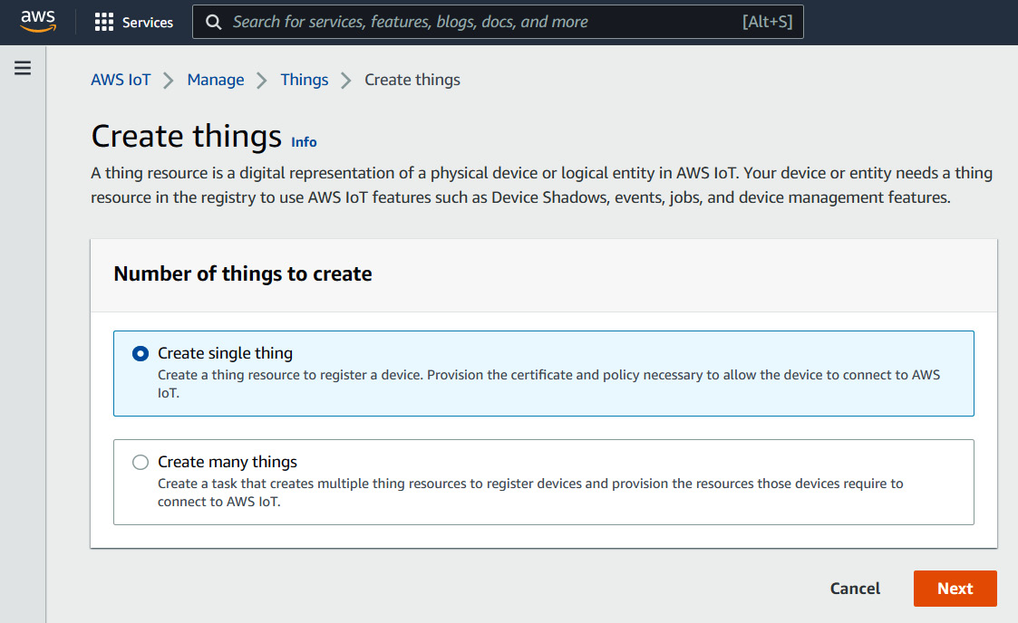
Figure 8.10 – Creating a new thing (AWS IoT)
We just need to create a single thing (for our Node MCU), so press Next. You will have to go through three steps to create a thing on AWS, as shown here:
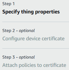
Figure 8.11 – Steps to create a thing on AWS IoT Core
In Step 1, all we need to do for now is give our thing a name. I will be naming it NodeMCU for this tutorial; you can name it whatever you like. There is no need to change any additional settings. Just press Next after you have given your thing an appropriate name:
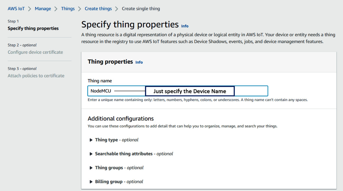
Figure 8.12 – Creating a new thing (Step 1)
The next step is to configure a certificate file (also known as a CSR) for your thing. This file is used for authentication purposes and is very important for maintaining security standards. We can either create a new certificate file (which we are going to do now) or upload an existing CSR file and skip this step.
We will just let AWS auto-generate the certificate for us (which is selected by default) and press Next:

Figure 8.13 – Step 2 – Configure device certificate
The next step is to attach policies to this certificate, which means configuring what the device should be able to do (connect, subscribe, publish, and so on). For this tutorial, we need all three functionalities, so we will be creating our policy accordingly. Just click the Create policy button:
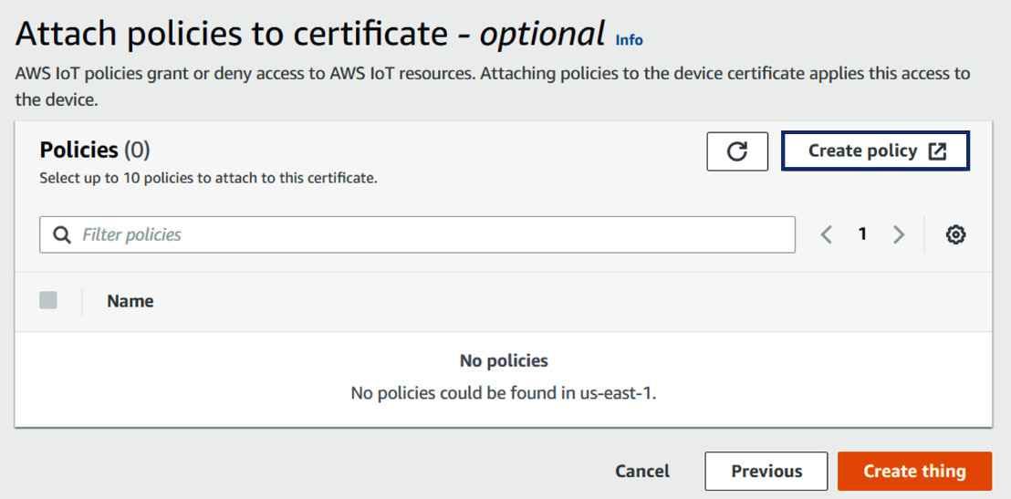
Figure 8.14 – Creating a new policy for our certificate
To create such a policy, we will need to add four policy actions. First, just give your policy a unique name (I have named mine NodeMCU_Policy), and then add the following actions:
- Iot:Connect
- Iot:Publish
- Iot:Subscribe
- Iot:Receive
Note that we need to allow all these policies. Moreover, we need the resource ARN for our thing for each policy. Getting this is a bit tricky, so the easy way is to choose a connect policy from the Policy examples tab; this will give you the resource ARN. Which looks something like this:
arn:aws:iot:us-east-1:316634146583
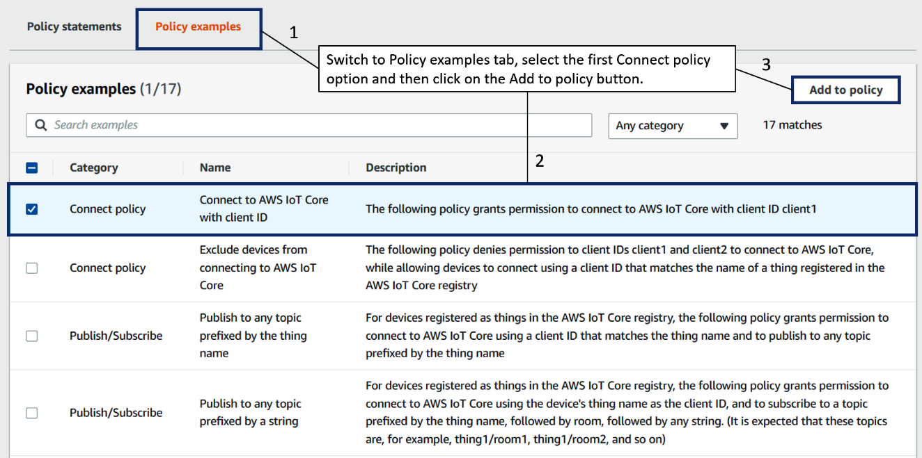
Figure 8.15 – Adding an example policy to get the resource ARN
Now, we need to fill in the following in the Policy resource section for each action:
- Connect: *
- Publish: *
- Subscribe: *
- Receive: *
Please note that if we want to add the Subscribe action, we need both the Receive and Subscribe actions. The first will allow the thing to receive messages, while the second will let you subscribe to any particular MQTT topic. * is a wildcard, which implies that any AWS resource that applies this policy will be able to access all the mentioned actions. Once all the actions have been set, the policy document will look something like this:
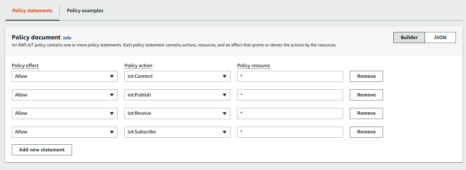
Figure 8.16 – Policy document configuration
After the configuration is complete, just click on the Create policy button. Your policy should appear in the AWS IoT Policies section, as well as the Add policy to certificate section (Step 2, remember?) for which we created this.
Just select the policy to attach it to the certificate and then press the Create thing button.
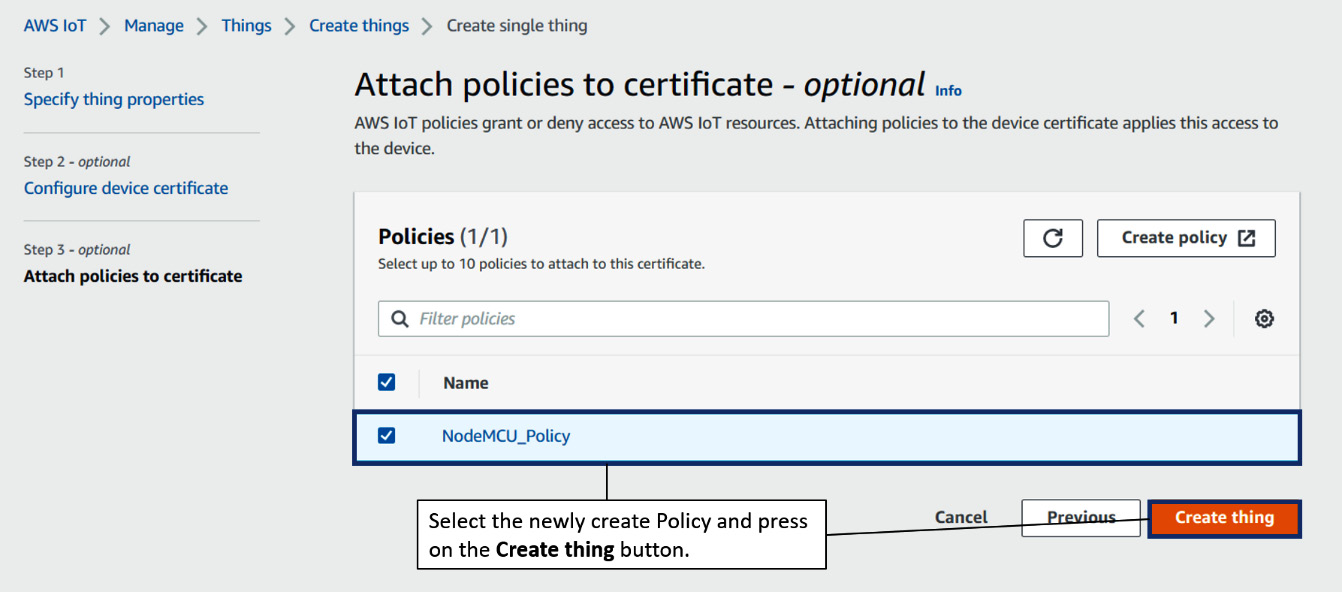
Figure 8.17 – Attaching our policy to the certificate and creating our thing
Now, a new window will pop up that lists all the key and certificate files that have been created. Here, we need to download four files:
- Certificate file
- Public key
- Private key
- The root CA 1 RSA 2,048-bit key
Please rename the files according to the names provided here to avoid confusion in the future. The following screenshot shows which files need to be downloaded for this tutorial:

Figure 8.18 – The Download certificates and keys view
Once all the necessary files have been downloaded, just press the Done button. This concludes all the setup required from AWS IoT Core. Now comes the interesting part! We will write the code that will let the Node MCU board establish a connection with AWS IoT Core and allow us to publish and subscribe to the topics we mentioned during the setup.
For better reference, here are the publish and subscribe topic names we will be using for this project:
- Publish Topic: ESP8266/publish
- Subscribe Topic: ESP8266/subscribe
Let’s start by explaining the code for this project.
Code explanation
The NodeMCU code we will be writing for this project will do the following:
- Connect to a Wi-Fi network.
- Establish a connection with AWS IoT Core.
- Get the sensor data, create a JSON file, and publish it on the Publish topic.
- Subscribe and print any messages that have been published on the Subscribe topic.
First, we will do something different in this project, which is a better practice than what we have done so far. We will store all the sensitive data information such as the certificates, private key, Wi-Fi credentials, and the AWS endpoint address in a separate secrets.h file for more secure and flexible usage of these parameters in our main code.
To do this, just create a new tab after creating a new Arduino file by going to the downward arrow icon at the top-right of the Arduino IDE window and expanding the menu to find and click the Create New Tab option. Save the file with the name secrets.h.
Now, let’s look at a step-by-step explanation of the code, as we have done in all the previous projects. We have two files, so we will divide this section into two parts as well. Let’s start with the secrets.h file:
#include <pgmspace.h>
#define SECRET
const char WIFI_SSID[] = "…";               //Wifi SSID Name
const char WIFI_PASSWORD[] = "….";           //Wifi Password
#define THINGNAME "…." // Name of your thing in AWS
int8_t TIME_ZONE = +5.5; //IST(India): +5.5 UTC (Time Zone parameter)
const char MQTT_HOST[] = "xxxxxxxxxxxxxx-ats.iot.us-east-1.amazonaws.com"; // Get this from the AWS IoT Core Settings
static const char cacert[] PROGMEM = R"EOF(
-----BEGIN CERTIFICATE-----
[…………]
-----END CERTIFICATE-----
)EOF";
// Copy contents from XXXXXXXX-certificate.pem.crt here ▼
static const char client_cert[] PROGMEM = R"KEY(
-----BEGIN CERTIFICATE-----
[…………]
-----END CERTIFICATE-----
)KEY";
// Copy contents from  XXXXXXXX-private.pem.key here ▼
static const char privkey[] PROGMEM = R"KEY(
-----BEGIN RSA PRIVATE KEY-----
[…………]
-----END RSA PRIVATE KEY-----
)KEY";
This file is used to store all the sensitive and reusable parameters of the main code. Let’s look at these parameters:
- First are the Wi-Fi credentials, which must be specified.
- Next, you need to store the name of the thing you gave on AWS IoT as this will be used as the client’s name to establish a connection.
- The TIME_ZONE parameter (the difference between your time zone and UTC in hours) will be used to fetch the latest UTC (covered later in the code).
- MQTT_HOST will contain the AWS endpoint, which will be used as the MQTT host. It can be fetched by going to the settings of AWS IoT Core. The following screenshot shows where you can find it:
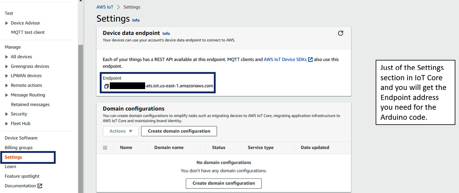
Figure 8.19 – Getting the AWS endpoint for the project
- Finally, we need to store the certificate, private key, and the Amazon Root CA1 certificate we downloaded from AWS. To get the text data of these certificates, just open them in Notepad and copy and paste their contents into this file accordingly. You will find comments to help you out with this.
Next, we will write the main code for this project, in which we will include this secrets.h file so that we have access to all the variables and constants we defined in it.
Chapter_8_Project_Code.ino
Since this code is quite large, we have broken it into short snippets for easier understanding and explanation. First, we must import the necessary libraries:
#include <ESP8266WiFi.h>
#include <WiFiClientSecure.h>
#include <PubSubClient.h>
#include <ArduinoJson.h>
#include <time.h>
#include <Wire.h>
#include <Adafruit_BMP280.h>
#include "secrets.h"
As you can see, we will be using some new libraries we haven’t covered:
- The WiFiClientSecure.h file is a subpart of the ESP8266WiFi library and will be used to connect to AWS IoT Core using the certificate and private key we downloaded. To learn more about this, go to https://arduino-esp8266.readthedocs.io/en/latest/esp8266wifi/bearssl-client-secure-class.html.
- The ArduinoJSON library will be used to format the sensor data in JSON format before it’s published on our topic. This is a good practice and can be implemented in the projects we covered previously in this book as well. Please note that you will have to download ArduinoJSON version 6.0 or higher for this project. Please visit the library documentation to learn more about this library: https://arduinojson.org/v6/doc/.
- The time.h file is used to get access to certain functions to set the time as per your time zone for the NodeMCU board. This is important as the current time is required for certification verification of AWS IoT.
Now, let’s look at the variable, object, and constant declarations:
// BMP 280 Sensor value variables
float temperature_C ;
float pressure ;
float altitude ;
// Variables to implement publish every 5 second logic
unsigned long lastMillis = 0;
unsigned long previousMillis = 0;
const long interval = 5000;
// variables to store the latest time fetched by the NTP Client.
time_t now;
time_t nowish = 1510592825;
// AWS Publish and subscribe topic mentioned in the AWS policy you created
#define AWS_IOT_PUBLISH_TOPIC   "ESP8266/publish"
#define AWS_IOT_SUBSCRIBE_TOPIC "ESP8266/subscribe"
// WiFi SSL to add the certificates and key we retrieved from AWS
WiFiClientSecure net;
BearSSL::X509List cert(cacert);
BearSSL::X509List client_crt(client_cert);
BearSSL::PrivateKey key(privkey);
// Objects for pubsub and BMP sensor
PubSubClient client(net);
Adafruit_BMP280 bmp;
The next step is to initialize all the necessary variables, constants, and objects that we will be using in this code. Certain variables have been used without any initializations (their style has been changed to bold). This is because they have been defined in the secrets.h file, which we will define at the end.
Now, let’s look at the NTPConnect function:
void NTPConnect(void)
{
  Serial.print("Setting time using SNTP");
  configTime(TIME_ZONE * 3600, 0 * 3600, "pool.ntp.org", "time.nist.gov");
  now = time(nullptr);
  while (now < nowish)
  {
    delay(500);
    Serial.print(".");
    now = time(nullptr);
  }
  Serial.println("done!");
  struct tm timeinfo;
  gmtime_r(&now, &timeinfo);
  Serial.print("Current time: ");
  Serial.print(asctime(&timeinfo));
}
This function is used to fetch the latest time. This is required for proper authentication, as discussed previously. Please note that the only thing you need to keep in mind here is the TIME_ZONE variable, which will also be defined in the secrets.h file. This is the number by which the time in your region is behind or ahead of the UTC (as we need UTC for authentication).
Now, let’s look at the MQTT callback function:
void messageReceived(char *topic, byte *payload, unsigned int length)
{
  Serial.print("Received [");
  Serial.print(topic);
  Serial.print("]: ");
  for (int i = 0; i < length; i++)
  {
    Serial.print((char)payload[i]);
  }
  Serial.println();
}
This is the standard MQTT callback function we have been using throughout this book. It prints the incoming messages on the subscribed topics on the Serial monitor.
Now, let’s look at the Setup_WiFi() function:
void Setup_WiFi()
{
  delay(10);
  // We start by connecting to a WiFi network
  Serial.println(String("Attempting to connect to SSID: ") + String(WIFI_SSID));
  WiFi.mode(WIFI_STA);
  WiFi.begin(WIFI_SSID, WIFI_PASSWORD);
  while (WiFi.status() != WL_CONNECTED)
  {
    delay(500);
    Serial.print(".");
  }
  randomSeed(micros());
  Serial.println("");
  Serial.println("WiFi connected!");
  Serial.println("IP address: ");
  Serial.println(WiFi.localIP());
}
The main purpose of this function is to establish a network connection over Wi-Fi using the credentials you will specify in the secrets.h file (WIFI_SSID and WIFI_PASSWORD).
Now, let’s look at the connectAWS() function:
void connectAWS()
{
  delay(3000);
  Setup_WiFi();
  NTPConnect();
  net.setTrustAnchors(&cert);
  net.setClientRSACert(&client_crt, &key);
  client.setServer(MQTT_HOST, 8883);
  client.setCallback(messageReceived);
  Serial.println("Connecting to AWS IOT");
  while (!client.connect(THINGNAME)) {
    Serial.print(".");
    delay(1000);
  }
  if (!client.connected()) {
    Serial.println("AWS IoT Timeout!");
    return;
  }
  // Subscribe to a topic
  client.subscribe(AWS_IOT_SUBSCRIBE_TOPIC);
  Serial.println("AWS IoT Connected!");
}
This function does the following:
- Connects to Wi-Fi by calling the setup_wifi function.
- Gets the latest time by calling the NTPConnect function.
- Establishes a connection with the AWS MQTT endpoint (this will be fetched from the AWS IoT Core settings) and initializes the callback function.
- Tries to establish a connection with the thing we created. If a connection can be established, it subscribes to the topic we have specified in our AWS IoT policy (the topic name is already defined).
Now, let’s look at the publishMessage() function:
void publishMessage()
{
  StaticJsonDocument<200> doc;
  doc["time"] = millis();
  doc["temperature"] = temperature_C;
  doc["pressure"] = pressure;
  doc["altitude"] = altitude;
  char jsonBuffer[512];
  serializeJson(doc, jsonBuffer); // print to client
  client.publish(AWS_IOT_PUBLISH_TOPIC, jsonBuffer);
}
This function’s primary task is to store the latest BMP sensor values in a JSON document, convert it into a char array, and then publish this data on the AWS Publish topic we defined in the code.
Now, let’s look at the setup() function:
void setup()
{
  Serial.begin(115200);
  if (!bmp.begin(0x76)) {
    Serial.println(F("Could not find a valid BMP280 sensor, check wiring or "
                      "try a different address!"));
    while (1) delay(10);
  }
  // Default settings from datasheet
  bmp.setSampling(Adafruit_BMP280::MODE_NORMAL,
                  Adafruit_BMP280::SAMPLING_X2,
                  Adafruit_BMP280::SAMPLING_X16,
                  Adafruit_BMP280::FILTER_X16,
                  Adafruit_BMP280::STANDBY_MS_500);
  connectAWS();
}- Initialize or open a Serial connection with a baud rate of 115200.
- Check if the BMP sensor is connected, and if it is, specify the default setting parameters for it.
- Call the connectAWS function, which connects to Wi-Fi, sets up the latest time, and connects to AWS IoT Core.
Now, let’s look at the loop() function:
void loop()
{
  temperature_C = bmp.readTemperature();
  pressure = bmp.readPressure();
  altitude = bmp.readAltitude(1013.25);
  Serial.print(F("Temperature : "));
  Serial.print(temperature_C);
  Serial.print(F("%  Pressure : "));
  Serial.print(pressure);
  Serial.print(F("   Altitude : "));
  Serial.println(altitude);
  delay(2000);
  now = time(nullptr);
  if (!client.connected())
  {
    connectAWS();
  }
  else
  {
    client.loop();
    if (millis() - lastMillis > 5000)
    {
      lastMillis = millis();
      publishMessage();
    }
  }
}
This is the final loop() function in which we will fetch the latest BMP sensor values and print them on the Serial monitor and set up the latest time. After that, we will check whether a connection with AWS IoT Core has been established and, if it has, publish the sensor values on the AWS Publish topic (ESP8266/publish in this case) every 5 seconds.
With that, we’ve explained the code. Now, we will see the project in action, for which we will be using the MQTT test client provided by AWS IoT.
Project demonstration
Now that everything has been set up, we are ready to test the project! Once you have connected the BMP280 sensor to the NodeMCU board, just upload the code to the board. If everything has been done according to this tutorial, you will be able to upload the code onto the board successfully. This completes the setup on the hardware end.
Next, you will have to open the AWS IoT Core dashboard from the left pane and select the MQTT test client option, which you can find under the Test section. This will open a new page that will look something like this:

Figure 8.20 – The MQTT test client page
This is a web-hosted MQTT client that has already been connected to your AWS endpoint. You can publish and subscribe to different topics through this tool. Now, let’s check whether we can receive the BMP280 sensor values from our NodeMCU. For that, just add the ESP8266/publish text under Topic filter in the Subscribe to a topic section and click the Subscribe button.
Now, connect the NodeMCU to a power source and wait for a few seconds (setting up the latest time takes some time). You should be able to see the sensor values on the screen every 5 seconds:

Figure 8.21 – NodeMCU sensor values every 5 seconds
Great! Now, let’s test whether our NodeMCU board can print messages that have been published on the ESP8266/subscribe topic (specified in the code). For this, just open the Publish to a topic section on the MQTT test client tool and type the aforementioned topic name in the Topic name textbox. Keep the message payload as is. Before publishing the message, open the Serial monitor for your NodeMCU board as you will be able to see the message there.
Once you have it open, click the Publish button. You should be able to see the message there, as shown here:
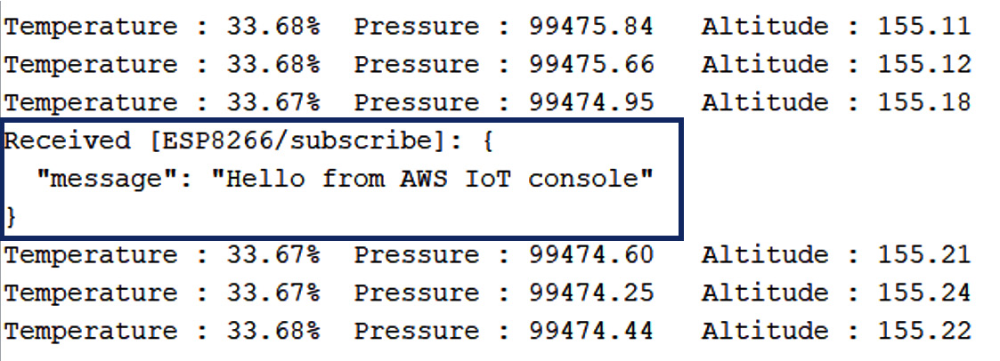
Figure 8.22 – Sample message published through the MQTT test client on AWS
This marks the end of this section. The possibilities with this are endless as we can pass this data through any of the available AWS services to create dashboards, run inference by passing them through trained ML models, and even use this data to train a machine learning model. We can even create automations using AWS Lambda – this is just the tip of the iceberg. This is a step you will take only after you have scaled your projects to a certain level as these enterprise solutions are pretty expensive and the complexity of the solutions also increases after adding different AWS services into the mix. Now, let’s learn how to scale them immediately and on a much smaller scale.
How to scale your projects using the current hardware
We discussed a lot of options for scaling our current setup, starting with using a cloud-hosted MQTT broker, in Chapter 7, Taking Your MQTT Broker Global. In the previous section, we discussed how we can use enterprise IoT platforms for this. But the main drawback of such products is that they are quite expensive and although they do provide customizations, there are always some drawbacks you may face while working on a particular use case.
For this reason, I have added this section as well. This will give you a gentle introduction to all the tools you will need to build an actual product using the existing tools that you have. For maximum customization, you always need to have your own software base, which you will have to develop from scratch. There are several approaches that you can take to achieve this, and, in this section, we will cover a few of them.
So, without further ado, let’s get started.
Home Assistant
Node-RED, though easy to use, has its limitations as it was created for educational purposes. Moreover, there are far more capable software packages built specifically for home automation such as Home Assistant, openHAB, and IFTTT.
In this section, we will discuss one of the most popular and obvious choices – Home Assistant:
This system provides several advantages over the existing Node-RED system that we use:
- Its major advantage is the number of supported devices, specifically commercial home automation devices such as Philips Hue smart lights, Google’s Nest thermostat, and more. All such devices can be configured with our current setup without any hassle. All such connections are referred to as Configurations in Home Assistant. At the time of writing, there are 1,800+ such configurations available and they keep on adding more.
- We can even add different wireless connectivity modes to our system just by connecting an external board to our Raspberry Pi. For instance, you can add Zigbee support to the system just by adding a Zigbee support board to your Raspberry Pi.
- One of the most impactful advantages of using Home Assistant is the developer community. It has a very active and helpful community that can support you every step of the way.
Now, to get started with Home Assistant on the Raspberry Pi, you just need to create an OS image to specifically run the Home Assistant application. To do this, you must follow some steps that are similar to those you followed to set up your SD card in Chapter 1, Introduction to Raspberry Pi and MQTT (Setting up the SD card) with a small change:
- When you open the Raspberry Pi Imager and click on the Choose OS button, you have to select the Home Assistant option instead of the latest Raspberry Pi OS build. The following screenshot shows how to select it:
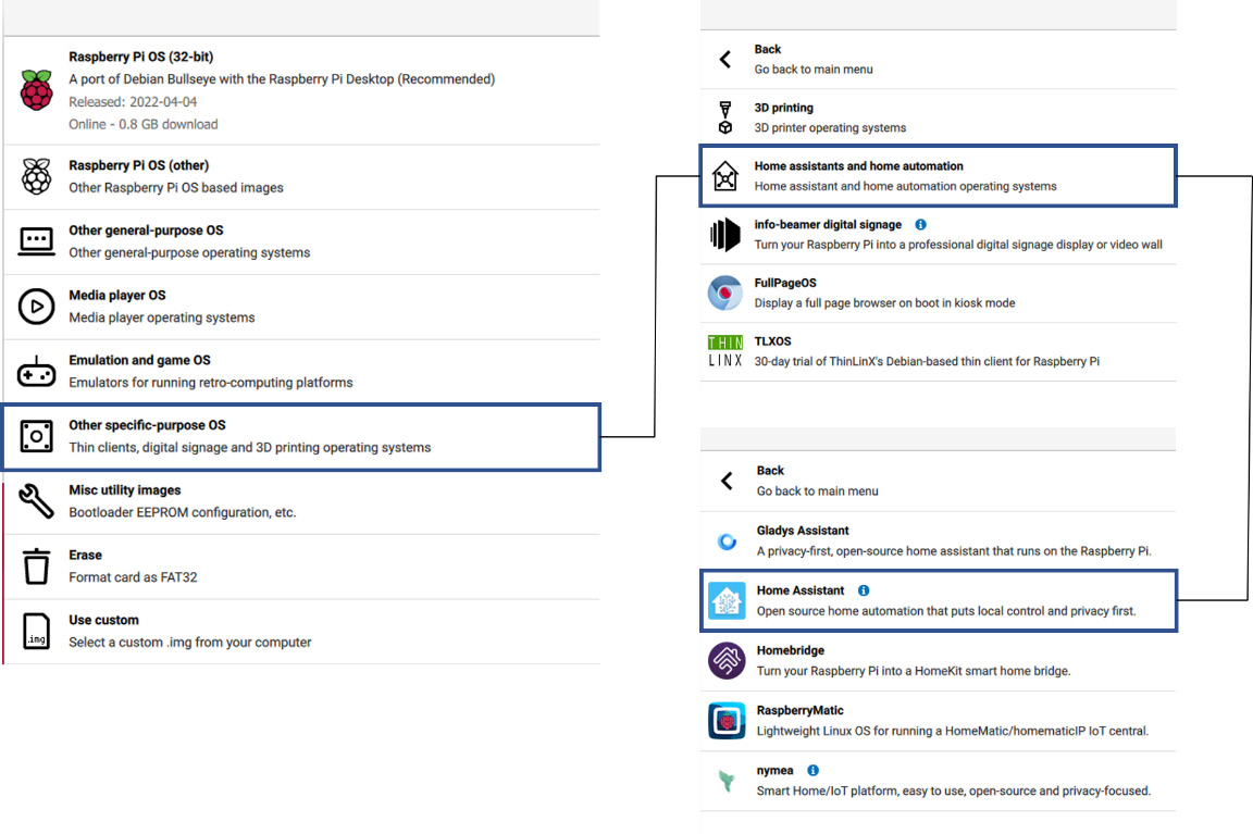
Figure 8.23 – Installing and flashing the Home Assistant OS on the Raspberry Pi
- Once you select that option, you will have two options for operating systems – one for Raspberry Pi 3 and the other for Raspberry Pi 4/400. Just choose one according to the Raspberry Pi model you own and then follow the rest of the steps, as you did in Chapter 1, Introduction to Raspberry Pi and MQTT. The following screenshot shows these options:

Figure 8.24 – Home Assistant OS options based on the Raspberry Pi model
Now that you have the Home Assistant OS flashed on your SD card, just insert that into the Raspberry Pi so you can get started with Home Assistant! Here is the link to the official Home Assistant website, which contains several examples, detailed documentation, and more to help you get started: https://www.home-assistant.io/.
Now, if you still want further customization, you will have to install and set up every software requirement yourself from scratch. We will explore this option in brief and learn how to set up a basic LAMP server on the Raspberry Pi, which is the first step you need to take toward developing a fully custom setup.
So, let’s get started!
LAMP Server
LAMP stands for Linux Apache MySQL PHP/Python/Pearl. This is a popular software bundle used specifically for web development. There is a very popular alternative for the programming language, JavaScript, a very popular and powerful web development language.
We will stick to the basics and set up the PHP language, along with an additional piece of software, phpMyAdmin, which is a database management web interface. For the database, we will use MariaDB, which is built on top of MySQL with some additional and useful features. Follow these steps:
- Updating the Raspberry Pi OS: Before we can install any component, we need to make sure that our OS (the Linux component) is up to date. Just run the update and upgrade commands that we have run several times throughout this book in a new terminal window:
sudo apt update && sudo apt upgrade -y
- Installing Apache: Once this is done, we will start by installing and setting up our first component, Apache. It is a popular web server software that allows you to host and handle web pages. To install this on your Raspberry Pi, just run the following command:
sudo apt install apache2 -y
The following screenshot shows what the output of this command looks like:
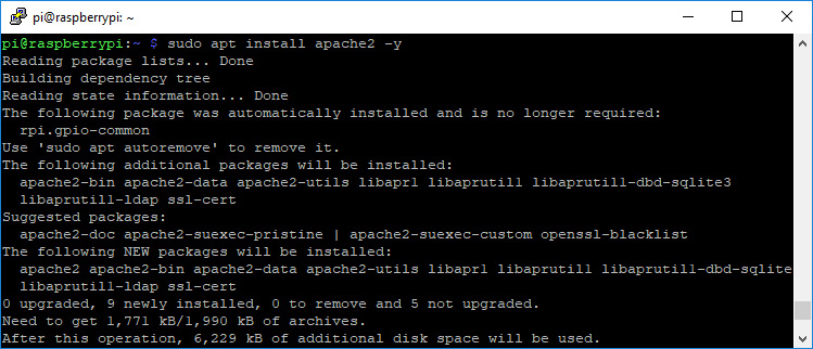
Figure 8.25 – Installing Raspberry Pi Apache2
Once this command runs successfully, Apache will be installed. Now, to test this installation, you just need to do the following:
- First, change the directory to /var/www/html. Just type the following command in the terminal:
cd /var/www/html
- This is the home directory of your server. All the source code for your website or web page will go in here. By default, an index.html file is present in this directory. You can easily access your server’s index file through your Raspberry Pi’s IP address. You can easily get the address by typing ifconfig or hostname -L in your terminal.
- Once you get the IP address, just type that address into any browser connected to the same network as your Pi. You should see the following output if everything has been installed correctly:

Figure 8.26 — Apache2 Debian Default Page (index.html)
With that, we have installed the Apache package. Next, we will install the PHP component.
PHP installation and setup
Hypertext Preprocessor (PHP) is a server-side scripting language that is used to develop dynamic web applications. To install PHP on your Pi, just type the following command in your terminal:
sudo apt install php -y
Now, let’s test whether it has been installed as expected. For this, we will replace the default index.html file with a file of our own. For this, just move to Apache’s home directory and type in the following commands:
cd /var/www/html
sudo rm index.html
sudo nano index.php
In your index.php file, add the following code to print a message of your choice on your web page. We will print the most basic message – "hello world":
<?php echo "hello world"; ?>
The following screenshot shows what this will look like on your screen:
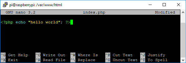
Figure 8.27 – Your first PHP script!
To save your file, press Ctrl + X, followed by Y, and press Enter to exit. Now, for the changes to take effect, we will restart the Apache server using the following command:
sudo service apache2 restart
To test this, just type in the IP address of your Pi on a browser. You should see an output similar to the following instead of the one you saw when you first installed Apache:
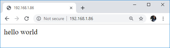
Figure 8.28 – Sample output page
If everything works as expected, then you have successfully installed and configured PHP on your Pi. Now, you can write PHP scripts that can be used to communicate with databases and client-side scripting language pages.
In the next subsection, you will learn how to install MySQL on your Raspberry Pi. Essentially, you will be installing a database server on your Pi that can be accessed through any device connected to the local network. Moreover, you will install another software component called phpMyAdmin, which is a GUI for accessing and managing the database.
MariaDB and phpMyAdmin installation
MySQL (SQL stands for Structured Query Language) is a popular relational database that is completely open source.
We will be installing the MariaDB server, which has been built on top of MySQL. First, we need to install MariaDB and the php-mysql package, which will allow us to use phpMyAdmin to manage our MariaDB database. Now, to install and set up everything, we need to run three commands, one after the other:
sudo apt install mariadb-server php-mysql -y
sudo service apache2 restart
sudo mysql_secure_installation
The first command will install the database server and the supporting package. Then, we need to restart the Apache web server so that it can detect the new packages. To complete the installation, we need to type in the third command, which will define the configuration:

Figure 8.29 – The mysql_secure_installation command’s output
As you can see, this command lets you secure your database using the credentials that you specify. Just follow these steps to complete this process:
- You will be asked to Enter current password for root. There’s nothing to add here, so just press Enter.
- Type in Y and press Enter to set the root password.
- Type in a password at the new password prompt and press Enter.
Important Note
Remember this root password as you will need it later.
- Type Y to remove anonymous users.
- Type Y to disallow root login remotely.
- Type Y to remove the test database and access to it.
- Type Y to reload the privilege tables.
When the installation is completed, you’ll see a message stating, Thanks for using MariaDB!. This can be seen in the following screenshot:
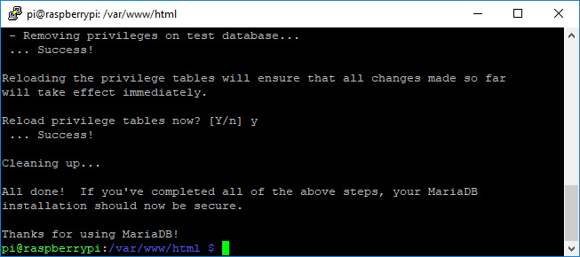
Figure 8.30 – MariaDB installation completion message
Next, we will install phpmyadmin on our system. To do that, just type the following command in your terminal:
sudo apt install phpmyadmin -y
The PhpMyAdmin installation program will ask you a few questions. We’ll use dbconfig-common to configure this. Then, follow these steps:
- Select Apache2 when prompted and press the Enter key.
- When asked Configuring phpmyadmin?, select OK and press Enter.
- When asked Configure database for phpmyadmin with dbconfig-common?, select Yes.
- Type your password and press OK:
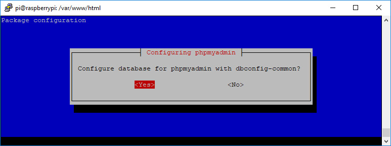
Figure 8.31 — phpMyAdmin configuration window
Now, we just need to enable the PHP MySQLi extension and restart Apache2 for changes to take effect. This can be done by using the following commands:
sudo phpenmod mysqli
sudo service apache2 restart
Now, we need to perform one final step before we can open the phpMyAdmin interface. We need to create a link that will allow Apache’s home directory to access the phpmyadmin folder. This can be done by the following command:
sudo ln -s /usr/share/phpmyadmin /var/www/html/phpmyadmin
Now, you will be able to see a phpmyadmin folder in Apache’s home directory. This means you can access the UI for this application just by typing the following address in any browser connected to the same network as your Raspberry Pi: <Pi’s IP Address>/phpmyadmin.
You should see the login page for phpMyAdmin open in your browser window, as shown in the following screenshot:
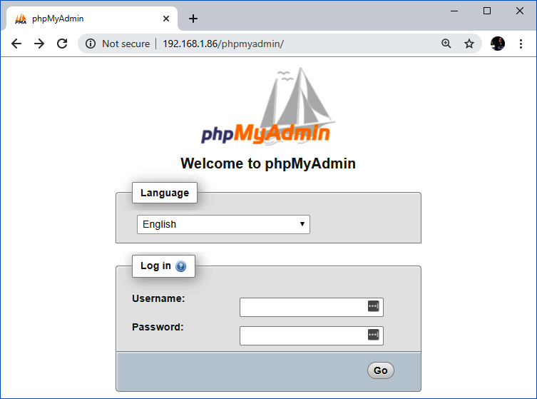
Figure 8.32 – phpMyAdmin login page
Enter the defined user credentials and press the Go button to log in:
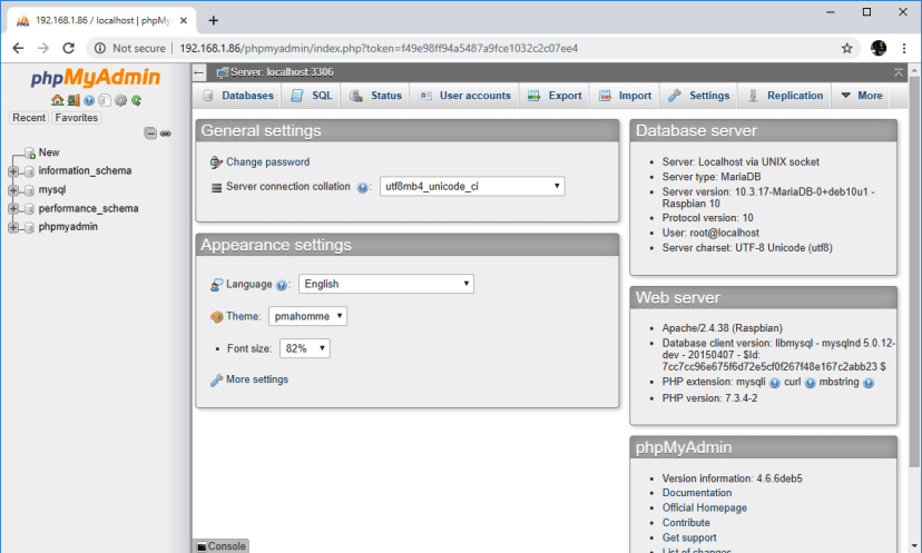
Figure 8.33 — PhpMyAdmin home page
With that, you have installed both the database and the database management component and, in turn, the LAMP configuration on our Raspberry Pi!
Now, you can use these software tools to create dashboards and access them through a web interface. This gives you immense customization options, but the tradeoff is that you need to know how to create web pages in any programming language of your choice.
Hence, this marks the end of our book. Now, let’s summarize what we have learned in this book.
Summary
We covered a lot of topics throughout this book and provided several projects to help you practically implement the knowledge you’ve gained.
You have learned a variety of essential skills throughout this book. For instance, you can now set up your own Raspberry Pi and you know what MQTT is, which means you can use this communication protocol in any of your projects. Furthermore, you have learned how to set up the Node MCU and ESP32 development boards and how to write efficient and robust code for them. At this point, you can build two fairly complex prototype projects on your own: an IoT Weather Station and a Smart Home control system!
After that, you learned the basics of Bash (the language used to write and execute Linux commands) and how to set up an online MQTT broker, either on an independent provider or on your very own virtual machine. Finally, you learned how to connect your IoT devices to AWS IoT and how to connect your LAMP server to your Raspberry Pi.
These are just some of the things you can do now. But this is just the beginning – keep learning and improving yourself!