
4
Node-RED on Raspberry Pi
This chapter will get you acquainted with very popular software for the Raspberry Pi – Node-RED. It is browser-based low-code programming software that allows beginners to create APIs and control the Pi hardware by creating flows, a connected component created by wiring several nodes together to perform a specific task. This chapter has four main sections:
- Introduction to Node-RED
- Node-RED first-time installation, setup, and demonstration
- Node-RED MQTT components and dashboard setup
- Mini project 2 – controlling a NodeMCU LED from the Node-RED dashboard
So, let's start with a basic introduction to what exactly Node-RED is.
Introduction to Node-RED
The website of Node-RED (https://nodered.org/) gives a perfect introduction to the purpose of using the software:
Node-RED is a programming tool for wiring together hardware devices, APIs and online services in new and interesting ways.
It provides a browser-based editor that makes it easy to wire together flows using the wide range of nodes in the palette that can be deployed to its runtime in a single click.
Hence, we can say that Node-RED is a UI-based programming tool that can be used to create various applications, which include hardware device control (Raspberry Pi GPIO access is also available), flow-based API development, and so on. We can run multiple flows at once and each of them will run independently.
Moreover, Node-RED allows the easy setup of several additional services, which would otherwise require a lot of work and experience. One such example is setting up a SQL database to store all the data arriving in Node-RED through any communication protocol, be it hardware-based (GPIO) or software-based (MQTT).
This software is so useful, especially for a device such as the Raspberry Pi, that it comes pre-installed when you flash the Raspberry Pi OS version with the recommended software. Additional Node-RED developments were made specifically for the Raspberry Pi. These include the following:
- You can access and control the Raspberry Pi GPIO from Node-RED.
- Due to the limited memory of the Raspberry Pi, you will need to start Node-RED with an additional argument to tell the underlying Node.js process to free up unused memory sooner than it would otherwise.
To do this, you should use the alternative node-red-pi command and pass in the max-old-space-size argument. Please note that this is browser-based software so when you run this locally on the Pi, you can access the console window from any device connected to the same network as the Raspberry Pi.
This section has given us an informative introduction to Node-RED. In the next section, we will first install and set up Node-RED on our Raspberry Pi and then create two simple flows to get some basic knowledge on how to use this software.
Node-RED first-time installation, setup, and demonstration
This section will cover in detail how to install and set up Node-RED on the Raspberry Pi. After that, two simple demonstration applications will be covered, which will show us the power of Node-RED and how it can be utilized to its full extent.
Node-RED installation
Installing and setting up Node-RED on your Raspberry Pi is a straightforward process. Please note that this section assumes that you have already set up your Raspberry Pi with the latest version of the Raspberry Pi OS with all the initial configurations. If that is not the case, please refer to Chapter 1, Introduction to Raspberry Pi and MQTT, for that.
First, access your Raspberry Pi as we will require the terminal window at the very least to install Node-RED on it. There are two ways to access your Pi:
- Through the desktop interface: It requires a monitor, keyboard, and mouse connected to the Pi.
- Through Secure Shell Protocol (SSH): SSH has to be enabled from Pi configuration to use this option. You can even use VNC (which stands for Virtual Network Computing) to access the whole desktop interface through your PC and use your PC’s mouse and keyboard.
You will need the terminal window regardless of the method you use for this setup process. Please note that you can use any software to SSH into your Raspberry Pi. Figure 4.1 shows the terminal window after you SSH into your Pi using Putty:

Figure 4.1 – Raspberry Pi terminal access through SSH (via Putty)
Next, we need to make sure that the Raspberry Pi OS is up to date. For that, just run the two commands given next in the order they are given. This will take some time, so I would suggest you go out for a walk or grab a snack in the meantime:
sudo apt update
sudo apt upgrade
You may need to restart your Pi for the updates to be installed. After this is complete, we can proceed to the actual software installation. As mentioned before, Node-RED comes pre-installed with the full OS image. But this may be using an older version of Node.js. To install/upgrade to the latest version of Node-RED (along with the dependencies), please use the following command:
bash <(curl -sL https://raw.githubusercontent.com/node-red/linux-installers/master/deb/update-nodejs-and-nodered)
This will walk you through the whole installation process, which will also install all the required dependencies for Node-RED. Just press Y to start the installation process (Figure 4.2):
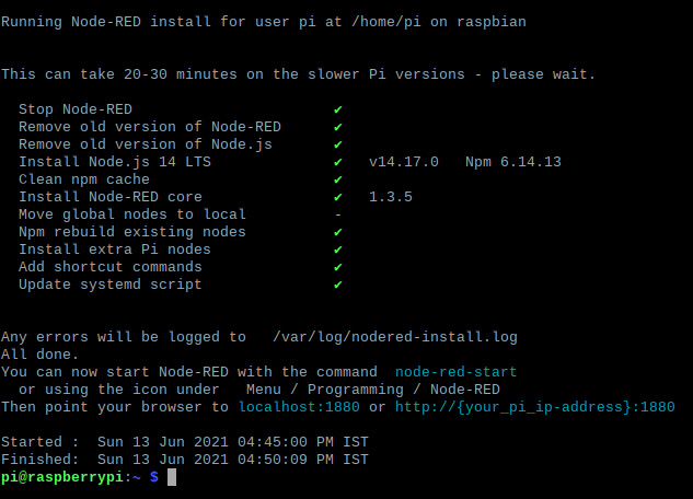
Figure 4.2 – Node-RED installation logs
Next, we will see how we start Node-RED on our Raspberry Pi, now that we have successfully installed it.
Running Node-RED on your Pi for the first time
There are two ways to start Node-RED, one through the desktop interface and the other through a terminal window. To start it through the desktop interface, just open the Node-RED application through the following path: Start Menu | Programming | Node-RED. This will open a terminal window with the node-red-start command pre-configured to run.
To start it through the terminal, just open a new terminal window and type in the following command:
node-red-start
Once you start Node-RED through any of the mentioned methods, wait a few seconds for the initialization process to complete. Once that is done, you will see a message flash on the terminal window saying: Node-RED has started, point a browser at <—IP address of Node-RED—>. This means that Node-RED is now active on the given IP address. The Node-RED server runs on the same IP address as that of your Raspberry Pi and on port 1880.
You can access Node-RED through any device browser that is connected to the same Wi-Fi network as your Raspberry Pi. This makes this service easily accessible across multiple platforms with the host being the Pi. To open Node-RED on any device, all you need to do is the following:
- First, connect to the Wi-Fi network to which your Raspberry Pi is connected (your device could be a PC, laptop, mobile phone, or even a smart TV!).
- Then, open a browser window.
- In the URL bar, type in your Raspberry Pi’s IP address (which you use to access it via VNC), followed by a colon, and then the port number for Node-RED, which is 1880. For example, if your Pi’s IP address is 192.168.0.23, then the URL you need to type in will be 192.168.0.23:1880.
In the next section, we will go through a crash course on all the basic functionalities and features Node-RED has to offer. The section will further cover two very simple and basic applications that will utilize the various functionalities of Node-RED.
Node-RED crash course
Now that we have Node-RED installed on our Raspberry Pi, we can further explore all the features and functionalities it has to offer. We will go about that in the following order:
- What do we see on the home screen?
- Understanding the following terms–node and flow
- Additional features
- Creating the Hello World flow
- Controlling an LED connected to the Raspberry Pi through Node-RED
Please note that this will give you an overview of how Node-RED works on the Raspberry Pi. So, let’s get started with the first point.
What do we see on the home screen?
When you open Node-RED on any web browser, you will see the home screen shown in Figure 4.3.
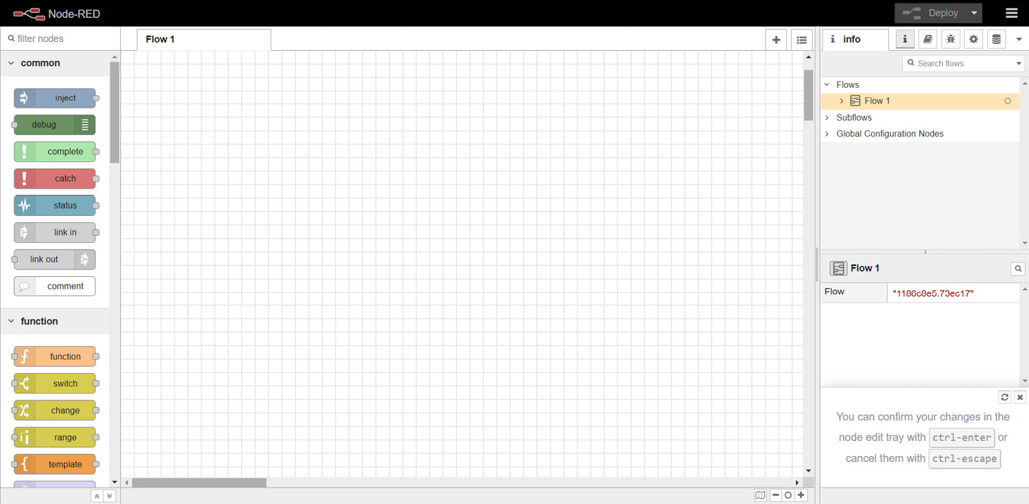
Figure 4.3 – Node-RED home screen
Now, to understand this screen better, we will divide the main screen into three components and go through each separately (Figure 4.4). The names of these components are shown next:
- Node palette
- Workspace
- Control panel

Figure 4.4 – Three components of the Node-RED home screen
Each part has its purpose and that is what we will be discussing in this section.
1 – Node palette
The node palette is a very important, essential component. It has all the nodes that can be used to create different flows with application-specific functionalities in Node-RED. We will discuss these terms in detail in the next subsection.
The palette is further segregated into different sections based on the category a particular node belongs to. This helps the user search for the right node easily. Each node has its required configuration. Some nodes can be used directly just by dropping them into the workspace and some require additional setup.
2 – Workspace
A major part of the home screen is occupied by the workspace. This is the area where we create our flows. We drag all the nodes we require for a particular application from the palette to the workspace and connect them in a particular order to create a flow (which can be interpreted as a program).
3 – Control panel
This is the last component of the Node-RED home screen. This panel has several tabs, each serving a particular purpose. We will be discussing the important tabs, as follows:
- It has the Info tab, which contains information such as how many flows the workspace has, what nodes are used in each flow, and so on.
- The Help tab gives information about each node, which includes several things, such as a short description of the node, how to use the node in a flow, and so on.
- The Debug tab opens the Debugging panel where the debug information of each node is visible (it can be configured in a flow using the debug node).
- The Dashboard tab is also accessible through this component. It gives information about the components and the dashboard can be opened from this section (note that this tab is not visible in the preceding figure as we need to install the Node-RED dashboard extension).
Understanding the following terms–node and flow
The following are explanations of the terms:
- Node: We will use a very simple analogy to understand what a node is. Whenever you write code for an application, you create several functions to make the code more readable and efficient. The nodes are different functions, with each node having particular functionality.
- Flow: Continuing with the preceding analogy, when we use multiple nodes and join them to create a group of nodes performing a specific task, this group is termed a flow. This is like the code written for that task but instead of code, we use Node-RED’s drag and drop feature to create a flow performing the same task.
Additional features
In addition to the basics that we just covered, there are ample additional features. A major feature is the ability to “install external node extensions.”
That opens a lot of new development opportunities, which include connecting Node-RED to databases, external services such as IFTTT (If This Then That), Twilio, and so on. The main advantage is that in most cases, no external tech stack knowledge is required. The setup is minimal, such as entering some required information. For example, to connect to a SQL database through the MySQL extension (this will be covered in detail in later chapters), you have to just enter the IP address on which the database is hosted, its port, database name, and user credentials. There is no need to write a single line of code.
There is an extensions library hosted and managed by www.nodered.org. We can access that through the Node-RED home page through the additional options, which can be accessed by clicking the three-line icon on the top-right portion of the screen (Figure 4.5):

Figure 4.5 – Additional options section on the Node-RED screen
This concludes this section. Next, we will be creating two simple flows, which will help us understand how to operate Node-RED.
Creating the “Hello World” flow
In this section, we will be creating our very first flow with Node-RED. This flow will perform a very simple task:
Every time we trigger the flow, the current timestamp value will be printed on the debug screen (in the control panel).
To create this flow, we will require two nodes: the inject node and the debug node. Just drag these nodes from the node palette onto the workspace once. When this is done, your screen will look like what’s shown in Figure 4.6.
Important Note
We need to deploy every time we make any changes in any of the Node-RED flows. Every added or updated node will have a light-blue dot on top, indicating that these changes will only be reflected when we redeploy the flows (dots visible in Figure 4.6).

Figure 4.6 – Add the nodes required to create our first flow
The next step is to connect these nodes. To do that, just take your cursor to the gray dot on the inject node and then drag the line that emerges when you click and hold the left mouse button to the debug node’s gray dot. This will connect these nodes.
This is all for this flow as no additional setup is required for either node. Now, if you click the inject node, nothing will happen. To use this flow, we need to deploy the updated flows. To deploy the flows, all we need to do is click the Deploy button situated on the top-right side of the screen. Once that is done, we are all set to test our first Node-RED flow!
Testing this flow is very easy. Just open the Debug tab from the control panel and then click the inject node. Clicking the blue button on the inject node will trigger the flow and the timestamp value will be printed on the Debug tab (Figure 4.7):
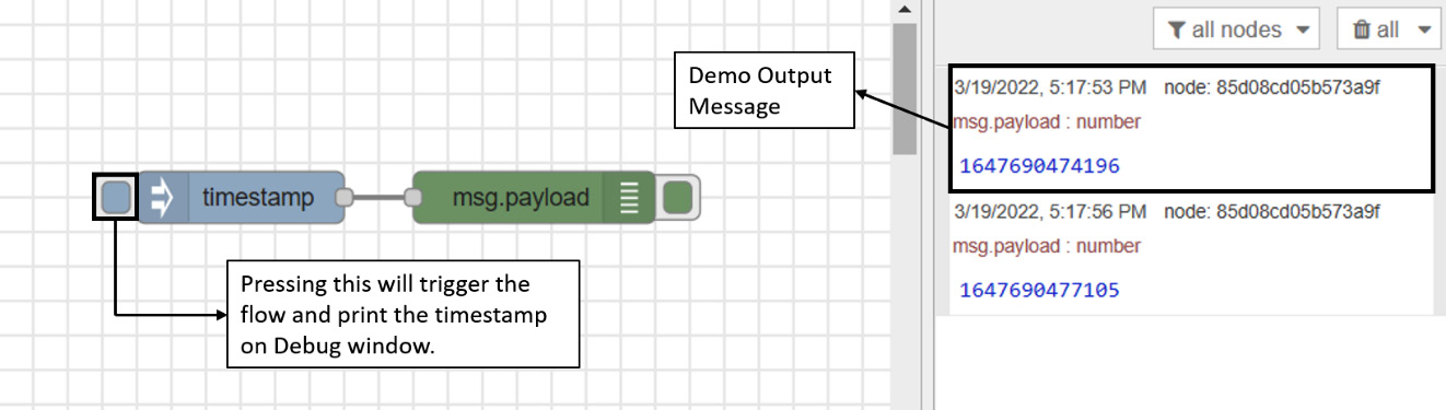
Figure 4.7 – First flow’s output demonstration
This was the basic version of this flow. There are a few improvements that can be applied to this flow. For instance, instead of having to manually click the inject node to trigger the flow every time, you can automate this process so that the flow is automatically triggered after a certain interval. Moreover, instead of printing the timestamp on the Debug tab, we can print anything we want. So, we will modify this flow so that it automatically prints the infamous Hello World! string after every 10 seconds. All we need to do is make some changes in the inject node.
To do that, just double-click on the inject node, which will open an edit window. There are several customizations possible that differ from node to node. For our case, we will be making two changes:
- First, we will change the return value from timestamp to a custom string of our choice.
- Second, we will set up an interval of 10 seconds to trigger this node.
Refer to Figure 4.8 to make these changes:

Figure 4.8 – Changes made in the inject node
Once these changes have been made, just redeploy the whole flow and see the new flow in action. Now, you will see the Hello World! string printed in the Debug tab every 10 seconds (Figure 4.9):
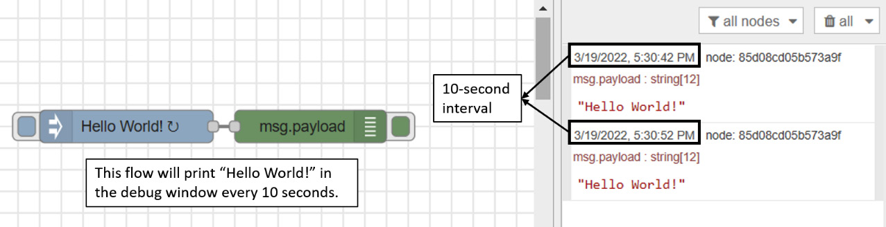
Figure 4.9 – Output of the updated flow
In the next section, we will create a flow to control the Raspberry Pi GPIO.
Controlling an LED connected to the Raspberry Pi through Node-RED
In this section, we will create a flow that will let us control a Raspberry Pi GPIO pin using the flow’s UI. First, drag the following nodes onto the workspace window:
- Two inject nodes
- An rpi – gpio out node (found in the Pi-specific nodes section):
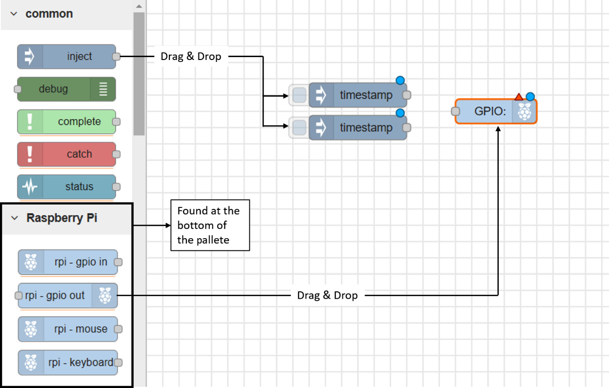
Figure 4.10 – Node-RED components for this flow
Next, we have to configure the nodes according to our requirements. These configurations include the following:
- Renaming the inject nodes and sending a Boolean True or False value according to the name given to it.
- Specifying which RPi GPIO we would like to configure with the GPIO node. In this case, we will choose GPIO18 (Pin 12).
Please refer to Figure 4.11 for the necessary configurations:

Figure 4.11 – Node configurations for each component of the flow
These were the required software configurations. In terms of hardware setup, you will need the following components:
- A 100–330-ohm resistor
- An LED
- A breadboard
Now, connect the hardware circuit using Figure 4.12 as a reference.
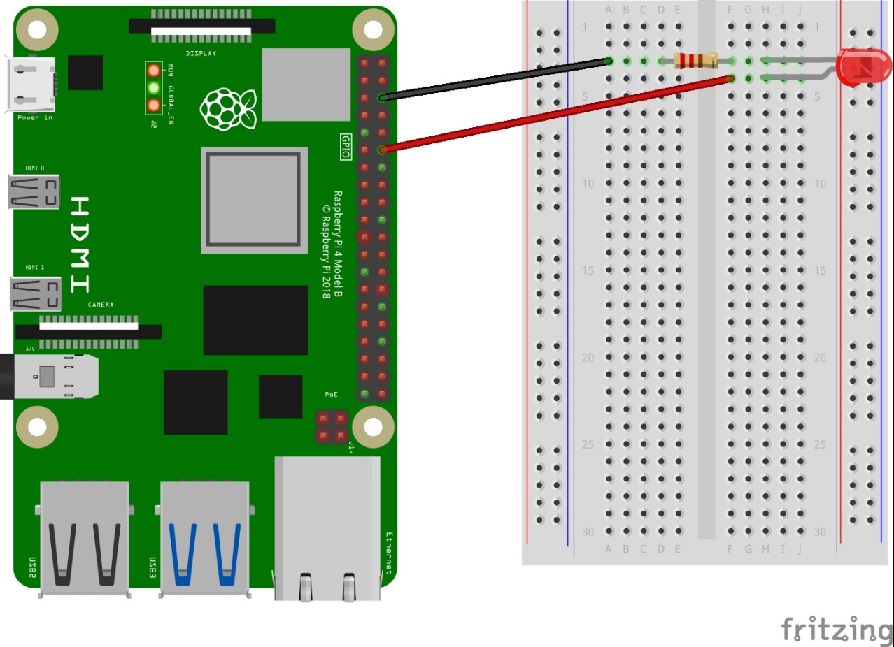
Figure 4.12 – Raspberry Pi LED connection schematic diagram
This completes all the required setup procedures. Now, just deploy the flow from the Node-RED home screen and you will now have the functionality to control the LED via Node-RED.
This is just a basic demonstration of Node-RED. Using different extensions and customizations, creating even complex projects is straightforward compared with the conventional coding alternatives that require programming knowledge. But it is important to note that for complex applications, you may need to write some custom functions in Node-RED that need to be coded in the JavaScript programming language (as Node-RED is based on Node.js). But for simple to intermediate-level projects, creating flows and customizing nodes is enough.
The next section will introduce you to the Node-RED dashboard. It is an interactive dashboard creation tool that will let you use different widgets such as switches, sliders, and gauges to create an interactive UI for the control and monitoring of your projects.
Node-RED MQTT components and dashboard setup
This section will start with an introduction to the dashboard and MQTT functionalities of Node-RED. That will be followed by a simple project in which we will connect an LED to a NodeMCU development board and demonstrate control capabilities through the Node-RED dashboard. So, let’s get started.
Node-RED MQTT nodes
The MQTT communication protocol was discussed in detail in the previous chapters. In this section, we will be seeing how can we use MQTT nodes in Node-RED. In Node-RED, you can find two MQTT nodes in the network section:
- The mqtt in node
- The mqtt out node
Please refer to Figure 4.13 to see where you would find the MQTT nodes in the node palette:

Figure 4.13 – MQTT nodes under the network section in the node palette
As the names suggest, the mqtt in node is to capture data coming from various topics (basically for monitoring) and the mqtt out node is to publish data on a particular topic (for control).
The following parameters are required and need to be configured for both nodes:
- Server: The IP of the MQTT server we need to use. In our case, we will be using the local MQTT server (localhost) hosted on our Raspberry Pi.
- Topic: The topic to which the node has to subscribe (to fetch data) or publish.
- QoS: This was discussed in detail in the last chapter.
Please take a look at Figure 4.14, which shows the edit options for both the in and out nodes:

Figure 4.14 – MQTT in and out nodes’ required configurations (marked)
There are several customizations when we want to add a new MQTT server. The main requirement is the server’s IP address and the rest is optional (note that by default, the port is 1883, but this is different if we use SSL). The customizations include the MQTT version, client ID (autogenerated if kept blank), username and password in the Security tab, and some messages that are triggered when a client connects or disconnects from a topic.
Please refer to Figure 4.15 to see the configurations available when adding a new MQTT broker for Node-RED MQTT nodes:
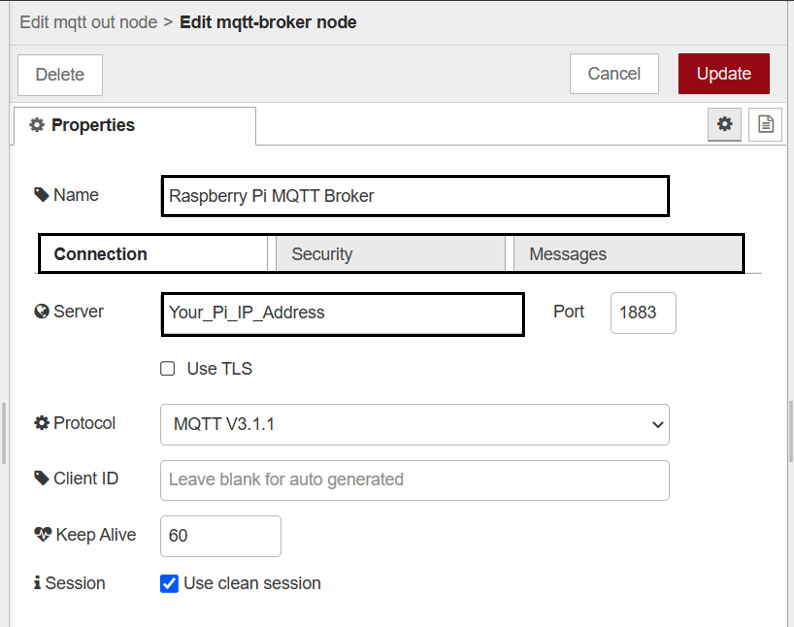
Figure 4.15 – Customizations available when adding a new MQTT broker
Next, we will cover the Node-RED dashboard installation, setup, and explanation. Please note that this is why we are using Node-RED, and hence, this is one of the most important sections of this chapter.
Node-RED dashboard
The Node-RED Dashboard is a module that provides a set of nodes in Node-RED to quickly create a live data dashboard. To learn more about the Node-RED Dashboard, you can check the following links:
Node-RED Dashboard site: http://flows.nodered.org/node/node-red-dashboard
GitHub: https://github.com/node-red/node-red-dashboard
There are two ways in which you can install this module. The first and the most straightforward way is to install it through the Node-RED UI. To do that, just go to options (the three horizontal bars on the top-right portion of the screen), then select Manage palette, and search node-red-dashboard in the Install section. You will see several options in the search results. Just click install for the first module (Figure 4.16). You have successfully installed the Node-RED Dashboard on your Pi:
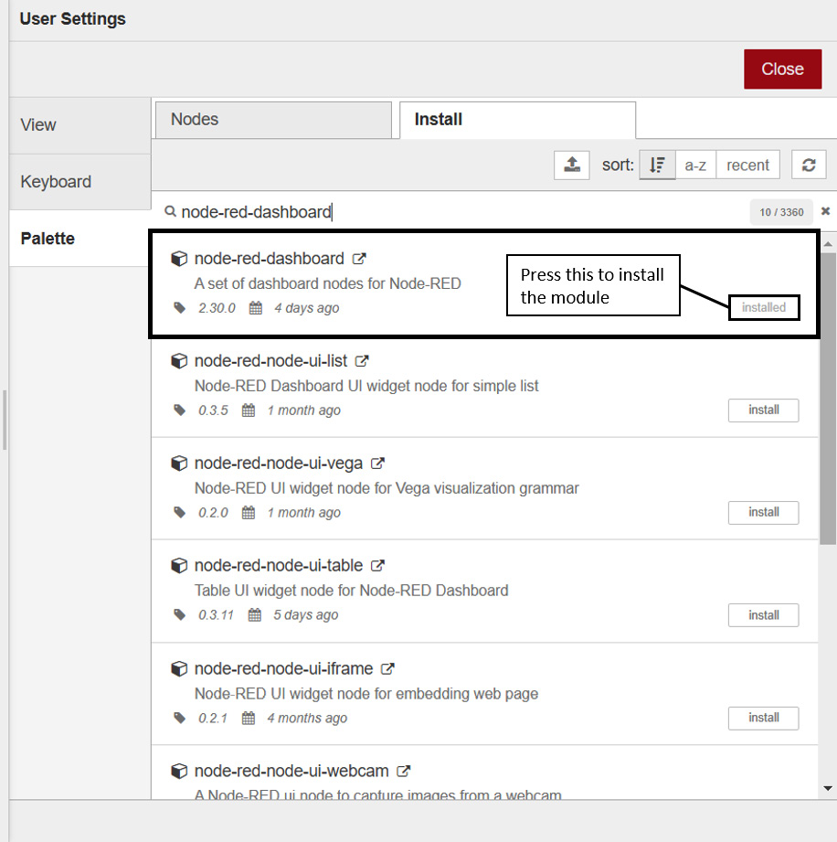
Figure 4.16 – node-red dashboard installation from the Node-RED UI
Alternatively, you can install node-red-dashboard through the terminal using Node package manager (npm). For that, just type in the following commands in the same order:
node-red-stop
cd ~/.node-red
npm install node-red-dashboard
The first command will stop Node-RED if it is already running. After that, we need to move to the node-red directory to install any additional modules through npm, which is exactly what the second command does. After that, just install node-red-dashboard using the third command.
This will create a node-red-dashboard folder in the node-red directory where all the files related to the dashboard will be stored. To open the Node-RED UI, type your Raspberry Pi IP address in a web browser followed by 1880/ui, as shown next:
http://<YourPi'sIPAddress>:1880/ui.
There will be two new additions on the Node-RED home screen. First, new nodes will be added to the node palette under the dashboard category (Figure 4.17):

Figure 4.17 – dashboard nodes in the node palette
Moreover, there will be a new dashboard section in the control panel. This section will let us manage the layout, theme, or site of our dashboard. We will discuss these in detail now:
When you open the dashboard pane on the control panel from the tabs located on the left side of the screen, you will see the options shown in Figure 4.18:
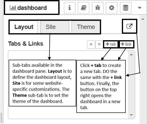
Figure 4.18 – The dashboard pane
By default, we are in the Layout sub-tab. Here, we can create different dashboard tabs and add all the UI elements to the desired tab according to our requirements. To add a new tab, just click the + tab button and a new tab will appear in the Tabs & Links window. Now, whenever you add a new UI node, you can select which tab (or group, to be more specific) it belongs to. You can even see the same element in this window and we can drag it from one tab to another if required. Different tabs can be accessed through the menu bar (the three-bar icon) on the dashboard (we’ve created two dummy tabs for the demo).
To demonstrate the dashboard in action, I have added two switch nodes from the Dashboard section and added them to two different groups, each in a separate tab. Please refer to Figure 4.19 to see how you will be able to access different tabs when you open the dashboard:

Figure 4.19 – How to switch tabs in the Node-RED dashboard
There are several other customizations in nodes, such as their size and other application-specific information. For example, consider a Gauge widget, which can be used to graphically display any incoming value. We can select the heading of this widget, the range, the value format, and even the unit that will be shown on the dashboard. Hence, we have highly customizable widgets, which help us build an interactive dashboard.
This concludes this section. In the next section, we will be utilizing all the knowledge we have learned so far to create a mini-project where we will be controlling the onboard NodeMCU LED using a switch widget on our Node-RED dashboard.
Mini project 2 – Controlling a NodeMCU LED from the Node-RED dashboard
The project’s aim is to control the onboard NodeMCU LED using a switch widget on our Node-RED dashboard, where we will be using MQTT as our primary communication protocol. We will proceed step by step, covering the hardware requirements, software setup, code explanation, and project demonstration.
Let's first start with the hardware requirements for this project.
Hardware requirements
This is a very simple project so the hardware requirements are quite straightforward:
- A NodeMCU development board
- A Raspberry Pi
Information about both these devices has been covered in detail in the previous chapters. In the later sections, device-specific instructions that need to be followed will be listed.
Software requirements
As for the software requirements, only the Raspberry Pi needs to be considered as the NodeMCU code explanation will come later.
The following should have been installed, set up, and configured in the Pi:
- Raspberry Pi OS setup (refer to Chapter 1, Introduction to Raspberry Pi and MQTT)
- Mosquito MQTT package installation and setup (refer to Chapter 1, Introduction to Raspberry Pi and MQTT)
- Node-RED installation and configuration (covered in the earlier sections of this chapter)
Please note that all these steps have already been performed if you have been following the book. If any of these steps are left to do, please refer to the chapters mentioned previously to complete them.
Hence, we are good with the software setup too. Next, we will move on to the NodeMCU- and Raspberry Pi-specific setups.
NodeMCU setup
As far as NodeMCU is concerned, no external sensors or actuators need to be connected for this project. Hence, we just need to write and upload the code specific to this project.
We will now start with the code walk-through and explanation.
Code explanation
The code for this project is pretty straightforward. This code does the following:
- Connects to an MQTT server (the Pi’s server in this case)
- Subscribes to the project2/led topic
- Changes the on-chip LED state according to the value received on the preceding topic
- Reconnects to the MQTT server if it disconnects
Now, we will cover the code in parts for better understanding. If you notice, the code is quite similar to the code written in Chapter 2, MQTT in Detail. The reason for that is the MQTT connection from the NodeMCU side remains the same. We are changing how we interact with our node (we used the terminal in Mini-Project 1 and now we will be using the Node-RED Dashboard UI). So, let's start with the code explanation.
Importing the required libraries:
#include <ESP8266WiFi.h>
#include <PubSubClient.h>
The first two lines of the code import the required libraries. The ESP8266WiFi library is used to access Wi-Fi networks, which grants the board internet access. The Pubsubclient library is the MQTT client library, which helps us run an MQTT client on the development board:
Important credentials and variable declarations:
const char* ssid = "wifi_ssid";
const char* password = "wifi_password";
const char* mqtt_server = "pi_ip_address";
WiFiClient espClient;
PubSubClient client(espClient);
unsigned long lastMsg = 0;
#define MSG_BUFFER_SIZE  (50)
char msg[MSG_BUFFER_SIZE];
int value = 0;
The next three lines are constant variable initializations for the Wi-Fi name, password, and the MQTT (pi) IP address. The Raspberry Pi’s IP address is the IP address of the broker.
The next few lines deal with the various object and variable initializations required later in our code:
Wi-Fi setup function:
void setup_wifi()
{
  delay(10);

  Serial.println();
  Serial.print("Connecting to ");
  Serial.println(ssid);
  WiFi.mode(WIFI_STA);
  WiFi.begin(ssid, password);
  while (WiFi.status() != WL_CONNECTED)
  {
    delay(500);
    Serial.print(".");
  }
  randomSeed(micros());
  Serial.println("");
  Serial.println("WiFi connected");
  Serial.println("IP address: ");
  Serial.println(WiFi.localIP());
}
The setup_wifi function is used to connect to the Wi-Fi network whose credentials we provided as SSID and password constant variables.
Callback function for handling MQTT subscribed topics:
void callback(char* topic, byte* payload, unsigned int length)
{
  Serial.print("Message arrived [");
  Serial.print(topic);
  Serial.print("] ");
  for (int i = 0; i < length; i++) {
    Serial.print((char)payload[i]);
  }
  Serial.println();
// LED On Off Logic
  if ((char)payload[0] == '1') {
    digitalWrite(BUILTIN_LED, LOW);
  }
 else
 {
    digitalWrite(BUILTIN_LED, HIGH);
 }
}
The callback function is used to print out the data received on the subscribed MQTT channels. In this case, we are subscribed to the project2/led topic, to which we will be sending data to control the onboard LED. We have programmed the function such that if it receives '1' on the topic, the LED turns on, and if it receives zero on the topic, it turns off:
MQTT reconnect function:
void reconnect() {
  // Loop until we're reconnected
  while (!client.connected()) {
    Serial.print("Attempting MQTT connection...");
    // Create a random client ID
    String clientId = "ESP8266Client-";
    clientId += String(random(0xffff), HEX);
    // Attempt to connect
    if (client.connect(clientId.c_str())) {
      Serial.println("connected");
      // resubscribe to the specific topic
      client.subscribe("project2/led");
    } else {
      Serial.print("failed, rc=");
      Serial.print(client.state());
      Serial.println(" try again in 5 seconds");
      // Wait 5 seconds before retrying
      delay(5000);
    }
  }
}
The reconnect function is used to reconnect to the MQTT broker if there is a problem and the board disconnects. The reasons for this may be internet connection failure, duplicate client IDs, and so on.
This function tries to connect to the MQTT broker every 5 seconds.
Arduino code’s setup function:
void setup() {
  // Initialize the BUILTIN_LED pin as an output
  pinMode(BUILTIN_LED, OUTPUT);
  // Turn off the LED initially.
  digitalWrite(BUILTIN_LED, HIGH);
  // Serial port opened
  Serial.begin(115200);
  // Call the setup_wifi function
  setup_wifi();
  // Connect to the MQTT Server
  client.setServer(mqtt_server, 1883);
  // Define the Callback Function
  client.setCallback(callback);
  // Subscribe to this topic
  client.subscribe("project2/led");
}
This is the Arduino setup function. We set the built-in LED pin mode to output. Then, we initiate a serial connection with a baud rate of 115200. Next, we call the setup_wifi function to connect to the Wi-Fi network.
Next, we connect to the MQTT server, which in our case is the Raspberry Pi, and then we specify the callback function using the setCallback function of the Pubsubclient library:
Arduino Code’s Loop Function
void loop() {
  if (!client.connected()) {
    reconnect();
  }
  client.loop();
}
The final loop function is the one that runs indefinitely. First, we check whether the MQTT client is disconnected. If so, we run the reconnect function.
In addition to this, we resubscribe to the project2/led topic so if we send a 0 or 1, we can control the LED on NodeMCU.
This completes the NodeMCU part of the project. Next, we will cover the Raspberry Pi setup.
Raspberry Pi setup
For this project, it is assumed that you have already set up your Raspberry Pi. That includes the installation of OS, the MQTT package, and also Node-RED (with the node-red-dashboard module installed).
We have to do the following tasks for the Pi:
- Create a dashboard layout (this includes the creation of a tab and group) for the project.
- Create the project flow and deploy these changes.
So, let’s get started with the dashboard layout setup.
Dashboard layout setup
In this section, we will be creating a simple dashboard for this project on Node-RED. It will consist of a single tab with a switch widget, which will be used to control the NodeMCU onboard LED. To do this, just follow the step-by-step tutorial listed next:
- Open Node-RED on your browser of choice. Then navigate and open the dashboard section from the control panel. The control panel is situated on the right side of the screen. Take a look at Figure 4.20 for reference:
Figure 4.20 – The dashboard section in the Node-RED control panel
- Next, click on the + tab button and then click on the edit button, which will appear when you hover your mouse pointer over the tab. In the edit window, rename the tab to what you want (I have simply named it Project 2) and then click the Update button. Refer to Figure 4.21 for reference:

Figure 4.21 – Creating a new tab and renaming it
- Next, we need to create a group in the tab as all the widgets we use in our flow need to be assigned to a particular group. We will create a new group using the + group option, which appears when you hover over the tab.
- Just clicking it will create a new group, which needs to be renamed as well, using the same process as for the tab. I have named the group NodeMCU. See Figure 4.22 for reference:
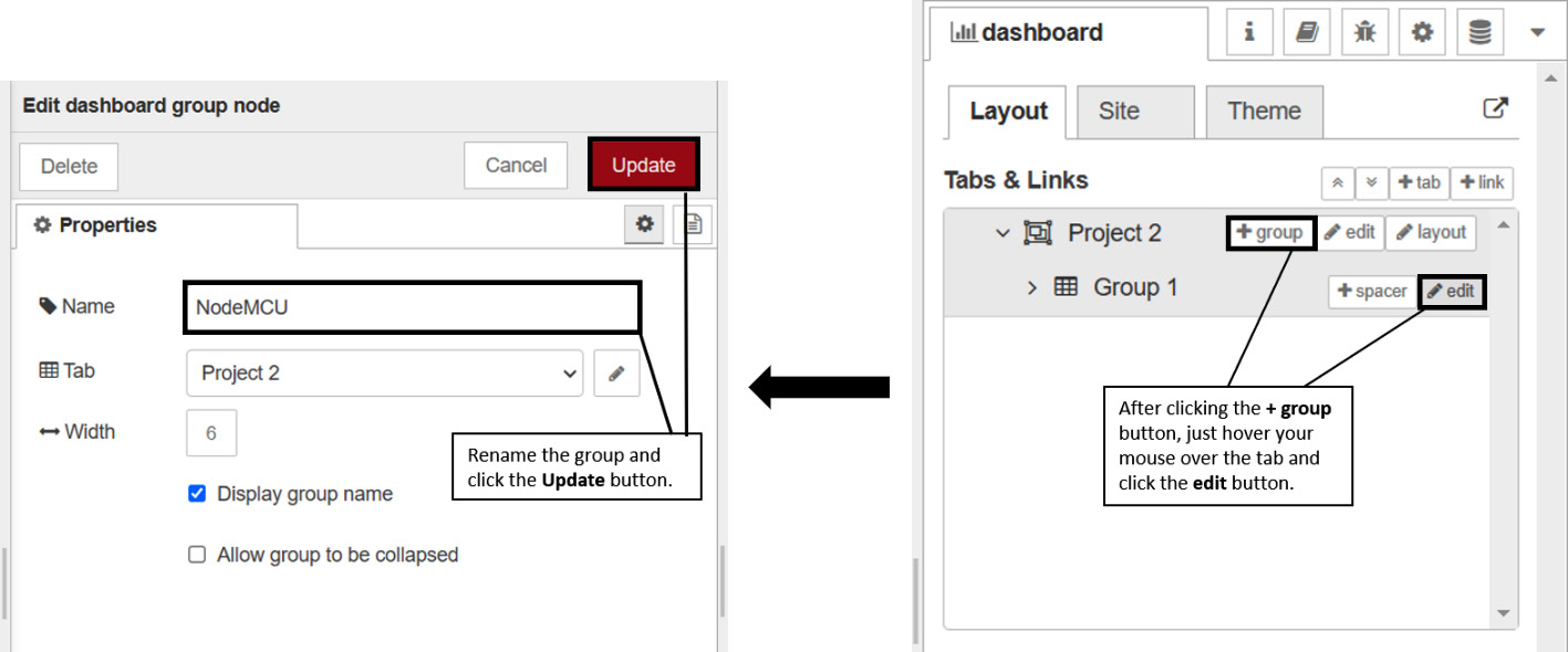
Figure 4.22 – Adding a new group to the tab and renaming it
This completes the dashboard layout setup. We only require a single group for this project as we will be adding only a single widget.
Next, we will create the flow for this project.
Project flow
We will be creating a simple flow that performs the following task:
It will create a switch widget on your dashboard, which will send 0 and 1 on and off positions respectively, and this message will then be published on the project2/led topic as payload.
Let's start creating the flow. Just follow these steps:
- Drag two nodes from the node palette. The node names are as follows:
- The switch node under the dashboard section
- The mqtt out node under the network section
Please refer to Figure 4.23 for reference:
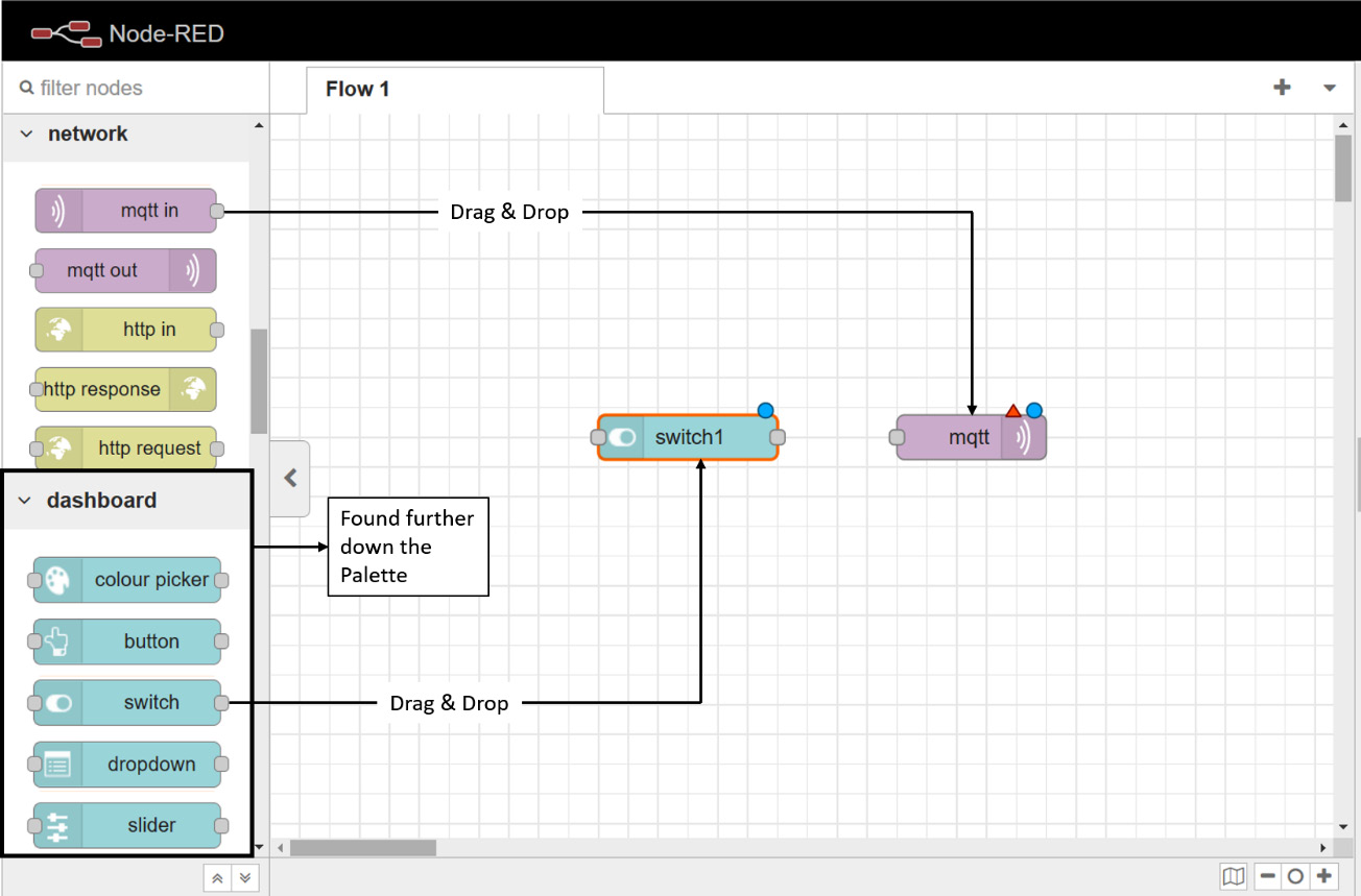
Figure 4.23 – Drag and drop the project flow components onto the workspace
- Connect the switch node to the mqtt out node by dragging a wire across both. We will now have to configure the nodes for our project. Please note that the following customizations for each of the two nodes will be required to complete the flow:
- The switch node will require the Group, Label, On Payload, Off Payload, and Name sections to be changed.
- The mqtt out node will require the Server and Name to be set up.
Please refer to Figure 4.24 to complete the listed customizations and, hence, the flow for this particular project:

Figure 4.24 – Project flow setup for mini project 2
This completes the project flow setup for this project. Just deploy this flow by clicking the Deploy button situated on the top-right side of the screen. Now, to view our dashboard, just open the Node-RED dashboard using the link mentioned earlier in the chapter. Our dashboard will only have a single tab, and on it, we will find a single switch situated in the middle of the screen. Refer to Figure 4.25 to see what our dashboard will look like:
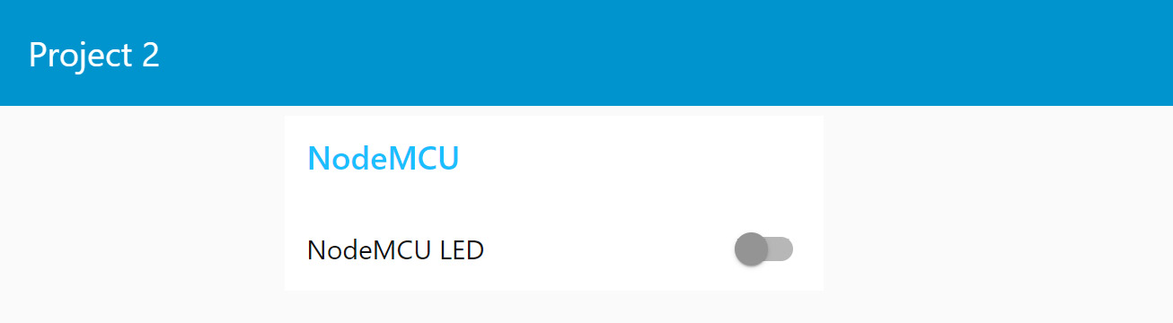
Figure 4.25 – Mini Project 2 Node-RED dashboard
You will now be able to control your NodeMCU’s on-chip LED through the switch on the dashboard. This is just a small demonstration of what this platform can do. This is the end of this chapter’s last section.
Summary
This chapter mainly focused on a single piece of software that we will be using a lot throughout this book – Node-RED. We started with an introduction to this software, followed by a tutorial on how to install/update it to the latest version on our Raspberry Pi. After that, we had a crash course on the basics of how to use it to its fullest extent. Next, we covered the MQTT components of Node-RED (the nodes specifically) and installed and got acquainted with the Node-RED dashboard. Finally, we wrapped up by creating a mini-project wherein we controlled the onboard NodeMCU board wirelessly through a simple dashboard hosted on the Raspberry Pi.
Now that we have covered all the building blocks for this book (Raspberry Pi, MQTT, and Node-RED), in the next chapter, we will be creating our first major project: a weather station based on NodeMCU. This project will have a far more complex and interactive dashboard and it will show us just how powerful and easy to use Node-RED is.