
So here we are in the second-to-last chapter of the book. We’ve dug into the Pi’s hardware, we’ve learned a lot of WiringPi, and we’ve learned quite a lot of Linux system administration and programming. Hopefully you’ve seen the Pi’s strengths (and weaknesses) as a platform for your gadget. I know, however, that some of you aren’t convinced. What if, for example, you need more than one timer/counter? What if you need to be sure it doesn’t skew its timing with the system clock? What if you’ve invested a lot of time and effort writing cycle-accurate AVR assembly for a particular project, but you want the extra compute power of the Pi, or Internet access? What if your circuit really needs 5v GPIOs? If you’re one of those folks, this project is for you.
Best of both worlds
Bugs
We’re digging into other people’s code, and inevitably, there are at the time of this writing (late January, 2018) a couple of bugs. I mentioned quite a while ago that WiringPi applications do not need to run as root. This is because the Pi foundation has extended access to the system components that drive the GPIO pins into user space (where our programs live). Unfortunately, in doing so, they introduced a bug. When a program requests access to the GPIO ports as a non-root user, it takes the system a certain amount of time to set things up. The request should block (remember blocking from our discussion on threads?), but it doesn’t. The WiringPi library has delays built-in to take care of this. Unfortunately, the version of AVRDUDE available to the Pi with apt-get does not. There is a patch for AVRDUDE, but as of this writing, you have to build AVRDUDE from the source code to get it. We’re not going to do that, because there’s an easier workaround. We’ll set AVRDUDE to run with root privileges when it runs, so that the mechanism’s timing won’t matter. It’s a security risk, but a reasonable one, in my opinion, as you can always disable or uninstall AVRDUDE once you’re happy with the sketch on the ATmega.
The Stuff You Need
Your Raspberry Pi. Either model should work.
ATmega328P-PU. As far as I know, these only come in 20MHz flavor, which works fine at 16MHz.
16MHz full can oscillator.
The 74LVC245 octal bus transceiver. We’ll use it as a level shifter, to shift 5v signals down to 3.3v.
The generic LED, and a 220Ω dropping resistor for it.
The tactile button and a 10kΩ pullup resistor for the ATmega’s reset circuit.
Hookup wire, as usual.
The Circuit
Figure 12-2 shows the schematic of the circuit we’re building. Here’s how it works. The Pi’s 3.3v SPI signals are passed through the 74LVC245 where they remain at 3.3v, and are passed on to the ATmega. Even though the ATmega is running at 5v, its inputs are logical high at anything above 0.6v, so 3.3v is plenty. The ATmega will respond with 5v signals. These pass through the 74LVC245 and are lowered to the same level as the 74LVC245’s Vcc, which is 3.3v. No signal pin on the Pi ever sees more than 3.3v, so the Pi is safe. We run all the signals through the level shifter, because the ATmega’s SPI pins can become outputs running at 5v from program control. In fact, Blink, the program we’re going to test the setup with, will do exactly that to SCK, aka Digital13.
The 16MHz full can oscillator runs on 5v and outputs a 16MHz clock for the ATmega. Breadboards can be tricky for higher frequency signals, but I’ve run full can oscillators up to 20MHz on one with no problems.

Best of both worlds schematic
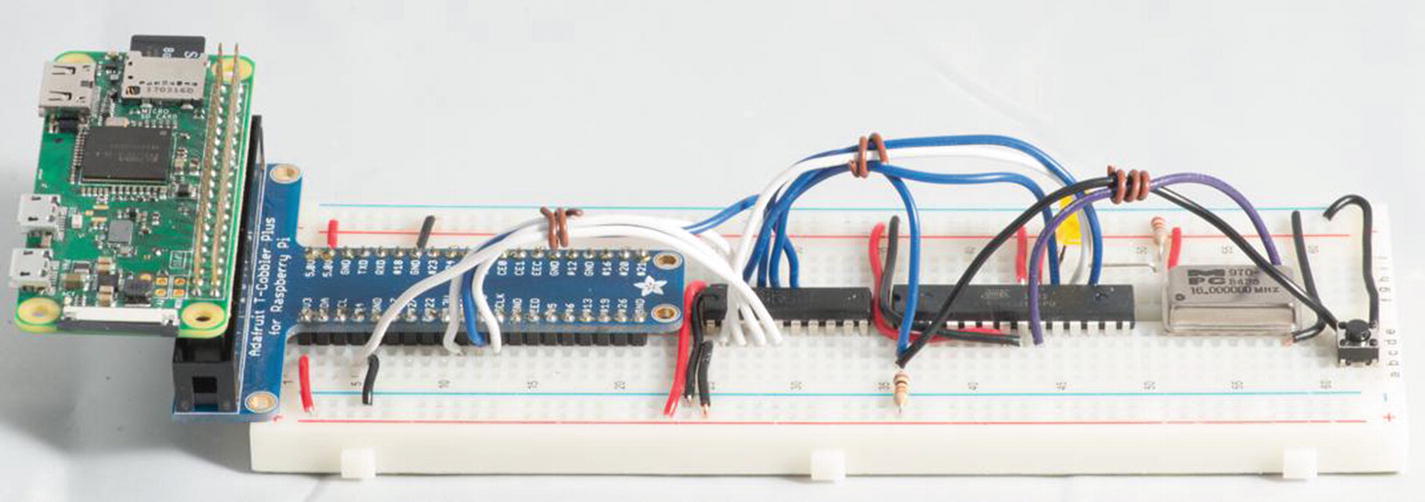
I find it easiest to wire the power and ground lines for everything first, so wire the 3.3v line from pin 1 on the Pi to one positive rail on your breadboard, and wire the 5v line on pin 2 to the other one. It is critically important that you not mix these two rails up, or you’ll be heading out to buy another Pi. To that end, I wired two grounds, even though they’re connected together inside the Pi: one from pin 4 to the ground rail on the 5v side of the breadboard, and one from pin 9 to the ground rail on the 3.3v side. You can see this organization on the breadboard in Figure 12-1.
Once that’s done, wire pin 20 of the 74LVC245 to the 3.3v rail of your breadboard and wire pin 10 to the ground. While we’re wiring the 74LVC245, let’s go ahead and hook pin 19 to the ground. This line is the /enable line, active low, that turns on the outputs of the 74LVC245. Likewise, connect pin 1, DIR, to 3.3v. This controls whether the 74LVC245 sends signals from its A pins to its B pins, or vice versa. Setting it high means signals go from A to B, which is what we want. Again, make doubly sure that all the connections between the 74LVC245 at this point are either to the 3.3v rail or to the ground.
We’ll set up the ATmega next. It needs +5v on pin 7 (VCC) and on pin 20 (AVCC) and on pin 21 (AREF). The first two are for its power needs. The last is the line against which analog inputs are compared. If you have a good reason, AREF could be connected to 3.3v, but normal Arduinos have these connected to Vcc. The ATmega needs two ground circuits as well, one on pin 8 and one on pin 22. It will not work correctly unless both sets of power connections are hooked up.
The last IC to connect is the 16MHz full can oscillator. While it only has four pins, it’s the same size as an 14-pin DIP and is often put in 14-pin sockets, so its pins are numbered as though it has 14 pins. Pin 1, the upper left, usually identified with a paint dot and by having the only square corner on the can, is not connected to anything. Pin 7 should connect to the ground rail. Pin 14 is connected to the 5v rail. The full can oscillator won’t work correctly at 3.3v.
Let’s do the /reset circuit next. Wire the 10kΩ resistor from the 5v rail to pin 1 on the ATmega. (It’s shown wired to the 3.3v rail in Figure 12-2, which also works fine.) Then run a wire from pin 1 to some free space on the board, put your tactile button there, and connect the other side of that button to the ground. When you push the button, you’ll short pin 1 to the ground for a moment, resetting the ATmega.
The LED circuit is the next one to do. Wire pin 19 of the ATmega to the cathode (+ side) of the LED. The anode of the LED gets connected to the 220Ω resistor, and through the resistor to the ground. This LED is active high.
All that’s left now are the SPI circuits. Run a wire from the Pi’s pin 19, aka BCM10, aka MOSI (remembering that this is a 3.3v signal) to pin 2, the A side of channel 1 of the 74LVC245. Then connect pin 18, the B side of the 74LVC245 to pin 17, aka MOSI (5v) on the ATmega. MOSI will come from the master (the Pi) through the 74LVC245’s a channel, to the ATmega’s MOSI pin.
The MISO pin is exactly the opposite of MOSI. Here I have to point out I did something a little unkind in the schematic. Look closely at pins 3 and 17 of the 74LVC245. You’ll see that I flipped the A2 and B2 pins (and their numbers) to make the schematic easier to read. The MISO circuit originates at the ATmega’s MISO (5v) pin, on pin 18, goes from the 74LVC245’s A2 (pin 3) to B2 (pin 17) channel, where its voltage is lowered, and ends on the Pi’s MISO pin, aka pin 21, aka BCM9 at 3.3v.
SCK/SCLK work the same as MOSI did. SCLK originates at the Pi (the clock circuit in SPI always comes from the master) at 3.3v, goes into pin 4 (channel 3’s A side) of the 74LVC245, and emerges on pin 16, (channel 3’s B side), where it connects to pin 19, aka SCK (5v), aka PB5, aka Digital 19 on the ATmega.
The reset circuit is next. For the ATmega to stop the running program and listen on SPI, it has to be reset at the right time, and we’ll use BCM4 (pin 7 on the Pi’s GPIO) for that job. It uses channel 4 of the 74LVC245 and is connected to the A side on pin 5, to emerge on pin 15, where it connects to the /reset circuit on pin 1 of the ATmega. When the Pi pulls BCM4 to the ground, the 74LVC245 will do likewise with the line to the ATmega, and whichever voltage (5v or 3.3v) we’re feeding the reset circuit to hold it high will be shorted to the ground by the 74LVC245, causing a reset, just as though we’d pressed the button.
All that’s left is the clock signal to the ATmega. Wire it from pin 14 of the full can oscillator (on the other side of the DIP from pin 1) to pin 9 (XTAL1) of the ATmega. We won’t use XTAL2 at all.
Powering Up
Go ahead and plug your Pi in and turn on its power, but make sure to check the temperature of the full can oscillator and the ATmega very quickly afterward. Don’t wait for the full boot up—the Pi’s power supply rails go live as soon as you give the Pi power. If either of these chips gets hot (and be careful, they can get too hot to touch), or the Pi doesn’t show signs of booting, disconnect the Pi’s power right now and go over their wiring again. Something’s not right. I’ve mixed up power connections on ATmegas many times, and once on a full can oscillator. If you’re quick, these ICs will usually live through the experience.
The Software
You need two pieces of software: the Arduino application and AVRDUDE. You should have the Arduino package already. If not, flip back to Chapter 4 and download it now. Don’t use the package you can get with apt-get. It’s horribly out of date.
You may recall from our discussions in Chapter 4 that AVRDUDE is part of the Arduino distribution. It is, albeit a very old version. We’re going to download a newer version that uses a driver that will talk to the GPIO port of the Pi. We’ll also hack the files of the Arduino application to use it. Go ahead and type sudo apt-get install avrdude. Like so:
Lots of stuff edited for brevity…
Setting Up AVRDUDE
Now that we have AVRDUDE installed system-wide, we need to do a couple things to it. We need to set up a local configuration for the Pi account, and we need to change the permissions it runs at. To set a local configuration, we need to create a file, in /home/pi, called .avrduderc. Note the dot (.) in front of .avrduderc—this tells Bash that this file should be invisible to ls without passing ls the -a flag. Long ago, in the dinosaur UNIX days, this custom of making configuration files in your account invisible was probably to keep people from stepping on them and making their accounts unusable. This would be particularly true of brand new users. The tradition still continues to this day. Go ahead and edit /home/pi/.avrduderc in Geany, or your favorite editor.
In order to be as flexible as it is, AVRDUDE lets the user define the properties of the programming device it’s expected to use. If you’ve poked around in the Arduino application and seen programmers like “Arduino as ISP” and so on, all of these and many others are possible, if AVRDUDE has code to drive them, and you tell AVRDUDE to use that interface and what to send on it. The version of AVRDUDE we just installed has an interface called linuxgpio, which is the standard Linux interface for talking to GPIO pins.
Local Configuration: .avrduderc
Here’s what you put in your /home/pi/.avrduderc file.
Declare the programmer id ("linuxgpio"), then provide a description so you know what you’re looking at next year. The type is also "linuxgpio". The reset pin is on 4, sck is on 11, mosi is on 10, and miso is on 9. Be sure to close every line with a semicolon (;), as well as the entire file. AVRDUDE is very fussy about this.
Hardware versus Software SPI
The linuxgpio programmer uses software SPI, via sysfs. Instead of going through spidev0, it controls the GPIO pins just like we could from WiringPi to bang out the pulses that make up SPI, by turning individual pins on and off. In the old days, this was called bit-banging, and it still is in some circles. It works. It’s not as fast, but the ATmega328P-PU only holds 32KiB of code, so it’s less an issue here than it would have been in the last chapter.
The advantage to this method is simply this: it works. There is hardware SPI programmer code in AVRDUDE 6.3—the most recent version you can get as of this writing without building the code yourself—but it seems to have the same timing bug I mentioned earlier, and I couldn’t find a good workaround for it. Software SPI will be fast enough. If you want your Pi to communicate with the ATmega via SPI (WiringPi has libraries for this), you may need to change the wiring slightly.
Fun with chmod
As mentioned, in order for AVRDUDE to do its job without being subject to the timing bug, it has to run with root privileges. While we could make it work with sudo, it would then want to use an .avrdude file in root’s home directory, and in any case it wouldn’t work with the Arduino application unless that too was running as root. And it touches the Internet. Bad idea. Instead, we’ll set a special permissions flag on the AVRDUDE executable that lets it run with the permissions of its owner. That flag is called SETUID. We set it with chmod.
The AVRDUDE executable lives at /usr/bin/avrdude. If you didn’t already know that, you could type which avrdude, and Linux would tell you. Then just type chmod u+s /usr/bin/avrdude. You can verify that it happened with ls –l /usr/bin/avrdude, and see the s flag set in the owner field. That’s your setuid flag.
Testing
Now, finally, we can test our build beyond “Is anything burning?” With AVRDUDE configured and set to run setuid, we can call it and ask it to say hello to the ATmega, and see if the ATmega answers. We do that with the avrdude command; pass it a –c and tell it to use the linuxgpio programmer that we just configured, then tell it the part number with -p. Here’s the demo:
Note particularly that it successfully read the ATmega, that it got a valid device signature (0x1e950f in hexadecimal), and that the fuses are okay. We’ll get back to fuses shortly. If you don’t get output similar to this (you can add the -v flag to get much more information), something’s wrong. If, instead, you get an error that the device signature is different from the expected one, and the device’s signature is actually 0x1e9514, you wound up with the ATmega328 instead of the ATmega328P-PU version, like I warned you about in Chapter 1. (I warned you about that so emphatically because I did it in preparation for this book. Buying the right IC is easier than hacking everything so an ATmega328 will work. If you did wind up with the wrong ATmega, this website has instructions for the aforementioned hacking: http://www.instructables.com/id/Bootload-an-ATmega328/ .
If you get a message that the device is not responding, it’s probably a wiring problem. If you get some other device ID, then you’ve got more complicated problems, and you need to make sure you’re using the linuxgpio programmer and not linuxspi. I got that message a lot while trying to make linuxspi work.
Setting Up the Arduino Application
Now that we have a working version of AVRDUDE, we need to set the Arduino application up to use it. There are three things we need to do, and all of them involve diving inside the Arduino application’s directories. Assuming your Arduino program is still in your Downloads directory like mine is (if you plan to use it regularly, you’ll want to move it to its own directory and run its install.sh script), cd to /home/pi/Downloads/arduino-1.8.5/hardware/tools/avr. Your Arduino version may change, and there’s a chance they may reorganize things (they do that from time to time), but this is where you look. This directory is hardware specific things, tools for hardware, specifically for the AVR family, which our ATmega328P-PU is a member of. If you type ls, you’ll see a number of directories that should make you suspicious, such as etc and bin. If you expect to find AVRDUDE itself in bin and avrdude.conf in etc, just as you’d find the system-wide AVRDUDE in /usr/bin and its configuration file in /etc/avrdude.conf, you’re absolutely right. The Arduino application mimics those paths inside itself for its captive, antique version of AVRDUDE, among other things.
We need to replace bin/avrdude with a symlink to the system’s AVRDUDE that we’ve worked on, and etc/avrdude.conf with a symlink to the system’s avrdude.conf. You can get the paths to the system versions by typing whereis avrdude.
Let’s replace the Arduino version of AVRDUDE with the system version first. We’ll do that using ln -s to make a symbolic link. Go into the bin directory (/home/pi/Downloads/arduino-1.8.5/hardware/tools/avr/bin) and remove the existing AVRDUDE. Then type ln -s /usr/bin/avrdude avrdude to create the symlink. The Arduino application will still call AVRDUDE in its own directory, but it’ll get the system-wide one. A quick ls -l avrdude will show whether the link worked correctly. If not, check to make sure you have the parameters of ln -s in the right order. It’s one of my favorite mistakes to make. You can also verify it by typing ./avrdude to call the AVRDUDE executable in this directory. You should get AVRDUDE 6.3 or higher. If you get version 5, you’re still looking with the version that came with the Arduino application, and it won’t do what you want.
Text deleted for brevity…
Next, we need to back out of the bin directory and do exactly the same thing in the etc directory with avrdude.conf. So type cd ../etc. This will take you up one level and then down into etc, all in one command. The, just like before, type rm avrdude.conf and ln -s /etc/avrdude.conf avrdude.conf. An ls -l avrdude.conf will verify that the link is where you want it.
The last thing we need to do to get the Arduino application set up is to add our new programmer, linuxgpio, to the programmer list in the application. That file is in the directory (again, assuming your Arduino application is still in Downloads) /home/pi/Downloads/arduino-1.8.5/hardware/arduino/avr and unsurprisingly, it’s called programmers.txt. Edit this file with your favorite Linux editor (Geany will work), scroll to the bottom, and add the following lines:
Save the file. You’re done tinkering with the guts of the Arduino application. Go ahead and start (or restart, as the case may be) the Arduino application. Select Tools ➤ Programmer, and Pi GPIO should show up in the list. Pick that. While you’re here, select Tools ➤ Board ➤ Arduino Duemilanove or Diecimila, and make sure the processor is set to ATmega328P. This is the simplest Arduino that uses the ATmega328P.
Setting Up the ATmega328P-PU
There is, as Steve Jobs used to say, one more thing. Normally, if you were setting up a new ATmega328P-PU to be an Arduino-compatible, you’d have to find (or make) a bootloader. We’re not going to. The bootloader really only does two things for you. It makes the Arduino listen for programs on its USART port and sets the fuses. If you try (or tried) to load a bootloader, you’d find that you get an error. Programmers are supposed to return a code when verifying a bootloader, but since our programmer is just a Linux device bit-banging SPI, it doesn’t know about that. Fortunately, we don’t actually need the bootloader at all. Since we’re communicating with the ATmega via SPI, we can load programs to it directly, although it will mean we can’t use Serial.print() in our programs meaningfully.
In fact, you could load programs into the ATmega right now, but if you did, you’d discover they run very, very slowly. To understand why, we need to talk about the fuses on the ATmega328P-PU .
Speed and Fuses
The fuses on the ATmega328P-PU are configuration settings. They’re persistent, even when the power’s turned off, and they determine how the microcontroller goes about its business. The whole listing is in the ATmega328P-PU’s datasheet, but it’s not one of the clearest parts of the datasheet. Instead, I suggest going here: http://eleccelerator.com/fusecalc/fusecalc.php?chip=atmega328p . Each fuse is called out by what it does, and if you click the right check boxes, you’ll get the configuration you want.
You can configure a lot of options: what voltage to consider too low to operate, whether reset is enabled or not, and so forth, but the options we’re interested in are the clock settings. By default, as the ATmega328P-PUs come from the factory, they’re set up to use their internal clock, at 8MHz, and divide that clock by 8. From the factory, they want to run at 1MHz, and it’s not an especially accurate clock. The Arduino software assumes we’re going to run at 16MHz (you can configure this for custom hardware, but it’s a big job). So uncheck the Divide Clock by 8 Internally option.
We also need to tell the ATmega328P-PU that we’re using an external crystal oscillator, that it’s faster than 8MHz, that it needs to wait 16K clock cycles on powerdown and reset before starting (to let the clock stabilize) and then 65ns (nanoseconds) beyond that. Or, if you scroll down further, check all the CKSEL (ClocK SELect) and SUT bits (Start Up Time) off. Note that like many things we’ve dealt with, ATmega configuration fuses are active low, so our resulting fuse bytes will have 1s for each bit we just set. The low-fuse byte should be (in hexadecimal) 0xFF (all bits high. inactive) the high-fuse byte should be 0xD9, and the extended fuse byte should be 0xFF. This would normally be in our bootloader. Since we don’t have one, we’ll just apply it by hand with AVRDUDE. It only needs to be set once. Type this:
It calls AVRDUDE, tells AVRDUDE that we’re going to specify a memory type (-U), specifies the memory type (lfuse, hfuse, and efuse, respectively), tells it to write, gives it the byte we want to set, and that this is a literal byte, not a filename or encoded in some way. It selects the part (m328p is the same as ATmega328P) and what programmer to use. You should get something like this:
AVRDUDE checked the device signature and wrote the low fuse, then verified that it was set correctly.
Likewise, AVRDUDE set the high fuse, read it back, and verified it.
And once more, AVRDUDE set the extended fuse, read it back, and verified it.
And we’re done.
Blink
After all this, let’s see if our handiwork actually works. Go to File ➤ Examples ➤ Basics ➤ Blink and select it. Don’t click upload. It won’t work. Choose Sketch ➤ Upload Using Programmer. Compiling will be slow, especially on a Raspberry Pi Zero W. After compiling the sketch, the Arduino application should call the system AVRDUDE, pick up the Pi account’s .avrduderc, upload the code and…the LED should flash. This is pretty much where we started with the Raspberry Pi, and now our Arduino-compatible is doing the job.
The Code
There isn’t much code in this chapter—just one new configuration file and some additions to the existing configuration files. The code from here on out? That’s up to you.
.avrduderc
Modifications to programmers.txt
Fuse Settings for the ATmega328P-PU
Conclusion
In this chapter, we built an Arduino-compatible and connected it to the Pi via SPI. We hit bugs, specifically that the Pi’s hardware SPI and AVRDUDE have a race condition (a place where timing matters and is not controlled) that means AVRDUDE can’t write to the ATmega over hardware SPI. We took a different tack, using software SPI and modified AVRDUDE. We tampered with the innards of the Arduino application and produced a solution that lets the Pi upload Arduino code to the compatible.
You could, going further, set up SPI communications between the Pi and the Arduino-compatible using hardware SPI like we did in the last chapter, and then use WiringPi’s SPI functions to communicate with the Arduino-compatible. If you need interrupts that take a known, predictable amount of time, this project would do the job for you. If you need to drive another Arduino project that requires 5v, this project would do that too. This chapter is all about adding to the flexibility of your Pi.
All that’s left are some conclusions.