
Chapter 8. Configuring Networking

This chapter covers the following subjects:
The following RHCSA exam objectives are covered:
Configure IPv4 and IPv6 addresses
Configure hostname resolution
Networking is one of the most essential items on a modern server. On RHEL 8, networking is managed by the NetworkManager service, and with the release of RHEL 7, some completely new tools were introduced to help manage networks. If you have already worked with networking on RHEL 6 and older, you will notice that networking has changed a lot and that some approaches that were the default in earlier versions will no longer work.
“Do I Know This Already?” Quiz
The “Do I Know This Already?” quiz allows you to assess whether you should read this entire chapter thoroughly or jump to the “Exam Preparation Tasks” section. If you are in doubt about your answers to these questions or your own assessment of your knowledge of the topics, read the entire chapter. Table 8-1 lists the major headings in this chapter and their corresponding “Do I Know This Already?” quiz questions. You can find the answers in Appendix A, “Answers to the ‘Do I Know This Already?’ Quizzes and ‘Review Questions.’”
Table 8-1 “Do I Know This Already?” Section-to-Question Mapping
Foundation Topics Section |
Questions |
|---|---|
1–2 |
|
3 |
|
4 |
|
5–8 |
|
9–10 |
1. Which of the following IP addresses belong to the same network?
I. 192.168.4.17/26
II. 192.168.4.94/26
III. 192.168.4.97/26
IV. 192.168.4.120/26
a. I and II
b. II and III
c. III and IV
d. II, III, and IV
2. Which of the following is not a private IP address?
a. 10.10.10.10
b. 169.254.11.23
c. 172.19.18.17
d. 192.168.192.192
3. Which of the following would be the default network interface name on a RHEL 8 system?
a. p6p1
b. eth0
c. eno1677783
d. e0
4. Which command shows the recommended way to display information about the network interface as well as its IP configuration?
a. ifconfig -all
b. ipconfig
c. ip link show
d. ip addr show
5. Which statement about NetworkManager is not true?
a. It is safe to disable NetworkManager and work with the network service instead.
b. NetworkManager manages network connections that are applied to network interfaces.
c. NetworkManager has a text-based user interface with the name nmtui.
d. NetworkManager is the default service to manage networking in RHEL 8.
6. Which man page contains excellent examples on nmcli usage?
a. nmcli
b. nmcli-examples
c. nm-config
d. nm-tools
7. Which of the following is the name of the text user interface to specify network connection properties?
a. system-config-network
b. system-config-networkmanager
c. nmtui
d. nmcli
8. Which of the following commands shows correct syntax to set a fixed IP address to a connection using nmcli?
a. nmcli con add con-name "static" ifname eth0 autoconnect no type ethernet ipv4 10.0.0.10/24 gw4 10.0.0.1
b. nmcli con add con-name "static" ifname eth0 autoconnect no type ethernet ipv4 10.0.0.10/24 gwv4 10.0.0.1
c. nmcli con add con-name "static" ifname eth0 type ethernet ipv4 10.0.0.10/24 gw4 10.0.0.1
d. nmcli con add con-name "static" ifname eth0 autoconnect no type ethernet ip4 10.0.0.10/24 gw4 10.0.0.1
9. Which of the following is not a recommended way to specify which DNS servers to use?
a. Edit /etc/resolv.conf.
b. Set the DNS options in /etc/sysconfig/network-scripts/ifcfg-<ID>.
c. Set the DNS server names using nmcli.
d. Use nmtui to set the DNS server names.
10. In which configuration file would you set the hostname?
a. /etc/sysconfig/network
b. /etc/sysconfig/hostname
c. /etc/hostname
d. /etc/defaults/hostname
Foundation Topics
Networking Fundamentals
To set up networking on a server, your server needs a unique address on the network. For this purpose, IP (Internet Protocol) addresses are used. Currently, two versions of IP addresses are relevant:

IPv4 addresses: These are based on 32-bit addresses and have four octets, separated by dots, such as 192.168.10.100.
IPv6 addresses: These are based on 128-bit addresses and are written in eight groups of hexadecimal numbers that are 16 bits each and separated by colons. An IPv6 address may look like fe80:badb:abe01:45bc:34ad:1313:6723:8798.
In this chapter, you learn how to work with IPv4 addresses. IPv6 addresses are described only briefly.
IP Addresses
Originally, IP addresses were assigned to computers and routers. Nowadays, many other devices also need IP addresses to communicate, such as smartphones, industrial equipment, and almost all other devices that are connected to the Internet. This chapter refers to all of those devices by using the word node. You’ll also occasionally encounter the word host. A host is typically a server providing services on the network.
To make it easier for computers to communicate with one another, every IP address belongs to a specific network, and to communicate with computers on another network, a router is used. A router is a machine (often dedicated hardware that has been created for that purpose) that connects networks to one another.
To communicate on the Internet, every computer needs a worldwide unique IP address. These addresses are scarce; a theoretical maximum of four billion IP addresses is available, and that is not enough to provide every device on the planet with an IP address. IPv6 is the ultimate solution for that problem, because a very large number of IP addresses can be created in IPv6. Because many networks still work with IPv4, though, another solution exists: the private network addresses.
Private network addresses are addresses that are for use in internal networks only. Some specific IP network addresses have been reserved for this purpose:
10.0.0.0/8 (a single Class A network)
172.16.0.0/12 (16 Class B networks)
192.168.0.0/16 (256 Class C networks)
When private addresses are used, the nodes that are using them cannot access the Internet directly, and nodes from the Internet cannot easily access them. Because that is not very convenient, Network Address Translation (NAT) is commonly used on the router that connects the private network to the Internet. In NAT, the nodes use a private IP address, but when accessing the Internet, this private IP address is replaced with the IP address of the NAT router. Hence, nodes on the Internet think that they are communicating with the NAT router, and not with the individual hosts.
The NAT router on its turn uses tables to keep track of all connections that currently exist for the hosts in the network. Based on this table, the NAT router helps make it possible for computers with a private IP address to connect to hosts on the Internet anyway. The use of NAT is very common; it is embedded in most routers that are used in home and small business networks to connect computers and other devices in those networks to the Internet.
IPv6 Addresses
Let’s have a look at a valid IPv6 address, such as 02fb:0000:0000:0000:90ff: fe23:8998:1234. In this address, you can see that a long range of zeroes occurs. To make IPv6 addresses more readable, you can replace one range of zeros with ::. Also, if an IPv6 address starts with a leading zero, you can omit it. So the previously mentioned IPv6 address can be rewritten as 2fb::90ff:fe23:8998:1234.
Network Masks
To know to which network a computer belongs, a subnet mask is used with every IP address. The subnet mask defines which part of the network address indicates the network and which part indicates the node. Subnet masks may be written in the classless interdomain routing (CIDR) notation, which indicates the number of bits in the subnet mask, or in the classical notation, and they always need to be specified with the network address. Examples include 192.168.10.100/24 (CIDR notation), which indicates that a 24-bit network address is used, and 192.168.10.100/255.255.255.0 (classical notation), which indicates exactly the same.
Often, network masks use multiple bytes. In the example using 192.168.10.100/24, the first three bytes (the 192.168.10 part) form the network part, and the last byte (the number 100) is the host part on that network.
When talking about network addresses, you use a 4-byte number, as well, in which the node address is set to 0. So in the example of 192.168.10.100/24, the network address is 192.168.10.0. In IPv4 networks, there is also always a broadcast address. This is the address that can be used to address all nodes in the network. In the broadcast address, all node bits are set to 1, which makes for the decimal number 255 if an entire byte is referred to. So in the example of the address 192.168.10.100/24, the broadcast address is 192.168.10.255.
Binary Notation
Because the number of IPv4 addresses is limited, in modern IPv4 networks variable-length network masks are used. These are network masks such as 212.209.113.33/27. In a variable-length subnet mask, only a part of the byte is used for addressing nodes, and another part is used for addressing the network. In the subnet mask /27, the first 3 bits of the last byte are used to address the network, and the last 5 bits are used for addressing nodes. This becomes clearer if you write down the address in a binary notation:
IP address:
212.209.113.33 = 11010100.11010001.00001010.00100001
/27 = 11111111.11111111.11111111.11100000
When applying the subnet mask to the IP address, you can see that the first 3 bits of the IP address belong to the network, so the network is 00100000. And if you use a binary calculator, you can see that that corresponds with the decimal IP address 32. Using the /27 subnet mask allows for the creation of multiple networks. Table 8-2 gives an overview.
Table 8-2 Binary-Decimal Conversion Overview
Binary Value |
Decimal Value |
|---|---|
00000000 |
0 |
00100000 |
32 |
01000000 |
64 |
01100000 |
96 |
10000000 |
128 |
10100000 |
160 |
11000000 |
192 |
11100000 |
224 |
So, based on this information, if you consider the IP address 212.209.113.33/27 again, you can see that it belongs to the network 212.209.113.32/27, and that in this network the broadcast address (which has the node part of the IP address set to all 1s) is 212.209.113.63; therefore, with a /27 subnet mask, 30 nodes can be addressed per network. You’ll get 32 IP addresses, but 2 of them are the network address and the broadcast address, which cannot be used as a host IP address.
Exam Tip
You do not need to make this kind of calculation on the RHCSA exam, but it helps understanding how IP network addressing works.
MAC Addresses
IP addresses are the addresses that allow nodes to communicate to any other node on the Internet. They are not the only addresses in use though. Each network card also has a 12-byte MAC address. MAC addresses are for use on the local network (that is, the local physical network or local WLAN, just up to the first router that is encountered); they cannot be used for communications between nodes that are on different networks. MAC addresses are important, though, because they help computers find the specific network card that an IP address belongs to.
An example of a MAC address is 00:0c:29:7d:9b:17. Notice that each MAC address consists of two parts. The first 6 bytes is the vendor ID, and the second 6 bytes is the unique node ID. Vendor IDs are registered, and by using registered vendor IDs, it is possible to allocate unique MAC addresses.
Protocol and Ports
In the previous section you learned how to use IP addresses to identify individual nodes. On these nodes, you will typically be running services, like a web server or an FTP server. To identify these services, port addresses are used. Every service has a specific port address, such as port 80 for Hypertext Transfer Protocol (HTTP) or port 22 for a Secure Shell (SSH) server, and in network communication, the sender and the receiver are using port addresses. So, there is a destination port address as well as a source port address involved in network communications.
Because not all services are addressed in a similar way, a specific protocol is used between the IP address and the port address, such as Transfer Control Protocol (TCP), User Datagram Protocol (UDP), or Internet Control Message Protocol (ICMP). Every protocol has specific properties: TCP is typically used when the network communication must be reliable and delivery must be guaranteed; UDP is used when it must be fast and guaranteed delivery is not necessary.
Managing Network Addresses and Interfaces
As a Linux server administrator, you need to manage network addresses and network interfaces. The network addresses can be assigned in two ways:
Fixed IP addresses: Useful for servers that always need to be available at the same IP address.
Dynamically assigned IP addresses: Useful for end users’ devices, and for instances in a cloud environment. To dynamically assign IP addresses, a Dynamic Host Configuration Protocol (DHCP) server is usually used.
For a long time, network cards in Linux have had default names, such as eth0, eth1, and eth2. This naming was assigned based on the order of detection of the network card. So, eth0 was the first network card that got detected, eth1 the second, and so on. This worked well in an environment where a node has one or two network cards only. If a node has multiple network cards that need to be dynamically added and removed, however, this approach does not work so well because it is very hard to identify which physical network card is using which name.
In RHEL 8, the default names for network cards are based on firmware, device topology, and device types. This leads to network card names that always consist of the following parts:
Ethernet interfaces begin with en, WLAN interfaces begin with wl, and WWAN interfaces begin with ww.
The next part of the name represents the type of adapter. An o is used for onboard, s is for a hotplug slot, and p is for a PCI location. Administrators can also use x to create a device name that is based on the MAC address of the network card.
Then follows a number, which is used to represent an index, ID, or port.
If the fixed name cannot be determined, traditional names such as eth0 are used.
Based on this information, device names such as eno16777734 can be used, which stands for an onboard Ethernet device, with its unique index number.
Apart from this default device naming, network cards can be named based on the BIOS device name as well. In this naming scheme, names such as em1 (embedded network card 1) or p4p1 (which is PCI slot 4, port 1) can be used. To use this kind of naming, the biosdevname package must be installed.
Validating Network Configuration
Before you can learn how to set network information, you must know how to verify current network information. In this section, you learn how to do that, and you learn how to check the following networking items:
IP address and subnet mask
Routing
Availability of ports and services
Validating Network Address Configuration
To verify the configuration of the network address, you need to use the ip utility. The ip utility is a modern utility that can consider advanced networking features that have been introduced recently. With the ip utility, many aspects of networking can be monitored:
Use ip addr to configure and monitor network addresses.
Use ip route to configure and monitor routing information.
Use ip link to configure and monitor network link state.
Apart from these items, the ip utility can manage many other aspects of networking, but you do not need to know about them for the RHCSA exam.
Warning
In earlier Linux versions and some other UNIX-like operating systems, the ifconfig utility was and is used for validating network configuration. Do not use this utility on modern Linux distributions. Because Linux has become an important player in cloud computing, networking has evolved a lot to match cloud computing requirements, and many new features have been added to Linux networking. With the ifconfig utility, you cannot manage or validate these concepts. Even if ifconfig is still the default tool on some operating systems (like Apple OS X for instance), you should never use it anymore on Linux!
To show current network settings, you can use the ip addr show command (which can be abbreviated as ip a s or even as ip a). The ip command is relatively smart and does not always require you to type the complete option.
The result of the ip addr show command looks like Example 8-1.
Example 8-1 Monitoring Current Network Configuration with ip addr show
[root@server1 ~]# ip addr show
1: lo: <LOOPBACK,UP,LOWER_UP> mtu 65536 qdisc noqueue state UNKNOWN
  group default qlen 1000
    link/loopback 00:00:00:00:00:00 brd 00:00:00:00:00:00
    inet 127.0.0.1/8 scope host lo
       valid_lft forever preferred_lft forever
    inet6 ::1/128 scope host
       valid_lft forever preferred_lft forever
2: ens33: <BROADCAST,MULTICAST,UP,LOWER_UP> mtu 1500 qdisc fq_codel
  state UP group default qlen 1000
    link/ether 00:0c:29:50:9e:c9 brd ff:ff:ff:ff:ff:ff
    inet 192.168.4.210/24 brd 192.168.4.255 scope global dynamic
      noprefixroute ens33
       valid_lft 1370sec preferred_lft 1370sec
    inet6 fe80::959:3b1a:9607:8928/64 scope link noprefixroute
       valid_lft forever preferred_lft forever
In the result of this command, you see a listing of all network interfaces in your computer. You’ll normally see at least two interfaces, but on specific configurations, there can be many more interfaces. In Example 8-1, two interfaces are shown: the loopback interface lo, and the onboard Ethernet card ens33.
The loopback interface is used for communication between processes. Some processes are using the IP protocol for internal communications. For that reason, you’ll always find a loopback interface, and the IP address of the loopback interface is always set to 127.0.0.1 The important part of the output of the command is for the onboard Ethernet card. The command shows the following items about its current status:
Current state: The most important part of this line is the text state UP, which shows that this network card is currently up and available.
MAC address configuration: This is the unique MAC address that is set for every network card. You can see the MAC address itself (00:0c:29:50:9e:c9), as well as the corresponding broadcast address.
IPv4 configuration: This line shows the IP address that is currently set, as well as the subnet mask that is used. You can also see the broadcast address that is used for this network configuration. Notice that on some interfaces you may find multiple IPv4 addresses.
IPv6 configuration: This line shows the current IPv6 address and its configuration. Even if you haven’t configured anything, every interface automatically gets an IPv6 address, which can be used for communication on the local network only.
If you are just interested in the link state of the network interfaces, you can use the ip link show command. This command (of which you can see the output in Example 8-2) repeats the link state information of the ip addr show command. If you add the option -s, you can also see current link statistics, which gives information about packets transmitted and received, as well as an overview of errors that have occurred during packet transmission.
Example 8-2 ip link show Output
[root@server1 ~]# ip -s link show
1: lo: <LOOPBACK,UP,LOWER_UP> mtu 65536 qdisc noqueue state UNKNOWN
  mode DEFAULT group default qlen 1000
    link/loopback 00:00:00:00:00:00 brd 00:00:00:00:00:00
    RX: bytes  packets  errors  dropped overrun mcast
    0          0        0       0       0       0
    TX: bytes  packets  errors  dropped carrier collsns
    0          0        0       0       0       0
2: ens33: <BROADCAST,MULTICAST,UP,LOWER_UP> mtu 1500 qdisc fq_codel
  state UP mode DEFAULT group default qlen 1000
    link/ether 00:0c:29:50:9e:c9 brd ff:ff:ff:ff:ff:ff
    RX: bytes  packets  errors  dropped overrun mcast
    143349     564      0       0       0       0
    TX: bytes  packets  errors  dropped carrier collsns
    133129     541      0       0       0       0
In case the ip link show command shows the current link state as down, you can temporarily bring it up again by using ip link set, which is followed by dev devicename and up (for example, ip link set dev ens33 up).
In Exercise 8-1, you learn how to manage and monitor networking with the ip utility and other utilities.
Exercise 8-1 Validating Network Configuration
Open a root shell.
Type ip -s link. This shows all existing network connections, in addition to statistics about the number of packets that have been sent and associated error messages.
Type ip addr show. You’ll see the current address assignments for network interfaces on your server.
Validating Routing
One important aspect of networking is routing. On every network that needs to communicate to nodes on other networks, routing is a requirement. Every network has, at least, a default router (also called the default gateway) that is set, and you can see which router is used as the default router by using the command ip route show (see Example 8-3). You should always perform one quick check to verify that your router is set correctly: the default router at all times must be on the same network as the local IP address that your network card is using.
Example 8-3 ip route show Output
[root@server1 ~]# ip route show
default via 192.168.4.2 dev ens33 proto dhcp metric 100
192.168.4.0/24 dev ens33 proto kernel scope link src 192.168.4.210
  metric 100
192.168.122.0/24 dev virbr0 proto kernel scope link src 192.168.122.1
  linkdown
In Example 8-3, the most important part is the first line. It shows that the default route goes through (“via”) IP address 192.168.4.2, and also shows that network interface ens33 must be used to address that IP address. The line shows that this default route was assigned by a DHCP server. The metric is used in case multiple routes are available to the same destination. In that case, the route with the lowest metric will be used. This is something important on router devices, but on computers that are not a router, the metric doesn’t really matter.
Next you can see lines that identify the local connected networks. When booting, an entry is added for each local network as well, and in this example this applies to the networks 192.168.4.0 and 192.168.122.0. These routes are automatically generated and do not need to be managed.
Validating the Availability of Ports and Services
Network problems can be related to the local IP address and router settings but can also be related to network ports that are not available on your server or on a remote server. To verify availability of ports on your server, you can use the netstat command, or the newer ss command, which provides the same functionality. Exercise 8-2 shows how to verify network settings. By typing ss -lt, you’ll see all listening TCP ports on the local system (see Example 8-4).
Example 8-4 Using ss -lt to Display All Listening Ports on the Local System
[root@server1 ~]# ss -lt
State       Recv-Q      Send-Q         Local Address:Port         Peer
Address:Port
LISTEN      0            32            192.168.122.1:domain
0.0.0.0:*
LISTEN      0            128                 0.0.0.0:ssh
0.0.0.0:*
LISTEN      0            5                 127.0.0.1:ipp
0.0.0.0:*
LISTEN      0            128                 0.0.0.0:sunrpc
0.0.0.0:*
LISTEN      0            128                    [::]:ssh
[::]:*
LISTEN      0            5                     [::1]:ipp
[::]:*
LISTEN      0            128                    [::]:sunrpc
[::]:*
Notice where the port is listening on. Some ports are only listening on the IPv4 loopback address 127.0.0.1 or the IPv6 loopback address ::1, which means that they are locally accessible only and cannot be reached from external machines. Other ports are listening on *, which stands for all IPv4 addresses, or on :::*, which represents all ports on all IPv6 addresses.
Exercise 8-2 Verifying Network Settings
Open a root shell to your server and type ip addr show. This shows the current network configuration. Note the IPv4 address that is used and the network device names that are used; you need these later in this exercise.
Type ip route show to verify routing configuration.
If your computer is connected to the Internet, you can now use the ping command to verify the connection to the Internet is working properly. Type ping -c 4 8.8.8.8, for instance, to send four packets to IP address 8.8.8.8. If your Internet connection is up and running, you should get “echo reply” answers.
Type ip addr add 10.0.0.10/24 dev <yourdevicename>. This will temporarily set a new IP address.
Type ip addr show. You’ll see the newly set IP address, in addition to the IP address that was already in use.
Type ifconfig. Notice that you do not see the newly set IP address (and there are no options with the ifconfig command that allow you to see it). This is one example of why you should not use the ifconfig command anymore.
Type ss -tul. You’ll now see a list of all UDP and TCP ports that are listening on your server.
Configuring Network Configuration with nmtui and nmcli
As mentioned earlier in this chapter, networking on RHEL 8 is managed by the NetworkManager service. You can use the systemctl status NetworkManager command to verify its current status. When NetworkManager comes up, it reads the network card configuration scripts, which are in /etc/sysconfig/network-scripts and have a name that starts with ifcfg and is followed by the name of the network card.
When working with network configuration in RHEL 8, you should know the difference between a device and a connection:
A device is a network interface card.
A connection is the configuration that is used on a device.
In RHEL 8, you can create multiple connections for a device. This makes sense on mobile computers, for example, to differentiate between settings that are used to connect to the home network and settings that are used to connect to the corporate network. Switching between connections on devices is something that is common on end-user computers, and not so common on servers. To manage the network connections that you want to assign to devices, you use the nmtui command or the nmcli command.
Exam Tip
Red Hat wants you to know how to work with nmcli. This command is not very easy to use, however, and in the end, on the exam you will need to configure a network device with the appropriate settings. For that reason, on the RHCSA exam, it is perfectly fine to use the nmtui text user interface command; you will get things done a lot easier with this command.
Required Permissions to Change Network Configuration
Obviously, the root user can make modifications to current networking. However, if an ordinary user is logged in to the local console, this user is able to make changes to the network configuration as well. As long as the user is using the system keyboard to enter either a graphical console or a text-based console, these permissions are granted. This is because users are supposed to be able to connect their local system to a network. Notice that regular users that have used ssh to connect to a server are not allowed to change the network configuration. To check your current permissions, use the nmcli gen permissions command, as shown in Figure 8-1.
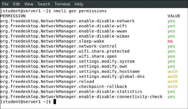
FIGURE 8-1 Verifying Current Permissions to Change Network Configuration
Configuring the Network with nmcli
Earlier in this chapter, you learned how to use ip to verify network configuration. You have also applied the ip addr add command to temporarily set an IP address on a network interface. Everything you do with the ip command, though, is nonpersistent. If you want to make your configuration persistent, use nmtui or nmcli.
A good start is to use nmcli to show all connections. This shows active and inactive connections. You can easily see the difference because inactive connections are not currently assigned to a device (see Example 8-5).
Example 8-5 Showing Current Connection Status
[root@server1 ~]# nmcli con show
NAME     UUID                                     TYPE       DEVICE
ens33    db6f53bd-654e-45dd-97ef-224514f8050a     ethernet   ens33
After finding the name of the connection, you can use nmcli con show followed by the name of the connection to see all properties of the connection. Notice that this command shows many properties. Example 8-6 shows the output of this command.
Example 8-6 Displaying Connection Properties
[root@server1 ~]# nmcli con show ens33
connection.id:                            ens33
connection.uuid:                          db6f53bd-654e-45dd-97ef-
                                            224514f8050a
connection.stable-id:                     --
connection.type:                          802-3-ethernet
connection.interface-name:                ens33
connection.autoconnect:                   yes
connection.autoconnect-priority:          0
connection.autoconnect-retries:           -1 (default)
connection.multi-connect:                 0 (default)
connection.auth-retries:                  -1
connection.timestamp:                     1558778720
connection.read-only:                     no
connection.permissions:                   --
connection.zone:                          --
connection.master:                        --
connection.slave-type:                    --
connection.autoconnect-slaves:            -1 (default)
connection.secondaries:                   --
connection.gateway-ping-timeout:          0
connection.metered:                       unknown
connection.lldp:                          default
connection.mdns:                          -1 (default)
connection.llmnr:                         -1 (default)
802-3-ethernet.port:                      --
802-3-ethernet.speed:                     0
802-3-ethernet.duplex:                    --
802-3-ethernet.auto-negotiate:            no
802-3-ethernet.mac-address:               --
802-3-ethernet.cloned-mac-address:        --
802-3-ethernet.generate-mac-address-mask: --
802-3-ethernet.mac-address-blacklist:     --
802-3-ethernet.mtu:                       auto
802-3-ethernet.s390-subchannels:          --
802-3-ethernet.s390-nettype:              --
802-3-ethernet.s390-options:              --
802-3-ethernet.wake-on-lan:               default
802-3-ethernet.wake-on-lan-password:      --
ipv4.method:                              auto
ipv4.dns:                                 --
ipv4.dns-search:                          --
ipv4.dns-options:                         ""
ipv4.dns-priority:                        0
ipv4.addresses:                           --
ipv4.gateway:                             --
ipv4.routes:                              --
ipv4.route-metric:                        -1
ipv4.route-table:                         0 (unspec)
ipv4.ignore-auto-routes:                  no
ipv4.ignore-auto-dns:                     no
ipv4.dhcp-client-id:                      --
ipv4.dhcp-timeout:                        0 (default)
ipv4.dhcp-send-hostname:                  yes
ipv4.dhcp-hostname:                       --
ipv4.dhcp-fqdn:                           --
ipv4.never-default:                       no
ipv4.may-fail:                            yes
ipv4.dad-timeout:                         -1 (default)
ipv6.method:                              auto
ipv6.dns:                                 --
ipv6.dns-search:                          --
ipv6.dns-options:                         ""
ipv6.dns-priority:                        0
ipv6.addresses:                           --
ipv6.gateway:                             --
ipv6.routes:                              --
ipv6.route-metric:                        -1
ipv6.route-table:                         0 (unspec)
ipv6.ignore-auto-routes:                  no
ipv6.ignore-auto-dns:                     no
ipv6.never-default:                       no
ipv6.may-fail:                            yes
ipv6.ip6-privacy:                         -1 (unknown)
ipv6.addr-gen-mode:                       stable-privacy
ipv6.dhcp-duid:                           --
ipv6.dhcp-send-hostname:                  yes
ipv6.dhcp-hostname:                       --
ipv6.token:                               --
proxy.method:                             none
proxy.browser-only:                       no
proxy.pac-url:                            --
proxy.pac-script:                         --
GENERAL.NAME:                             ens33
GENERAL.UUID:                             db6f53bd-654e-45dd-97ef-
                                            224514f8050a
GENERAL.DEVICES:                          ens33
GENERAL.STATE:                            activated
GENERAL.DEFAULT:                          yes
GENERAL.DEFAULT6:                         no
GENERAL.SPEC-OBJECT:                      --
GENERAL.VPN:                              no
GENERAL.DBUS-PATH:                        /org/freedesktop/
                                            NetworkManager/
                                            ActiveConnection/1
GENERAL.CON-PATH:                         /org/freedesktop/
                                            NetworkManager/Settings/1
GENERAL.ZONE:                             --
GENERAL.MASTER-PATH:                      --
IP4.ADDRESS[1]:                           192.168.4.210/24
IP4.GATEWAY:                              192.168.4.2
IP4.ROUTE[1]:                             dst = 0.0.0.0/0,
                                            nh = 192.168.4.2, mt = 100
IP4.ROUTE[2]:                             dst = 192.168.4.0/24,
                                            nh = 0.0.0.0, mt = 100
IP4.DNS[1]:                               192.168.4.2
IP4.DOMAIN[1]:                            localdomain
DHCP4.OPTION[1]:                          domain_name = localdomain
DHCP4.OPTION[2]:                          domain_name_servers =
                                            192.168.4.2
DHCP4.OPTION[3]:                          expiry = 1558780229
DHCP4.OPTION[4]:                          ip_address = 192.168.4.210
DHCP4.OPTION[5]:                          requested_broadcast_
                                            address = 1
DHCP4.OPTION[6]:                          requested_dhcp_server_
                                            identifier = 1
DHCP4.OPTION[7]:                          requested_domain_name = 1
DHCP4.OPTION[8]:                          requested_domain_name_
                                            servers = 1
DHCP4.OPTION[9]:                          requested_domain_search =1
DHCP4.OPTION[10]:                         requested_host_name = 1
DHCP4.OPTION[11]:                         requested_interface_mtu = 1
DHCP4.OPTION[12]:                         requested_ms_classless_
                                            static_routes = 1
DHCP4.OPTION[13]:                         requested_nis_domain = 1
DHCP4.OPTION[14]:                         requested_nis_servers = 1
DHCP4.OPTION[15]:                         requested_ntp_servers = 1
DHCP4.OPTION[16]:                         requested_rfc3442_classless_
                                            static_routes = 1
DHCP4.OPTION[17]:                         requested_routers = 1
DHCP4.OPTION[18]:                         requested_static_routes = 1
DHCP4.OPTION[19]:                         requested_subnet_mask = 1
DHCP4.OPTION[20]:                         requested_time_offset = 1
DHCP4.OPTION[21]:                         requested_wpad = 1
DHCP4.OPTION[22]:                         routers = 192.168.4.2
DHCP4.OPTION[23]:                         subnet_mask = 255.255.255.0
IP6.ADDRESS[1]:                           fe80::959:3b1a:9607:8928/64
IP6.GATEWAY:                              --
IP6.ROUTE[1]:                             dst = fe80::/64, nh = ::,
                                            mt = 100
IP6.ROUTE[2]:                             dst = ff00::/8, nh = ::,
                                            mt = 256, table=255
To find out what exactly these settings are doing, execute man 5 nm-settings. You can also use nmcli to show an overview of currently configured devices and the status of these devices. Type, for instance, the nmcli dev status command to show a list of all devices, and nmcli dev show <devicename> to show settings for a specific device.
Tip
Using nmcli might seem difficult. It’s not, because it offers excellent command-line completion features—just make sure that the bash-completion package has been installed. Try it by typing nmcli, but don’t press Enter! Instead, press the Tab key twice—you will see all available options that nmcli expects at this moment. Choose an option, such as connection, and press the Tab key twice. Using this approach helps you to compose long commands without the need to memorize anything!
In Exercise 8-3, you learn how to create connections and switch between connections using the nmcli command.
Exercise 8-3 Managing Network Connections with nmcli
In this exercise you create a new connection and manage its status. This connection needs to be connected to a network device. In this exercise the device ens33 is used. If necessary, change this to the name of the network device in use on your computer.
Create a new network connection by typing nmcli con add con-name dhcp type ethernet ifname ens33 ipv4.method auto.
Create a connection with the name static to define a static IP address and gateway: nmcli con add con-name static ifname ens33 autoconnect no type ethernet ip4 10.0.0.10/24 gw4 10.0.0.1 ipv4.method manual. The gateway might not exist in your configuration, but that does not matter.
Type nmcli con show to show the connections, and use nmcli con up static to activate the static connection. Switch back to the DHCP connection using nmcli con up dhcp.
In this exercise, you created network connections using nmcli con add. You can also change current connection properties by using nmcli con mod.
In Exercise 8-4, you’ll learn how to change connection parameters with nmcli.
Exercise 8-4 Changing Connection Parameters with nmcli
Make sure that the static connection does not connect automatically by using nmcli con mod static connection.autoconnect no.
Add a DNS server to the static connection by using nmcli con mod static ipv4.dns 10.0.0.10. Notice that while adding a network connection you use ip4, but while modifying parameters for an existing connection, you often use ipv4 instead. This is not a typo; it is just how it works.
To add a second item for the same parameters, use a + sign. Test this by adding a second DNS server, using nmcli con mod static +ipv4.dns 8.8.8.8.
Using nmcli con mod, you can also change parameters such as the existing IP address. Try this by using nmcli con mod static ipv4.addresses 10.0.0.100/24.
And to add a second IP address, you use the + sign again: nmcli con mod static +ipv4.addresses 10.20.30.40/16.
After changing connection properties, you need to activate them. To do that, you can use nmcli con up static.
This is all you need to know about nmcli for the RHCSA exam. As you’ve noticed, nmcli is a very rich command. The exact syntax of this command may be hard to remember. Fortunately, though, there is an excellent man page with examples. Type man nmcli-examples to show this man page; you’ll notice that if you can find this man page, you can do almost anything with nmcli. Also, don’t forget to use tab completion while working with nmcli.
Configuring the Network with nmtui
If you do not like the complicated syntax of the nmcli command line, you might like nmtui. This is a text user interface that allows you to create network connections easily. Figure 8-2 shows what the nmtui interface looks like.

FIGURE 8-2 The nmtui Interface
The nmtui interface consists of three menu options:
Edit a Connection: Use this option to create new connections or edit existing connections.
Activate a Connection: Use this to (re)activate a connection.
Set System Hostname: Use this to set the hostname of your computer.
The option to edit a connection offers almost all features that you might ever need while working on network connections. It sure allows you to do anything you need to be doing on the RHCSA exam. You can use it to add any type of connection; not just Ethernet connections, but also advanced connection types such as network bridges and teamed network drivers are supported.
When you select the option Edit a Connection, you get access to a rich interface that allows you to edit most properties of network connections. After editing the connection, you need to deactivate it and activate it again. This should work automatically, but the fact is that it does not.
Tip
If you like graphical user interface (GUI) tools, you are lucky. Use nm-connection-editor instead of nmtui, but be prepared that this interface offers a relatively restricted option set. It does not contain advanced options such as the options to create network team interfaces and manage network bridge interfaces. It does, however, offer all you need to manage address configuration on a network connection. Start it by using the nm-connection-editor command or by using the applet in the GNOME graphical interface. Figure 8-3 shows what the default interface of this tool looks like.

FIGURE 8-3 The nm-connection-editor Interface
Working on Network Configuration Files
Every connection that you create is stored as a configuration file in the directory /etc/sysconfig/network-scripts. The name of the configuration files starts with ifcfg- and is followed by the name of the network interface. In Example 8-7, you can see what such a configuration file looks like.
Example 8-7 Example of an ifcfg Configuration File
[root@server1 ~]# cat /etc/sysconfig/network-scripts/ifcfg-ens33
TYPE="Ethernet"
PROXY_METHOD="none"
BROWSER_ONLY="no"
BOOTPROTO="dhcp"
DEFROUTE="yes"
IPV4_FAILURE_FATAL="no"
IPV6INIT="yes"
IPV6_AUTOCONF="yes"
IPV6_DEFROUTE="yes"
IPV6_FAILURE_FATAL="no"
IPV6_ADDR_GEN_MODE="stable-privacy"
NAME="ens33"
UUID="db6f53bd-654e-45dd-97ef-224514f8050a"
DEVICE="ens33"
ONBOOT="yes"
If you don’t like making modifications to the network configuration with nmcli or nmtui, you can directly edit this configuration file instead. After making changes to the configuration file, use the nmcli con up command to activate the new configuration.
Tip
You can set both a fixed IP address and a dynamic IP address in one network connection. To do that, set the BOOTPROTO option in the connection configuration file to dhcp, while you also specify an IP address and network prefix. You can do this also from the nmtui utility; just make sure that in nmtui the IPv4 configuration is set to automatic (and not to manual) and specify an IP address as well. I recommend that you do this in the test configuration you are using with this book, because it allows you to use a static network address configuration for internal use, in addition to a dynamic configuration that allows you to access the Internet and install software from repositories.
Setting Up Hostname and Name Resolution
To communicate with other hosts, hostnames are used. As an administrator, it is important that you know how to set the hostname. You also need to make sure that hosts can contact one another based on hostnames by setting up hostname resolution. In this section, you learn how to do that.
Hostnames
Because hostnames are used to access servers and the services they’re offering, it is important to know how to set the system hostname. A hostname typically consists of different parts. These are the name of the host and the DNS domain in which the host resides. These two parts together make up for the fully qualified domain name (FQDN), which looks like server1.example.com. It is good practice to always specify an FQDN, and not just the hostname, because the FQDN provides a unique identity on the Internet. There are different ways to change the hostname:
Use nmtui and select the option Change Hostname.
Use hostnamectl set-hostname.
Edit the contents of the configuration file /etc/hostname.
To configure the hostname with hostnamectl, you can use a command like hostnamectl set-hostname myhost.example.com. After setting the hostname, you can use hostnamectl status to show the current hostname. Example 8-8 shows the output of this command.
Example 8-8 Showing Current Hostname Configuration
[root@server1 ~]# hostnamectl status
    Static hostname: server1.example.com
         Icon name : computer-vm
           Chassis : vm
        Machine ID : 5aa095b495ed458d934c54a88078c165
           Boot ID : 5fdef4be9cab48c59873af505d778761
    Virtualization : vmware
  Operating System : Red Hat Enterprise Linux 8.0 (Ootpa)
       CPE OS Name : cpe:/o:redhat:enterprise_linux:8.0:GA
           Kernel  : Linux 4.18.0-80.el8.x86_64
      Architecture : x86-64
When using hostnamectl status, you see not only information about the hostname but also information about the Linux kernel, virtualization type, and much more.
Alternatively, you can set the hostname using the nmtui interface. Figure 8-4 shows the screen from which this can be done.
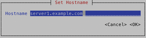
FIGURE 8-4 Changing the Hostname Using nmtui
To set hostname resolution, DNS is typically used. Configuring a DNS server is not an RHCSA objective, but you need to know how to configure your server to use an existing DNS server for hostname resolution. Apart from DNS, you can configure hostname resolution in the /etc/hosts file. Example 8-9 shows the contents of an /etc/hosts file.
Example 8-9 /etc/hosts Sample Contents
[root@server1 ~]# cat /etc/hosts
127.0.0.1    localhost localhost.localdomain localhost4 localhost4.
  localdomain4
::1          localhost localhost.localdomain localhost6 localhost6.
  localdomain6
All hostname–IP address definitions as set in /etc/hosts will be applied before the hostname in DNS is used. This is configured as a default in the hosts line in /etc/nsswitch.conf, which by default looks like this:
hosts: files dns myhostname
Setting up an /etc/hosts file is easy; just make sure that it contains at least two columns. The first column has the IP address of the specific host, and the second column specifies the hostname. The hostname can be provided as a short name (like server1) or as an FQDN. In an FQDN, the hostname as well as the complete DNS name are included, as in server1.example.com.
If a host has more than one name, like a short name and a fully qualified DNS name, you can specify both of them in /etc/hosts. In that case, the second column must contain the FQDN, and the third column can contain the alias. Example 8-10 shows a hostname configuration example.
Example 8-10 /etc/hosts Configuration Example
[root@server2 ~]# cat /etc/hosts
127.0.0.1    localhost localhost.localdomain localhost4 localhost4.
  localdomain4
::1          localhost localhost.localdomain localhost6 localhost6.
  localdomain6
10.0.0.10     server1.example.com server1
10.0.0.20     server2.example.com server2
DNS Name Resolution
Just using an /etc/hosts file is not enough for name resolution if you want to be able to communicate with other hosts on the Internet. You should use DNS, too. To specify which DNS server should be used, set the DNS server using nmcli or nmtui as previously discussed. The NetworkManager configuration stores the DNS information in the configuration file for the network connection, which is in /etc/sysconfig/network-scripts, and from there pushes the configuration to the /etc/resolv.conf file, which is used for DNS name server resolving. Do not edit /etc/resolv.conf directly, as it will be overwritten the next time you restart NetworkManager.
It is recommended to always set up at least two DNS name servers to be contacted. If the first name server does not answer, the second name server is contacted. To specify which DNS name servers you want to use, you have a few different options:
Use nmtui to set the DNS name servers. Figure 8-5 shows the interface from which you can do this.
Set the DNS1 and DNS2 parameters in the ifcfg network connection configuration file in /etc/sysconfig/network-scripts.
Use a DHCP server that is configured to hand out the address of the DNS name server.
Use nmcli con mod <connection-id> [+]ipv4.dns <ip-of-dns>.

FIGURE 8-5 Setting DNS Servers from the nmtui Interface
Notice that if your computer is configured to get the network configuration from a DHCP server, the DNS server is also set via the DHCP server. If you do not want this to happen, you have two options:
Edit the ifcfg configuration file to include the option PEERDNS=no.
Use nmcli con mod <con-name> ipv4.ignore-auto-dns yes.
To verify hostname resolution, you can use the getent hosts <servername> command. This command searches in both /etc/hosts and DNS to resolve the hostname that has been specified.
Exam Tip
Do not specify the DNS servers directly in /etc/resolv.conf. They will be overwritten by NetworkManager when it is (re)started.
Summary
In this chapter, you learned how to configure networking in RHEL 8. First you read how the IP protocol is used to connect computers, and then you read which techniques are used to make services between hosts accessible. Next you read how to verify the network configuration using the ip utility and some related utilities. In the last part of this chapter, you read how to set IP addresses and other host configuration in a permanent way by using either the nmcli or the nmtui utility.
Exam Preparation Tasks
As mentioned in the section “How to Use This Book” in the Introduction, you have several choices for exam preparation: the end-of-chapter labs; the memory tables in Appendix B; Chapter 26, “Final Preparation”; and the practice exams.
Review All Key Topics
Review the most important topics in the chapter, noted with the Key Topic icon in the outer margin of the page. Table 8-3 lists a reference of these key topics and the page number on which each is found.
Table 8-3 Key Topics for Chapter 8
Key Topic Element |
Description |
Page |
|---|---|---|
List |
IPv4 and IPv6 short descriptions |
|
List |
Private network addresses |
|
Binary-decimal conversion overview |
||
List |
IP address types |
Complete Tables and Lists from Memory
Print a copy of Appendix B, “Memory Tables” (found on the companion website), or at least the section for this chapter, and complete the tables and lists from memory. Appendix C, “Memory Tables Answer Key,” includes completed tables and lists to check your work.
Define Key Terms
Define the following key terms from this chapter and check your answers in the glossary:
Review Questions
The questions that follow are meant to help you test your knowledge of concepts and terminology and the breadth of your knowledge. You can find the answers to these questions in Appendix A.
1. What is the network address in the address 213.214.215.99/29?
2. Which command only shows link status and not the IP address?
3. Which service manages network configuration in RHEL 8?
4. Which file contains the hostname in RHEL 8?
5. Which command enables you to set the hostname in an easy way?
6. Which command do you need to run after manually changing the contents of the /etc/sysconfig/ifcfg files?
7. Which configuration file can you change to enable hostname resolution for a specific IP address?
8. Which command shows the current routing configuration?
9. How do you verify the current status of the NetworkManager service?
10. Which command enables you to change the current IP address and default gateway on your network connection?
End-of-Chapter Lab
For exercises in later chapters in this book, it is recommended to have a test environment in which at least two servers are present. To do the exercises in this lab, make sure that you have a second server installed.
Lab 8.1
1. Set up the first server to use the FQDN server1.example.com. Set up the second server to use server2.example.com.
2. On server1.example.com, use nmtui and configure your primary network card to automatically get an IP address through DHCP. Also set a fixed IP address to 192.168.4.210. On server2, set the fixed IP address to 192.168.4.220.
3. Make sure that from server1 you can ping server2, and vice versa.
4. To allow you to access servers on the Internet, make sure that your local DHCP server provides the default router and DNS servers.