
4.6. RELIABILITY OF A ROD UNDER AXIAL LOADING 191
A
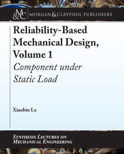
Thickness: t = 0.375 ± 0.005˝
L
1
= 10.000 ± 0.005˝
h
1
= 1 ± 0.003˝
L
2
= 7.000 ± 0.003˝
h
2
= 0.500 ± 0.003˝
B
F
C
Figure 4.8: A stepped plate under an axial loading.
allowable deformation of the entire stepped plate is less than 0:008
00
. Use the Monte Carlo
method with a 95% confidence level to calculate the reliability of the stepped plate.
Solution:
1. Axial loading and geometric parameters in each segment.
is stepped-plate can be divided into two segments. e loading and corresponding ge-
ometric parameters for each segment are listed in Table 4.24.
Table 4.24: e loading and corresponding geometric parameters for each segment
Segment AB Segment BC
Length Cross-section area Axial loading Length Cross-section area Axial loading
L
1
h
1
t F L
2
h
2
t
F
e deformation of the entire plate per Equation (4.19) will be:
ı D
FL
1
Eh
1
t
C
FL
2
Eh
2
t
D
F .L
1
h
2
C L
2
h
1
/
Eh
1
h
2
t
: (a)
2. e limit state function of the stepped plate for the deformation issue.
e limit state function of this example can be established per Equation (4.20):
g
.
E; L
1
; L
2
; h
1
; h
2
; t
/
D 0:008
F
.
L
1
h
2
C L
2
h
1
/
Eh
1
h
2
t
D
8
ˆ
<
ˆ
:
> 0 Safe
0 Limit state
< 0 Failure:
(b)

192 4. RELIABILITY OF A COMPONENT UNDER STATIC LOAD
In this example, the axial loading F is a discrete random variable and described by a PMF.
e limit state function of the stepped plate can be expressed as the following three dif-
ferent limit state functions.
When F D F
1
D 3150 (lb), the limit state function of the stepped plate is:
g
.
E; L
1
; L
2
; h
1
; h
2
; t
/
D 0:008
3150
.
L
1
h
2
C L
2
h
1
/
Eh
1
h
2
t
D
8
ˆ
<
ˆ
:
> 0 Safe
0 Limit state
< 0 Failure:
(c)
When F
a
D F
2
D 3200 (lb), the limit state function of the stepped plate is:
g
.
E; L
1
; L
2
; h
1
; h
2
; t
/
D 0:008
3200
.
L
1
h
2
C L
2
h
1
/
Eh
1
h
2
t
D
8
ˆ
<
ˆ
:
> 0 Safe
0 Limit state
< 0 Failure:
(d)
When F
a
D F
3
D 3250 (lb), the limit state function of the stepped plate is:
g
.
E; L
1
; L
2
; h
1
; h
2
; t
/
D 0:008
3250
.
L
1
h
2
C L
2
h
1
/
Eh
1
h
2
t
D
8
ˆ
<
ˆ
:
> 0 Safe
0 Limit state
< 0 Failure:
(e)
Per Equation (4.16), the reliability of the plate in this example will be:
R D p
1
R
1
C p
2
R
2
C p
3
R
3
; (f )
where p
1
, p
2
, and p
3
are the PMF for the axial loading F
a
when it is equal to F
1
D
3150 (lb), F
2
D 3200 (lb), and F
3
D 3250 (lb), respectively. R
1
is the reliability of the
stepped plate determined by the limit state function (c). R
2
is the reliability of the stepped
plate determined by the limit state function (d). R
3
is the reliability of the stepped plate
determined by the limit state function (e).
e geometric dimensions and the loading can be treated as normal distributions. For
geometric dimensions L
1
; L
2
; h
1
; h
2
, and t , we can use Equation (4.1) to calculate their
means and standard deviations. All distribution parameters of random variables in the
limit state function Equations (c), (d), and (e) are displayed in Table 4.25.
3. e reliability of the stepped plate.
We will use the Monte Carlo simulation method to calculate the reliability R
1
, R
2
,
and R
3
of this example. en, we can use Equation (f) to calculate the reliability of the
stepped plate. Since the stepped bar is a key component, we will use the trial number
N D 1,598,400 from Table 3.2 in Section 3.8. We can follow the Monte Carlo method
..................Content has been hidden....................
You can't read the all page of ebook, please click here login for view all page.