Technical Challenges to xDSL
As discussed earlier in the section "Benefits and Business Rationale of DLC," telcos have a number of compelling business reasons to pursue xDSL. The benefit to the customer is faster service than POTS or ISDN. But although the general architecture of DSL service for POTS and ISDN is well known, using the same infrastructure for high-speed services presents new technical problems.
Loop Qualification
The ideal local loop has no loading coils , no changes in wire gauge, and no bridged taps; is well insulated; and is as short as possible. Reality is different. End-to-end performance of the local loop is impacted by loop length, loading coils, quality of end-to-end splicing of wiring segments, multiple changes of wire gauge, home wiring, age, corrosion, hostile binder groups, crosstalk, and bridged taps. Furthermore, most local loops are unnecessarily long as they snake around physical obstructions both indoors and outdoors.
Exactly how many of the United States' 167 million lines or the world's 650 million lines are qualified to support ADSL? According to a study by Bell South, only 41 percent of the 12.6 million loops in their region qualify for ADSL. (See www.interconnection.bellsouth.com/products/pdf_coll/adsl_dep.pdf. ). CLECs would dispute this figure, arguing it is much higher and claiming that ILECs are low-balling the figure so that they would not be required to unbundle the loops. Telcos today are busy determining the answer using sampling, measurements, and experience gained from the rollout of ISDN and VoD trials.
Crosstalk
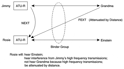
Crosstalk, specifically near-end crosstalk (NEXT), is interference that occurs among wires wrapped in a single binder group. Each wire is unshielded; therefore, one wire pair can interfere with another through electromagnetic coupling. In Figure 4-9, Jimmy and Rosie are communicating with Grandma and Einstein, respectively. An example of crosstalk is when Rosie receives transmission from two sources. She hears intended traffic from Einstein and spurious traffic from Jimmy. She will not hear spurious traffic from Grandma because the distance will attenuate Grandma's signal. Hence, the problem is near-end crosstalk rather than far-end crosstalk (FEXT).
Figure 4-9. Crosstalk Visualized

Crosstalk increases rapidly as a function of frequency. Because voice is a relatively low-frequency service, crosstalk is not a problem. But AMI-encoded T1 wires create a special problem because of the high frequencies used by AMI.
AMI requires repeaters 3000 feet from the central office and every 6000 feet thereafter, and consumes more 1.0 MHz of bandwidth. Hundreds of thousands of lines (T1 and E1) exist in the world today. But AMI encoding uses so much bandwidth and creates so much crosstalk that telephone companies cannot put more than one AMI-encoded line in a single 50-pair cable.
Because AMI encoded T1 can use up to 1 MHz of bandwidth, it cannot coexist in the same binder group with ADSL. Identifying which binder groups contain such T1 lines requires accurate record keeping, which has not always been maintained. Some carriers plan to restrict the copper plant that ADSL will use, keeping it separate from transmission technologies that could cause crosstalk.
However, ADSL is intended to coexist with more modern services. In particular, ADSL is specified to operate with multiple ISDN and T1 HDSL services in the same binder over a CSA loop (9000 feet on 26 AWG) at 6 Mbps. It will not interoperate with T1 encoded with AMI—but then, nothing will coexist with AMI.
ADSL uses frequencies up to 1 MHz. VDSL can go up to 10 MHz and can create a massive amount of crosstalk. Because the phone wires and binder groups to be used by VDSL were never specified for such high-frequency operation, crosstalk will be much higher than contemplated for modern cables.
Early deployment will not pose much of a problem because of the few number of users, owing to VDSL's short distance. But, as the network includes more and more VDSL systems, and as crosstalk from other VDSL systems grows, the operator might have to replace some binder groups, resulting in a loss of service to the user as well as incremental installation costs.
One of the criticisms leveled at HFC is that shared media creates a loss of QoS. In a sense, however, the same occurs for point-to-point service such as DSL. A binder group can be considered a shared media because wires in a binder group are not shielded from one another; users can affect other users.
Bridged Taps
Bridged taps are a legacy of phone wiring installation practices, where a pair coming from a CO is branched into a Y form. The idea is to be able to use either branch of the Y to provision new subscribers. This layout has no affect at the low frequencies used by POTS, but it can be a significant impairment for DSL services. That's because the bridged taps are sources of echo. Signals from the CO hit the branching point and go along both branches of the Y. They can then bounce back to the other branch. Sometimes one of the branches is not terminated, which creates signal loss. Echo cancellation works very well when an echo has only one source, but when the original signal bounces off several places, cancellation becomes less effective.
Powering Remote Terminals
DSLAMs and ATU-Cs could possibly be located in controlled vaults and pedestals to increase neighborhood penetration and total available market. For VDSL, it might be necessary to locate equipment on telephone poles to justify a business case. These facilities have limited space; are out in the open; are subject to vandalism, water damage, and other environmental problems; and require powering. One big problem is heat dissipation. xDSL services need to minimize power consumption so that a smaller amount of heat is dissipated. For the moment, CAP has a 3- to 4-watt advantage over DMT in terms of power consumption. Local power will likely be used to power DSL equipment, but battery backup is needed for emergencies. This also puts a premium on low-powered solutions.
Spectral Masking
ADSL is subject to multiple forms of long-term narrowband interference such as crosstalk. AM radio and amateur radio ingress are potential interferors, both of which can operate below 1 MHz. One way to avoid stationary narrowband interference is to mask out the offending frequencies and to avoid using them for ADSL transmission.
Such masking can be accomplished with notch filters, typically passive devices that notch out certain frequencies permanently. If the source of narrowband interference comes and goes, however, then passive filters might be insufficient. Active filters can handle such dynamic interference but are more costly.
The term spectral masking refers to the process of notching out specific frequencies. In this environment, DMT operates rather naturally. Those frequencies that are notched out correspond to a certain subband and are not used by DMT. Because CAP modulates the entire spectrum, some adaptive equalization tricks are necessary to make it work with spectral masking.
Impulse Noise
Impulse noise on phone wire has been characterized by Bellcore and, before that, AT&T Bell Labs, so it is fairly well understood. Impulse noise is short-term interference affecting many frequencies, the duration of which is on the order of 100 microseconds, with peak power around 10 millivolts. The solution is to use interleaving and Reed-Solomon forward-error correction. Current thinking is to use RS (200,216) coding for the interleaved (slow) channel.
Impulse noise is the phenomenon that precipitated the discussion on dual latency for ADSL and its complications for networking. One important source of impulse noise is ringer noise from adjacent pairs.
ATU-R Maintenance
The ATU-R is more intelligent than the conventional POTS modem. For example, the ATU-R is capable of making software revisions, such as algorithms, for line calibration changes or if the carrier decides to change encapsulation protocols. Discussions are ongoing as to how software maintenance for the ATU-R is to be accomplished. Resistance is present to the carrier remotely managing it, in part because this is not the model used for current POTS or ISDN service. As in the case of cable modems, ATU-R maintenance raises new problems, such as software updating, and can have serious cost consequences.
