
![]()
Solderless Breadboard Setup
In this chapter, you’ll prepare an 840 tie-point solderless breadboard for experimentation (see Figure 13-1). You’ll install a battery, power switch, and an LED power indicator. You can use this basic setup over and over again for trying out robot circuits and modules.

Figure 13-1. Solderless breadboard after completed setup
Considering Power Sources
There are a lot of good options available for supplying power to a circuit on a breadboard.
Continuous power is available by attaching the circuit to a wall outlet through an ordinary power adaptor (otherwise known as a wall wart). Replacement adjustable-voltage supplies are available at most consumer electronics retailers and some hardware stores. Or, you can salvage a fixed-voltage supply from a consumer device, such as an answering machine or old cable modem. I choose to power circuits from an outlet if they consume a lot of current or are going to be hooked up for long periods.
However, most of the time, I choose 9 V rechargeable batteries. They’re portable, safe (low power, low maximum current), small, and I don’t have to drape power supply cables across my desk. A 9 V battery provides plenty of power for most digital circuits. It’s beneficial to test circuits on a breadboard using the same power source that they will experience on the robot.
Obtaining 9 V Battery Snap Connectors
Although you could attach the battery to the breadboard using alligator or hook clip jumpers, a 9 V battery snap connector is preferable because it’s less likely to slip off. I highly recommend a solid, rigid 9 V connector rather than an ordinary, flexible connector (see Figure 13-2). The flimsy connectors are difficult to remove from the battery and tend to wear out quickly, often ripping or falling apart. See Table 13-1 for a supplier of rigid clips.
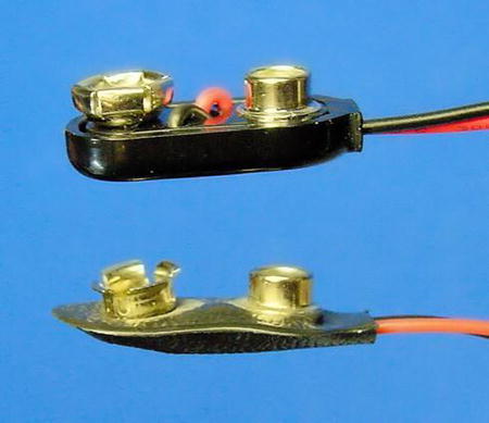
Figure 13-2. Solid (top) versus flimsy (bottom) 9 V battery snap connectors
Table 13-1. Solid, Rigid 9 V Battery Snap Connectors

Connecting Power to Binding Posts
You could push the ends of the 9 V snap connector’s wires directly into the desired breadboard holes. However, the battery often falls when the breadboard is moved, causing one or both 9 V wires to pull out of their respective holes.
A better solution is to connect the 9 V wires to the binding posts (if available on your breadboard). Obviously, the black wire connects to the black post, and the red wire connects to the red post. Any red post will do if you have more than one.
Because only a short amount of the plastic insulation is already stripped off of the end of the snap connector’s wires, strip off a little bit more. Then insert the bare ends into the binding post holes (see Figure 13-3).

Figure 13-3. Inserting the 9 V snap connector’s wire (stripped) into a breadboard post
Make a short length of red and black #22 American wire gauge (AWG) copper wire and insert them into their respective post holes. You should wrap the wire ends around the metal portion of the post to achieve a reliable connection. Place the short lengths of #22 wire into the desired holes of the breadboard. (Skip ahead to Figure 13-8 for a photograph of the battery and post connections as viewed from a different angle.)
Electricity will flow from the battery terminal, through the snap connector wire, to the post, to the #22 wire, and finally to the breadboard hole.
An advantage of attaching the power source to the binding posts is that you can conveniently connect a multimeter to the banana jacks atop the posts to check voltage. Also, you can disconnect the 9 V battery from the snaps and connect a wall adaptor to the binding posts.
![]() Caution Never connect a battery and a wall power source to the same circuit at the same time. If you still want to leave the batteries connected to the circuit, rechargeable and non-rechargeable batteries will require specifically designed protection to avoid destruction when the wall power is applied.
Caution Never connect a battery and a wall power source to the same circuit at the same time. If you still want to leave the batteries connected to the circuit, rechargeable and non-rechargeable batteries will require specifically designed protection to avoid destruction when the wall power is applied.
Choosing a Power Switch
How suave is it to lunge after your out-of-control robot and rip out the batteries? Polished robot designs have power switches. Easily accessible power switches are vital during prototyping, as the circuits may suffer a few shorts and power overloads during development.
Unfortunately, few switch sizes are compatible with breadboards. Either the switch leads are too thick or they are spaced apart at a distance other than 0.1 inch. As such, you can’t push the switch into the breadboard holes. Bending or trimming the power-switch leads is rarely successful, as the switch needs to be firmly in place or else it falls out when you physically try to use it.
I’m aware of a couple of switches with solderless breadboard dimensions (see Figure 13-4). They’re so indispensable that you should have a dozen on hand. The EG1218 switch is more compact, which can be advantageous as your robot’s circuit board runs out of space. The 600SP1S2 switch is a little easier to toggle because of its larger size. Table 13-2 lists suppliers of breadboard-compatible switches.
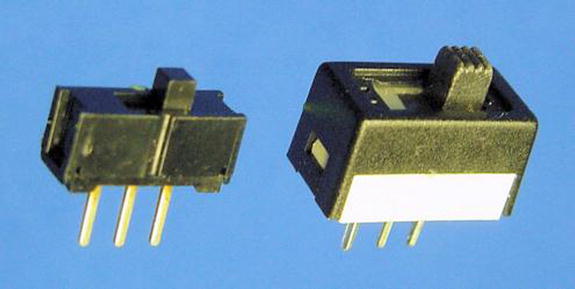
Figure 13-4. Breadboard-compatible switches: EG1218 (left) and 600SP1S2 (right)
Table 13-2. Breadboard-Compatible SPDT Slide Switches

Understanding SPDT
Slide switches are activated by sliding the actuator back and forth. The term SPDT stands for single pole, double throw.
Think of SPDT like a tall metal pole standing in the middle, separated from wires on the left and on the right. When the actuator is slid to the left, the metal pole is thrown onto the left wire, connecting the pole and left wire. When the actuator is slid to the right, the metal pole is thrown onto the right wire, connecting the pole and right wire.
Other than for a brief second, the metal pole is not standing completely disconnected in the middle. It either slams down on the left side or slams down on the right side. At no time do the left and right wires touch each other. Nor can the pole touch both the left and right wires at the same time.
Adding a Power Switch to the Breadboard
You want to connect the negative (black) wire directly to the breadboard’s power distribution bus. However, you want the positive (red) wire to go through the switch so that you can easily disconnect it, stopping the flow of electricity.
Up to this point, you have negative battery power connected to the black binding post with a #22 black wire coming out. Insert the black wire to the rightmost hole on the second row from the top (see Figure 13-5). This row is a distribution bus, so now negative power is available to the many holes in that row.

Figure 13-5. Placing a switch into solderless breadboard holes (viewed from above the upper-right of the board)
Positive battery power is connected to the red binding post with a #22 red wire coming out. Instead of connecting the red wire directly to the first row at the top, connect it to a 5-position group just below the distribution bus (again, see Figure 13-5). This way you can have the switch connect and disconnect positive power from the remainder of the circuit.
Place a SPDT power switch so that the middle lead is in the same 5-position group as the positive power wire (also Figure 13-5). The placement of the middle lead of the switch and the positive wire creates a connection between them.
Connecting Power Buses
Use a small red jumper wire to connect the left lead of the switch to the uppermost row on the breadboard (see Figure 13-6). Positive power and negative power are now connected to the upper two rows, but positive power first passes through the switch.

Figure 13-6. Adding a wire to connect the top row to positive power through the switch
When the switch actuator is slid left, positive power is connected. When the switch actuator is slid right, positive power is disconnected. It doesn’t matter that negative power is connected the whole time.
Adapting Multimeter Probes Using Jumper Wire
Because of their thickness, it’s not possible for bare multimeter probe tips or hook adaptors to reach the metal strips beneath the breadboard holes. Using a hook adaptor, connect a piece of ordinary copper wire or a reinforced jumper wire to the multimeter probe tip (see Figure 13-7). Now you can check the voltage in any group or hole by inserting the wire.

Figure 13-7. Multimeter probes with hook adaptors holding a reinforced jumper wire
To determine if the top rows are properly connected to the battery’s power, use a wire on each multimeter probe to check the voltage of the top two rows (see Figure 13-8). Flip the switch back and forth to see that the voltage changes from zero to full (approximately 9 V).

Figure 13-8. Testing the voltage of the upper bus using probes hooked to jumper wire
Connecting the Lower Bus
Connect the top row of the upper bus to the top row of the lower bus with red jumper wire (see Figure 13-9). Connect the bottom row of the upper bus to the bottom row of the lower bus with black jumper wire. Now battery power is available uptown and downtown!

Figure 13-9. Jumper wires delivering power to lower bus rows
Split Down the Middle
The buses on an 840 tie-point breadboard don’t extend all of the way across the board; they’re split halfway. Use jumper wire on the top two rows and bottom two rows in the middle of the breadboard (see Figure 13-10).

Figure 13-10. Jumper wires connecting the left side to the right side of the breadboard
With the voltage feature of a multimeter, check that battery power is now distributed in the upper and lower rows (distribution busses) all across the breadboard.
Installing a Power Indicator LED
Recall the LED power indicator circuit you built earlier with alligator-clip jumper leads. Basically, it consisted of a resistor hooked to positive power and then to an LED. The other end of the LED was connected to negative power. The LED turned off whenever the battery was disconnected at any point in the loop.
Since you’ve distributed power throughout the board, you can add the power indicator circuit wherever you’d like. I chose the lower-right corner because there’s just enough space there.
Insert one lead of a 1 kΩ resistor into any hole that has positive power. Insert the other resistor lead into a 5-position group (see Figure 13-11).

Figure 13-11. LED power indicator circuit connected to lower bus
In that same 5-position group, insert the anode of a red LED. Note that the LED isn’t receiving the full force of the battery because power is supplied to the group only through the protective (current limiting) resistor.
Insert the cathode of the red LED into an adjacent 5-position group. Connect the adjacent group to any hole that has negative power by using a black jumper wire.
The red LED should light when the power switch is turned on. The LED should extinguish when the power switch is turned off.
Checking Voltages at Certain Points
You should check the voltages of the breadboard power indicator circuit to be assured they are similar to the same circuit assembled with alligator-clip jumper leads.
Recall that to test voltage at a point, the black multimeter test probe must be connected to negative power. Since you’ve connected the battery’s negative terminal to the black binding post and to the bottom row of both upper and lower buses, you can connect the black test probe to any of those locations.
In Figure 13-12, I chose to connect the black test probe to the bottom row of the lower bus. I could have chosen any hole on the bottom row of the board because they are all connected to negative power.

Figure 13-12. Multimeter probes with jumpers testing voltage at the LED’s anode
This is why distribution buses are so valuable. You can add individual modules and mini circuits anywhere on the board and it will be as if they all were connected directly to the battery. Of course, the 5-position groups aren’t connected to the buses, so you can deliver the desired voltage and current to them based on your choice of resistor or other part.
With the black test probe connected to negative power, insert a wire connected to the red test probe into the 5-position group that contains the LED anode (see Figure 13-12). You should get a reading of 1.8 V (or thereabouts), just as you did when the power indicator circuit was put together with alligator-clip jumper leads.
Trimming Leads
After testing a part or circuit on a breadboard, you may want to cut down the part’s leads. Short, flush parts stay out of your way and there isn’t the risk of their leads accidentally brushing against other wires.
The LED and resistor of the breadboard power indicator are good candidates for trimming down. Chances are you’ll leave those parts in the breadboard for almost all experiments.
Demystifying the Robot’s Power Switch
The power switches on most robots are no different than the power switch you installed on your breadboard. Robot power switches may look more striking, handle more voltage, or make multiple connections at the same time. However, robot power switches still employ the same technique of making and breaking a connection to the positive terminal of the power source.
In fact, nearly all robots deliver power to their circuits and modules using a power bus, just like a solderless breadboard. Figure 13-13 is a photograph of the underside of Sandwich’s circuit board. It has an array of holes, just like a solderless breadboard. Toward the middle, there are two long lines that all the various circuits are tapping into. Those are the positive and negative buses.

Figure 13-13. Sandwich’s circuit board with power buses
The negative terminal of the 9 V battery is always connected to the negative bus on Sandwich’s circuit board. The power switch has one end connected to the positive terminal of the 9 V battery and the other end to the positive bus. All of this is just like on your solderless breadboard.
When you flip the robot’s power switch on, the power flows from the positive terminal of the battery through the switch to the positive bus, through the various circuits, into the negative bus, which leads back to the negative terminal of the battery.
I admit that Sandwich’s board is pretty messy. Also, some of the parts, like the switches, have been stretched off the board via wires. But the only significant difference between Sandwich’s breadboard and a solderless breadboard is that Sandwich’s parts are soldered together rather than pushed into little group holes.
Ready for More
Your solderless breadboard has been prepared. It’s ready to supply power to its wide-open spaces with a flick of a switch. You know how to test voltage at any point to make sure the values are in the ranges that the parts can accept.
Are you ready to learn about some new parts, such as sensors, and add them to your breadboard?