
![]()
Soldering and Connecting
This chapter covers soldering, with emphasis on soldering smaller pieces, like the motors and the line-following switch. This chapter also describes instances when it’s better to not solder certain wires together, but instead to use a connector.
Putting Together the Motors and Switches
Before attempting to solder the line-following circuit (next chapter), it’s prudent to practice on less complicated parts. For example, each motor only needs two wires soldered to it.
The switches, motors, and a few other items (see Figure 22-1) are all independent from each other and from the main circuit board. That makes them short and easy projects to work on.

Figure 22-1. (left to right) Motors, line-following switch, battery snap, power switch, and tube LEDs. They’re all soldered to Molex KK connectors and insulated with heat-shrink tubing
You’ll begin by soldering wires to each component and then protecting the component terminals with heat-shrink tubing. After that you’ll attach connectors to the ends of the wires and twist the wires around themselves. If you don’t quite understand the instructions that follow, refer to Figure 22-1 to remind yourself of the final result.
Putting Together the Motors
The following steps describe how to attach wires and connectors to the DC gearhead motors. When complete, you can quickly attach and remove the individual motors from the line-following circuit.
Preparing and Attaching the Motor Wires
Solid wire was selected for the solderless breadboard because it doesn’t fray on the ends when being inserted into the breadboard holes. However, stranded wire is a better choice for a soldered circuit because stranded wire is more flexible and it readily twists around the joint to be soldered.
- Obtain some white and some black stranded #22 AWG wire to be soldered to the positive and negative motor terminals, respectively.
- Cut two pieces of white wire and two pieces of black wire to about 15 cm in length each (four 15 cm pieces total).
- Using wire strippers, remove about 1.5 cm of plastic insulation from one end of each wire, and about 0.35 cm of insulation from the other end of each wire (see Figure 22-2).

Figure 22-2. Two white and two black wires cut to the correct length with their ends stripped
- Loop the 1.5 cm stripped end of a white wire through the eyelet (hole) in the positive terminal of a motor (see the left side of Figure 22-3).

Figure 22-3. Stranded wire looped through the eyelet in the positive motor terminal (left). Wire twisted around itself to hold firmly and provide multiple points of electrical connection to motor terminal (right)
- Twist the wire around itself to provide a firm grip on the terminal (see the right side of Figure 22-3). Serrated needle-nose pliers work well for this task.
Here is the first rule of soldering: Whenever possible, the pieces to be joined should hold themselves together and have as much contact with each other as possible.
The solder should be a bonus. Don’t try to connect pieces that aren’t touching by creating a solder bridge. Don’t rely solely on the holding strength of solder to connect pieces that will undergo mechanical strain.
- Attach the black wire to the negative motor terminal in the same manner.
Although it might seem that these connections are firm enough as is, these connections would eventually loosen and pull apart during use unless soldered.
Holding the Motor Firmly and Preparing the Soldering Iron
- Place the motor in a helping hand (see Figure 22-4) or vise, so that it doesn’t move during soldering.
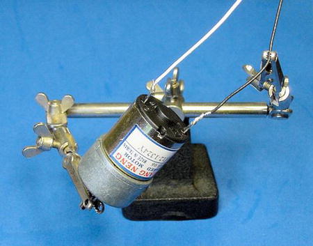
Figure 22-4. Helping hands holding motor and wire in preparation for soldering
- Follow the steps listed in the previous chapter for preparing the sponge, heating up the iron, cleaning the tip, and tinning.
Soldering the Motors
- Touch the soldering iron tip to one side of the motor terminal and wire, directly at the point of connection (see Figure 22-5). It is important to make as much contact with the clean, tinned tip so that heat transfers to the wire and motor terminal.

Figure 22-5. Soldering iron tip on one side of the wire, solder on the other side of the wire
- Press the solder wire against the other side of the motor terminal and wire.
Here is the second rule of soldering: the solder to be applied should be touched against the heated joint, not the soldering iron tip.
Because the solder wire is heated by the joint instead of the soldering iron tip, the solder-wire flux core cleans the heated metal and then the molten solder flows over, into, and around the joint.
Sometimes, I’ll briefly place the solder wire at the location where the soldering iron tip meets the joint, so that a small amount of molten solder provides a high-quality thermal path between the soldering iron tip and the joint. Then I’ll switch the solder wire to the other side to insure that the joint has been heated up enough and that the molten solder flows throughout the entire joint.
Beginners often try to apply solder to the soldering iron tip and then brush the molten solder against the joint. Although this appears to work, the solder wire’s flux core cleans only the soldering iron tip and burns off before reaching the joint. Also, the solder coats only the surface of the joint; it doesn’t flow into all the nooks and crannies.
With a properly cleaned and heated tip, the solder wire should melt from the other side of the small joint in three seconds or less. If it isn’t melting, pull back and let the area cool. On the next attempt, make sure the tip is clean and is making firm contact against the joint. A bit of molten solder between the tip and the joint may help.
Thicker leads and larger metal pieces take longer to heat up. This is because the heat is absorbed by the metal and conducted away before the solder can melt. In these situations, slide the solder wire nearer the soldering iron tip and the joint. Be a little more patient, it may take up to five seconds for the solder to flow on larger or thicker metal.
- After the solder first starts to flow, it should only take a second or two more to completely flow around and through the entire joint. Now you can remove the solder wire from the joint.
- After you have removed the solder wire, you can then remove the soldering iron tip from the joint. If you remove the soldering iron tip before the solder wire, the solder wire cools and sticks to the joint or deforms the solder joint’s shape as the solder wire is pulled off.
- You should be pleasantly rewarded with a shiny, strong, rounded, encompassing solder joint (see Figure 22-6).

Figure 22-6. Wire and terminal soldered together
If you aren’t happy with the shape or shine of the joint, simply reheat it with the soldering iron tip and let the joint cool again. Additional solder is not necessary, just the soldering iron tip. This usually corrects mistakes and allows the molten solder to reflow thoroughly.
If you’ve applied too little solder, reheat the joint and apply additional solder wire. If you’ve applied too much solder, reheat the joint and use the desoldering bulb to remove excess. Occasionally it’s cleaner to remove almost all of the solder at the joint and then apply the desired amount of fresh solder from the solder wire.
- Repeat these steps to solder the black wire to the negative terminal.
- Repeat these steps to solder the white and black wires to the other motor.
- Test that the wires are attached correctly by connecting them briefly to a 9 V battery. The motor should spin.
In Soldering, Practice Makes Perfect
How did the soldering turn out? If it didn’t turn out as well as you hoped, don’t despair. Good soldering takes practice.
One of my first soldering experiences was to construct a 32-byte read-only memory panel out of 256 diodes (see Figure 22-7). It took 816 solder joints to complete. During testing I discovered half a dozen disconnected or intermittent solder joints. After carefully reheating each one (and a few I didn’t trust), the board worked like a charm.

Figure 22-7. Array of 256 diodes requiring 816 solder connections
I find my soldering skills improve with each robot. Sometimes I’ll get overconfident or sleepy and mess up a few joints, which is frustrating and tedious to find later. So, be patient with yourself; give yourself time and plenty of experience to learn how to solder.
Protecting Soldered Joints with Heat-Shrink Tubing
Heat-shrink tubing is marvelous stuff. It’s flexible, hollow plastic that slides over solder joints or other exposed connections. When heated, the tubing permanently shrinks firmly around the joint, protecting it against the elements and errant contact with other circuits. Additionally, the tubing provides strain relief, which prevents the wire from breaking at the otherwise uninsulated location near the solder joint.
You’ll find heat-shrink tubing so valuable that you’ll use it on all of your robots. I use 1/16-inch and 3/32-inch inner-diameter tubing the most often.
Obtaining Heat-Shrink Tubing
See Table 22-1 for a list of 3/32-inch inner-diameter colored heat-shrink tubing needed for this project. For a wider selection, I recommend that you pick up the kit instead, which includes a seven-color assortment of eight diameters. Heat-shrink tubing is also available from many other electronics suppliers.
Table 22-1. Color Heat-Shrink Tubing

Protecting the Motor Terminals with Heat-Shrink Tubing
You should cover the motor terminals and soldered joints with heat-shrink tubing. Although it isn’t absolutely necessary for Sandwich, it’s a good habit to get into.
- Cut two pieces of white 3/32-inch diameter heat-shrink tubing to a length of
1.5 cm (see Figure 22-8). You will use one white tube on each motor.

Figure 22-8. White and black 3/32-inch diameter heat-shrink tubing cut to 1.5 cm lengths
- Cut two pieces of black tubing to the same length (again, see Figure 22-8).
- Slide one of the white tubes over the soldered white wire on the positive motor terminal (see Figure 22-9). It should slip on without a struggle. If it staunchly resists being pushed on, pick a larger diameter of heat-shrink tubing.

Figure 22-9. Heat-shrink tubing placed over soldered motor terminal in preparation for shrinking
With heat, the tubing shrinks to about half the original diameter. So, don’t use too large of a diameter because it won’t shrink tightly enough.
- Slide one of the black tubes over the soldered black wire on the negative motor terminal.
- Add the white and black tubes to the other motor.
- Before shrinking the tubing in place, be sure you’ve tested the motors. Although it is possible to remove the shrunken tubing by cutting it across its length, it’s a bit of a pain to do so.
- Obtain a hair dryer or a heat gun (see Figure 22-10).

Figure 22-10. Ordinary hair dryer and paint stripper heat gun
Heat guns are often available at hardware stores for stripping paint. They get very hot and are capable of starting fires (as can hair dryers). However, heat guns are faster and do a better job of shrinking the tubing completely.
- Take the motors and hair dryer (or heat gun) to a location away from combustible materials. I use my concrete basement floor.
- Turn on the hair dryer and position a motor so that the heat-shrink tubing is near the front grill of the hair dryer. If you’re using a heat gun, keep the motor (and your hands) at a more comfortable distance. You may need to experiment to discover the optimal location.
- The heat-shrink tubing contracts within four or five seconds with a heat gun, a bit longer with a hair dryer. Rotate the motor in the hot air stream to shrink the tubing equally on all sides.
- Let the motor and the tubing cool. The tubing should conform to the shape of the terminals and solder (see Figure 22-11). It shouldn’t be loose at all. Reapply heat if necessary.

Figure 22-11. Heat-shrink tubing after heating; protecting and insulating soldered terminals
- Repeat the process for the other motor.
- Unplug the hair dryer or heat gun. Set it someplace where it can cool safely.
During heating, the heat-shrink tubing may pull away a bit from the end cap of the motor. That’s all right, but in general, the heat-shrink tubing should be covering almost all exposed metal. Because the tubing shrinks in length to some extent, remember to cut pieces that are longer than the joint you want to cover.
Not only does heat-shrink tubing make your robot guts look more professional, it also provides some short-circuit protection from wires touching during the inevitable spills, falls, and crashes.
It would be possible to solder the motors directly to the line-following circuit board. However, this would make it difficult to assemble and disassemble the robot. Additionally, if a motor needs replacement or the motor is going to be borrowed by another robot (the horror!), the motor would need to be desoldered from the circuit board.
There is a better way. The motor wires can conclude in a connector, which you can then attach or detach from a board as necessary without soldering.
There is a huge variety of connectors available. I happen to be partial to Molex KK connectors. They’re reasonably small, come in widths that allow from 2 to 15 pins, and are available to fit in standard 0.100-inch-spaced breadboard holes. Figure 22-12 shows a Molex KK housing being pushed into the matching Molex KK header on the circuit board.
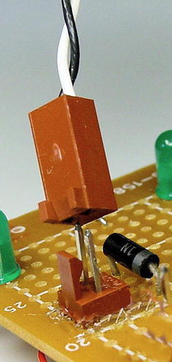
Figure 22-12. Molex KK female housing (top) connecting with male header (bottom) on the circuit board
A Molex KK connector consists of three parts (see Figure 22-13). First, there’s a male header, whose bottom portion is soldered to the circuit board. Then, there’s a metal terminal that is crimped (bent around) onto stripped wire. The terminal with attached wire is slid into the last part, which is the plastic female housing.

Figure 22-13. A Molex KK 2-pin connector consists of: (left to right) 2-pin male header, pair of terminals, and female housing
There are a couple of variations to the housing. Choose the housing with polarized ribs and locking ramp. The polarized ribs are small rectangular ridges on the ends of the housing. These ribs prevent the housing from accidentally being inserted onto the header either facing backwards or shifted over a pin. The locking ramp on the housing clips into the header so that the connection is unlikely to vibrate loose or to fall off if turned upside down.
A tool is necessary to force the metal terminal to wrap around and hold the wire for attachment (see Figure 22-14). You can use the crimp tool on a variety of connectors, not just the KK series.

Figure 22-14. Molex universal crimp tool (Molex #63811-1000)
Note that the metal terminal is not soldered to the wire. It’s pressed into a shape that embraces the wire. Interestingly, industrial strength motors or components that consume many amps of current can actually heat up solder enough to liquefy it. In those circumstances, crimped connections are the way to go.
Some builders do solder the terminal to the wire after crimping. Additionally, they add heat-shrink tubing to protect the terminal and keep it firmly in place in the housing. However, these steps are optional.
In total, the line-following robot requires the following connector parts:
- 5 two-pin headers
- 5 two-pin housings
- 1 four-pin header
- 1 four-pin housing
- 14 terminals (but, get some extra)
- 1 crimp tool
In all cases, the headers and housings should be 0.100-inch center (2.54 mm). The housings should all have locking ramps and polarizing ribs.
When you add up the total cost per connection, connectors are not inexpensive. Table 22-2 lists a few suppliers of the necessary Molex KK equipment.
Table 22-2. Suppliers of Molex KK Equipment and Parts

Attaching Molex KK Connectors to the Motors
The wires coming from the motors should already have about 0.35 cm of their plastic insulation stripped off, exposing bare wire.
- There are two sets of “flaps” on the metal terminal. Insert the wire into the terminal so that the bare wire is located at the inner set of flaps and the insulated portion of wire is located at the flaps on the end (see Figure 22-15). This is so that one set of flaps will be crimped over the bare wire to make an electrical connection and the other set of flaps will be crimped over the plastic insulation to mechanically hold the wire securely.

Figure 22-15. Wire inserted into terminal with plastic insulation in end flaps and bare wire in inner flaps
- Carefully insert the wire and terminal into the 1.6 mm diameter slot of the crimp tool, so that only the flaps over the bare portion of the wire will be crimped (see Figure 22-16). The flaps should point toward the numbers printed on the crimp tool.

Figure 22-16. Crimping the inner set of flaps on the terminal onto the stripped portion of the motor wire, while the outer set of flaps remains open over the plastic insulated portion of the motor wire
- Gently squeeze the crimp tool handles, causing the flaps to be curved over the stripped portion of the wire.
- Remove the terminal and wire.
- Insert the terminal and wire into the 1.8 mm diameter slot of the crimp tool, so that only the flaps over the insulated portion of the wire will be crimped. Again, the flaps should face toward the numbers. To do so, I need to flip the terminal upside down on my crimp tool.
- Gently squeeze the crimp tool handles, causing the flaps to be curved over the insulated portion of the wire.
- When complete, the terminal and wire should look like Figure 22-17. Because there are two sets of flaps being crimped over two thicknesses of wire, you have to crimp each set of flaps individually in different-size diameter slots of the crimp tool.

Figure 22-17. Two crimps attaching wire to terminal
- Repeat the process to add terminals to all four wires on the pair of motors.
- Insert the terminals into the housing with the loop facing the polarizing ribs (see Figure 22-18).

Figure 22-18. Terminal being inserted into KK housing
- On the underside of the terminal is a tiny piece of metal bent outward, (not the big loop, but the fragment on the reverse side) called a locking tang. The tang snaps into an open window at the bottom of the housing. You’ll hear a click when the terminal has been pushed all the way in, and the entire tang will be viewable in the housing’s window.
Until the tang is completely visible, the terminal isn’t fully seated in the housing. You can tug on the wire and pull it out. Without the locking tang in place against the housing window’s shelf, the terminal and wire would be pushed out when the housing is connected to the header on the circuit board.
What happens if you discover you’ve accidentally inserted the wired terminals in a different arrangement than you soldered the header on your circuit board? With a tiny screwdriver, you can push against the tang in the window of the housing while simultaneously pulling on the wire (see Figure 22-19). The terminal and wire will slide back out. Afterwards, you’ll need to bend the tang outward again in order for it to lock back in the housing.

Figure 22-19. Pushing down on locking tang to remove terminal from housing
- Insert the remaining wired terminals into their housings.
Facing the windows in the housing with the wires pointed downward, I choose to connect the negative wire from the motor on the left side, and the positive wire on the right. It doesn’t matter so long as you’re consistent with your circuit board and both motors.
- Hold the motor in one hand and the connector housing in the other hand.
- Twist the housing about ten times, so that the pair of wires twist together (see Figure 22-20). Not only does this prevent the wires from becoming tangled with other wires in the robot, but also it cancels out some of the electrical noise generated by the motors.

Figure 22-20. Motor with heat-shrink tubing protecting soldered terminals and twisted wire ending in KK connector
Congratulations, the motors are complete! The motors now have color-coded wires soldered to them, the terminals and solder joints are protected with plastic heat-shrink tubing, and the wire ends in a finger-friendly connector.
Putting Together the Line-Following Switch
The line-following switch was the only part of the circuit that wasn’t prototyped on a solderless breadboard. This is because the switches available with the necessary switching characteristics have thick and widely spaced terminals that don’t fit in a solderless breadboard.
The purpose of the line-following switch is to connect the motors to the transistors. In different switch positions, the motors will be hooked to different transistors, if at all.
When the switch is toggled to the center position, both motors are disconnected. This aids debugging and allows the robot to be placed on a starting line.
When the switch is toggled to the left position, the motors are connected in a straightforward manner, with the left motor connected to the left transistor and the right motor connected to the right transistor. This causes the left motor to activate whenever the left sensors detect brighter light.
When the switch is toggled to the right position, the motors are connected in the opposite way, with the left motor being connected to the right transistor and the right motor connected to the left transistor. This causes the left motor to activate whenever the right sensors detect brighter light.
The robot follows a dark line or a bright line based on whether the motors connect to the sensors on the same side or opposite side. Graphic details of this motion will be revealed in a later chapter.
Obtaining the Line-Following Switch
The line-following switch is a DPDT (double-pole double-throw) center-off toggle switch. Some suppliers list the switch as “on-off-on.”
Don’t purchase a switch for the line-following robot that has parentheses around one or more of the terms, such as “(on)-off-on” or uses the term mom, such as “mom-off-on”. This indicates a momentary position returned to the center by a spring. That’s beneficial for some projects, but, for this robot, you want the switch to stay in position even after your finger is removed.
The meaning of the “center off” term is obvious. The switch is turned off (no connections are made) when the switch is in the center position.
“Double pole” means that the switch can control two separate components at the same time. This is important, since the line-following robot has two motors that need to be controlled through the same switch.
“Double throw” means that each pole can be switched to make two different connections. This is important, since each motor needs to be connected to either the left transistor or the right transistor.
Table 22-3 lists suppliers of appropriate switches. However, sometimes it’s better to see and feel a switch in person, before buying. The size, shape, and color of external switches define the look and feel of the robot. Pick a switch that is consistent with the style of your robot.
Table 22-3. Suppliers of Subminiature DPDT Center-Off Toggle Switches
|
Supplier |
Part Number |
Price |
|---|---|---|
|
Jameco |
21952 |
$1.95 |
|
Jameco |
22841 |
$1.95 |
|
Electronix Express |
17TOGDDC-M |
$1.95 |
|
Digi-Key |
EG2414 |
$3.30 |
“Subminiature” refers to the approximate size of the switch. Even though it sounds small, you’ll be surprised at how big subminiature really is.
Don’t buy cheap or smaller (micro-miniature) switches. The plastic melts as you attempt to solder on the wires. You’re left with a switch that either doesn’t toggle at all or fails intermittently.
Preparing and Attaching the Switch Wires
Like the motors, the switch terminals need to have stranded wires soldered to them and then be covered with heat-shrink tubing (see Figure 22-21). Unlike the two-pin Molex connector attached to each motor, the switch ends in a four-pin Molex connector. The four pins are wired as follows: right motor, right transistor, left transistor, and left motor.

Figure 22-21. DPDT center-off switch (left), heat-shrink tubing (center), and various lengths of wire (right)
To make the wires more identifiable, use different colors. I chose yellow and green for the transistor outputs, which matches the LED colors. I chose white and red for the motors, since they’re both receiving positive voltage.
To make the wires fit into the small eyelets in the switch terminals, use thinner wire than was used with the motors. Instead of #22 AWG, I chose #26 AWG (bigger numbers indicate smaller wire) for the switch.
- Cut four wires total (one each of white, yellow, green, and red) to a length of 15 cm.
- Strip 0.75 cm of plastic insulation from one end of each wire.
- Strip 0.35 cm of plastic insulation from the other end of each wire.
- Cut two more wires (red and white) to a length of about 6 cm.
- Strip 0.75 cm of plastic insulation from both ends of both 6 cm wires.
- Cut one piece of yellow, one piece of green, two pieces of red, and two pieces of white heat shrink tubing (six pieces total) to a length of 1.5 cm.
Soldering the Line-Following Switch
A DPDT switch has six terminals: Three terminals for the first pole and three terminals for the second pole. Depending on the position of the switch, the center terminals can be switched to connect to the first terminals, no terminals, or the third terminals.
- Loop the green wire through the eyelet in a center terminal, twist the wire together, and solder (see Figure 22-22). This is the same technique used to connect wires to the motors.

Figure 22-22. Left and right transistor outputs soldered to the switch’s center terminals
- Loop the yellow wire through the eyelet in the other center terminal, twist the wire together, and solder.
The center terminals will have power rushing from the transistors to the motors. At the present time, since nothing is connected to the remaining switch terminals, the power doesn’t reach the motors, so the robot won’t move. The same thing occurs when the switch is in the center position: The switch doesn’t internally connect the center terminals to either side terminals, thus the motors aren’t connected to transistor power and the robot won’t move.
- Loop one end of the 6 cm red wire and one end of the 15 cm red wire together to the same terminal. You can pick any of the remaining terminals. I arbitrarily chose the lower right terminal in Figure 22-23. Twist together and solder.

Figure 22-23. Diagonal side terminals covered in heat-shrink tubing and connected to left motor
Got it? You have two red wires, one long and one short, connecting to the same terminal.
- Slide both pieces of red heat-shrink tubing over the pair of red wires.
- Loop, twist, and solder the other end of the 6 cm red wire to the terminal on the diagonal across the switch.
If one neglects to slide the heat-shrink tubing onto the red wires in step 10, the tubing can’t be added after step 11 because both ends of the short wire will be soldered to the switch.
Figure 22-23 shows the state of the switch as of completing step 11. The yellow and green wires are soldered to the center terminals. Two red wires are soldered to the lower right terminal of the switch and are covered by a piece of heat-shrink tubing. The other end of the shorter red wire is soldered to the terminal diagonally opposite it, and covered in heat-shrink tubing.
Reasoning Behind the Diagonal Cross Over
Let’s say the 15 cm red wire is connected to the left motor. It’s very important that the red wire leading to the left motor is connected to opposite terminals on each pole (the diagonal crossover).
Here’s why: Electricity flows into the green wire from the left transistor. When the switch is toggled in one direction, the green and red wires are electrically connected and power from the left transistor flows into the left motor. When the switch is toggled in the other direction, the yellow and red wires are electrically connected, and power from the right transistor flows into the left motor.
If the two red wires were connected to each terminal on the same pole, then the left motor would always be connected to the left transistor no matter whether the switch were toggled left or right.
If the two red wires were connected to each terminal on the same side of the switch, then the left motor would be connected or disconnected to both left and right transistors at the same time.
The crossover forces each motor to be connected to only one transistor at a time and the opposite transistor when the switch is flipped. If none of this makes sense, just trust me and follow the directions.
Finishing Soldering the Line-Following Switch
Follow the same steps with the white wire and the two remaining terminals. That is:
- Loop one end of the 6 cm white wire and one end of the 15 cm white wire together to the same terminal. You can pick any of the remaining terminals. I arbitrarily chose the upper right terminal as it appears in Figure 22-23. Twist together and solder.
- Slide both pieces of white heat-shrink tubing over the pair of white wires now soldered to the switch.
- Loop, twist, and solder the other end of the 6 cm white wire to the terminal on the diagonal across the switch.
All six terminals on the switch should now be wired (see Figure 22-24).

Figure 22-24. Finished switch with transistor outputs in center, left, and right motors connected to diagonally opposite terminals
You can test the arrangement by hooking a multimeter to either center wire and testing the continuity to the red and white wires while toggling the switch. Does the green wire connect to the white wire, off, and then red wire? Does the yellow wire connect to the red wire, off, and then the white wire?
- Shrink the tubing in place using a hair dryer or heat gun.
- Crimp Molex terminals onto all four of the switch wires.
- Insert the terminals into the Molex KK four-pin housing.
Facing the windows in the housing with the wires pointed downward, I choose to connect the wires in the following left-to-right order: white wire (right motor), yellow wire (right transistor), green wire (left transistor), and red wire (left motor). It doesn’t matter so long as you’re consistent with those connections on your line-following circuit board.
The switch is complete.
Putting Together the Tube LED Circuit
The headlights and left/right brightness-indicator LEDs light up when the robot’s power switch is turned on. So, there isn’t really a need for a power indicator light. However, the plastic tube connecting the motors gave me an idea.
There is diverse assortment of colors of mini M&M candy tubes available. Sandwich has a yellow tube. By tossing a couple of red LEDs in the center of the tube, it’s dull yellow when power is off but glows red whenever power is on (see Figure 22-25). It looks magnificent!

Figure 22-25. Glowing center tube
Examining the Tube LED Circuit Schematic
You can skip the tube-glowing circuit if you want, since it’s purely for aesthetics. However, the schematic in Figure 22-26 shows how easy it is to make.

Figure 22-26. Schematic of the tube LED circuit
The LED colors aren’t listed on the schematic, but you’ll want to select an LED color that contrasts with the color of the plastic tube you choose. Choose the highest-brightness LEDs you can find because the opaque plastic of the tube absorbs much of the light. Wide-angle LEDs are desirable, as they’ll light the tube evenly rather than having a few obvious bright-spots.
Building the Tube LED Circuit
The resistor and LEDs chain together in a column. Considering that, and the small number of parts, you can solder the circuit together without a circuit board. See Figure 22-27 for an example.

Figure 22-27. Tube LED circuit implemented with three LEDs and a 150 Ω resistor soldered to a Molex KK connector
Try to solder the LEDs facing different directions, so the light won’t be focused on a single spot within the tube.
There is a possibility of the component leads accidentally touching each other in their scrunched-up state within the tube. To avoid that, cover the exposed joints with heat-shrink tubing. At the very least, cover the joint that connects the resistor to positive voltage. That way, even if a short circuit occurs down the line, power must always pass through the resistor.
Finishing Up
Besides the main circuit board, only a couple of components remain to be completed. The 9 V battery snap doesn’t require soldering, only a Molex connector needs be crimped on the end.
The power switch is as easy to prepare as the motor: Solder two wires, cover with heat-shrink tubing, add a Molex connecter, and twist the wires together.
Because of the relatively low voltage and current consumed by the robot, almost any type of switch will do. Most power switches are rated at several amps (A) and 125 VAC or 250 VAC. That’s more than rugged enough to handle 0.5 A at 9 VDC.
If you want an illuminated power switch, be sure the built-in light’s voltage is appropriate for the robot. If the voltage rating is too high, it’ll just waste the low-level DC power it receives without providing sufficient light. If the voltage rating is too low, the bulb will pop. Maybe it’s better to avoid an illuminated power switch.
It’s worth selecting a switch in person rather than through a catalog so you can find one that looks cool and feels good. Table 22-4 shows the part numbers of some power switches that fit nicely with Sandwich’s body.
Table 22-4. Attractive Power Switches for Sandwich

Assuming you are going to mount the power switch inside of a plastic sandwich container instead of soldering it to a board, be sure to purchase a panel mount switch that has threads and a nut (see Figure 22-28). All of the switches in Tables 22-3 and 22-4 meet those criteria. Avoid a “snap in” style switch, as they are designed for a rigid structure (usually metal) of a specific thickness.

Figure 22-28. Rocker switch (left) and paddle switch (center) with threads and nut. Avoid “snap in” style switches (right) for Sandwich
Soldering Experience
Review Figure 22-1 (presented at the beginning of this chapter). Make sure that you’ve finished each item and that your finished parts look similar to those in the photograph.
Hopefully, learning to solder has been a positive experience for you. Soldering is a powerful skill with which you can create a whole new class of robot circuits. With practice, not only will you produce better joints, but also you’ll gain an intuitive sense for when a joint isn’t quite right.
Including connectors in your arsenal of robot parts complements soldered connections. The time spent in crimping pays off tenfold in serviceability. As your robots grow in complexity, connectors lend themselves to modularity. You’ll begin designing parts that you can swap between robots.
The main circuit board awaits you as your next soldering challenge. After all, you need something to connect to all of those parts.