
The concentration of horsepower on stage when driving wagons, lifting platforms, and hoisting scenery presents serious risk to the safety of performers, technicians, and audience members, as well as potential damage to costly stage equipment. People who set foot on stage or take a seat in the audience implicitly trust that we, as automation professionals, have analyzed the risks of mechanized movement and implemented safeguards to mitigate those risks. It is our professional duty to rigorously meet those expectations and thereby keep people safe from injury and prevent damage to property.
Safety measures are not layered onto an existing system as an afterthought, rather safety must be considered as an integral component of the equipment design and system integration. It is not a separate part of the Pentagon of Power, but rather a consideration made at each point. Safety-related decisions are made at each level of the automation system. As the individual machinery and controls are designed, the risks must be assessed and subsequently reduced to produce safe equipment. As you place winches, hoists, turntables, and lifts onto drawings of the production design, the entire stage should be analyzed as a large-scale machine with interconnected mechanisms and new risks that arise from the composition must be assessed. Assessing risks, and introducing safeguards to make those risks acceptable, is the goal of safety systems in automation.
To begin risk assessment, organize a group of competent people to identify the limits of the machinery, the potential hazards presented by the machinery, estimate the risks, and find solutions to lower the risks to tolerable levels. The severity of harm for each hazard you identify is classified on a scale from trivial to death. The likelihood of its occurrence is classified on a scale from highly unlikely to certain. Based on the severity and statistical probability of occurrence, each risk is reduced until either the potential harm is attenuated, or the likelihood is lowered to an acceptable level.
It’s normal, at first encounter, to be lightly horrified by the sterile number-crunching of calculating the probability that your work may kill someone. It is a grim thought, and not one easily shaken once the seed is planted in your imagination. However, risks always surround us and we unconsciously run these calculations constantly throughout everyday life. There is no activity that is risk-free; achieving zero risk is impossible. Instead, we live by weighing risk and consequence to achieve an acceptable balance. Is it safe to cross the street when you can see a car is heading towards the crosswalk? Well, how far away is the car? Four blocks away? No sweat, I’m going to cross. Fifty feet? No way, I’ll just wait. Should I board this flight when I know that a plane crash will likely end in my death? Planes rarely crash and I’m not going to stay in my house all my life – onward and upward. Should I stay in my house all my life to avoid injury? I’ll die of heart disease from lack of activity. These are all instinctive risk assessments that are no less grim, instead these assessments just lack engineering formality. Becoming comfortable talking openly and plainly about the risks in each automated effect, and their combined risks, is essential to increasing safety on stage. The severity of what we are doing is real, thereby making it critical we acknowledge and treat it with deserved gravitas.
After you acclimatize to the idea of objectively gauging risks, the next essential element to embrace is working with a group of competent peers to participate in the analysis. We all have blind spots in our technical knowledge and when engaged in risk analysis we cannot allow our personal shortcomings to negatively affect the people who are relying on us to keep the stage safe. Discussing and documenting all the potential risks should not be done in isolation but rather as a group. More minds are useful to poke holes in the weaknesses of a design. Personal pride in the design of the machinery or system must be ignored and the group’s most critical eyes must sweep through every aspect. The goal is to find every potential weakness, any chink in the armor, drag it out into the light of scrutiny and write it down. Once all the risks are identified and quantified, each risk is reduced to an acceptable level either through improvements in the design, restricting access to the hazard, or by instituting good operating procedures.
Multiple methods have been developed to perform risk analysis. The American National Standards Institute (ANSI) E1.6-1-2012 standard, Entertainment Technology – Powered Hoist Systems, includes an example of risk assessment in Annex C that is based on ANSI B11.TR3-2000, Risk Assessment and Risk Reduction – A Guide to Estimate, Evaluate and Reduce Risks Associated with Machine Tools. It is a pragmatic and approachable method, freely available, that could easily be adopted by any automation production team. I encourage you to read both the ANSI E1.6-2012 standard,1 and the standards that guided the authors of Annex C, since we will use that as our example here to perform a risk analysis on a deck winch that is running a prop pallet. The risk assessment and reduction process, employed both by the ANSI E.16–2012 standard and others, is:
1.Identify the limits of the machinery.
2.Identify the tasks associated with the machinery and the hazards involved during each task.
3.Estimate the risk level of each hazard.
4.Employ risk reduction measures until the risk level is acceptable.
Identify Limits of the Machinery
To identify the limits of the machinery and controls that are used to create an automated effect, write down the specified ratings of the system. A reasonable starting point for a list of limits is:
1.Intended use of the machine.
2.Duty-cycle.
3.Speed and load ratings.
4.Space requirements, including any area required around the machine for maintenance.
5.Weight of the machine.
6.Environmental limits such as ratings for indoor or outdoor use, and tolerance for dirt and contamination.
7.Mounting requirements.
8.Power requirements.
Using our example of a deck winch moving a prop pallet, the limits of the machine would be:

Figure 10.1Deck winch with a prop pallet
| System limitation | Value |
| Intended use | The deck winch is meant for lateral moves only. Vertical applications not allowed. |
| Duty cycle | Amplifier has a brake resistor with a 10% duty cycle and a maximum 5-second duration at full-torque. High-inertia decelerations require a 50-second rest. |
| Speed rating | Maximum speed is 36 in/sec. |
| Load rating | Estimated max wagon load in show is 500 lb requiring no more than 75 lb line pull. Winch capable of 550 lb of line pull. |
| Space requirements | 18 in x 30 in footprint. Area in front of winch must be kept accessible for periodic cable tension adjustment. |
| Weight of machine | 400 lb |
| Environmental ratings | Indoor use only. Moving parts must be kept free of debris. |
| Mounting requirements | Secure anchoring to stage floor or show deck through bottom frame of winch. |
| Power requirements | 230 VAC 3P 30 A |
Identify Tasks and Hazards
Working with your group, identify all the tasks involving the machine and associated hazards. This should cover the full lifespan of the production from load-in to strike so that ancillary hazards aren’t ignored. The following is a list of potential hazards that exist in a variety of automated effects from deck winches, hoists, and lifts.
| Category | Hazard | Common examples |
| Mechanical | Crushing | •Falling objects from hoists. •Caught between wagons pulled by winches. •Standing beneath a lift. •Dropping equipment during installation. |
| Shearing | •Feet sticking beyond the lift platform as it passes through the trap opening in the show deck. •Limbs caught between the link bars of a scissor lift. | |
| Cutting/severing | •Sharp edges on scenery passing by performers. | |
| Entanglement | •Limbs or costumes drawn into winch lines. •Power and control cords routed along the floor. | |
| Drawing-in or trapping | •Limbs or costumes drawn into conveyors. | |
| Impact | •Hit by wagons that are pulled by winches. | |
| Friction or abrasion | •Fingers or limbs caught between friction drive wheels and the drive surface. | |
| High pressure fluid injection or ejection | •Improperly installing and striking hydraulic lines. | |
| Electrical | Shock | •Opening live control cabinets and contacting live components. •Abrasion of power cords attached to moving scenery. |
| Thermal | Burns, scalds | •Touching exposed brake resistors on amplifier cabinets. •Touching motors that are running under heavy load. |
| Freeze-burns | •Handling CO2 for fog effects that are often used in conjunction with automation. | |
| Materials | Suffocation | •CO2 fog trapped in elevator shafts beneath the stage. |
In our example, the deck winch may have the following hazards (and more) with the associated tasks:
| Task | Hazard |
| Installation | •Crushing when installing the winch. It’s heavy and could tip over, or crush a foot when lowered into place. •Entanglement when roping the winch. |
| Cue writing | •Crushing or impact when operator is jogging with obstructed sightlines and unaware technicians or performers are in the path of motion. •Entanglement of clothing caught in the winch line and/or winch drum. |
| Running the show | •Crushing or impact when operator executes a programmed motion and performers are in the path of motion. •Entanglement of clothing caught in the winch line and/or winch drum. •Crushing or impact when an executed cue runs beyond normal position due to feedback sensor failure. |
| Troubleshooting | •Electrical shock by touching live components inside control or amplifier cabinet. |
Risk Estimation
To guide risk reduction, we need an objective measure of each risk to determine if it requires abatement. We assign a numerical value to the severity and a numerical value to the probability. The product of the probability and severity is the risk. Mathematically, Risk = Probability × Severity. The chart below shows this method of calculating risk values, though other more rigorous methods can be used, as described later in this chapter.
| Risk rating | Probability of harm | |||||
| Remote | Unlikely | Likely | Very Likely | Certain | ||
| Severity of harm | Trivial injury | 1 | 2 | 3 | 4 | 5 |
| Injury without loss of work | 2 | 4 | 6 | 8 | 10 | |
| Injury with 3-day loss of work | 3 | 6 | 9 | 12 | 15 | |
| Major injury | 4 | 8 | 12 | 16 | 20 | |
| Death | 5 | 10 | 15 | 20 | 25 | |
| Risk Value | Acceptability |
| 1–4 | Acceptable |
| 5–8 | Acceptable only if risk is as low as is reasonably practicable |
| 9–25 | Unacceptable risk |
When assigning both a probability and severity rating, the highest credible value must be used. Subjective judgment is required to select a probability rating using this method, but it should take into account the following:
•Exposure
•How often does the hazardous situation occur on stage, and how long does it last for each instance?
•What is the level of bodily exposure to the hazard (fingers, hand, leg, whole body, etc.)?
•How many people (performers and technicians) will be in harm’s way?
•Will the general public be exposed?
•The level of skill of the personnel performing the task. Less skilled personnel are more likely to be harmed.
•Historical data of harm related to the task (near-misses and similar risks).
•Lighting conditions can reduce safety and increase likelihood of hazards.
•Noise can make it difficult for personnel to communicate and decreases the ability to focus.
•Extreme temperatures can impair judgment.
•Floor treatments can decrease traction and increase the chance of slipping.
•Human factors
•Complex, multi-step sequences may be executed out of sequence, or steps may be skipped. For instance, a stagehand may forget to clip a safety tether for a performer riding a lift.
•Poor communication between personnel who need to coordinate actions. For instance, stagehands that need to communicate a go/no go to initiate an automation sequence.
•Reliability of the functional safety system.
•Is there a safety rating for the equipment?
•Is the safety rating implemented in hardware with a known mean time to failure (MTTF).
•Is there software involved that carries a risk of systemic failure?
There are statistical probabilities used by some of the standards we will discuss later in this chapter, but if that data is unavailable for the task under consideration, it is worthwhile to build a consensus among your group about the probability of harm using the nomenclature in the chart above. Discussing it and then documenting your decision along with the rationale is valuable. Probing the issue and building a database of your analysis is important in increasing risk awareness in your production team.
Let’s look at some risk estimates for our example that would be part of the documentation process:
| Task | Installation |
| Hazard | Entanglement when roping the winch. |
| Comment | During setup, the end of a wire rope has to be terminated on the winch drum. Once terminated, the winch is powered and run as the rope is fed onto the drum. Because of the necessity for technicians to have their hands in the machine for the termination step, there is a serious hazard if the motor is powered up accidentally. The probability is heightened because of the chaotic work environment during load-in where several people may be requesting machines to be powered. |
| Severity | 4 |
| Probability | 3 |
| Risk level | 12 |
| Task | Cue writing |
| Hazard | Crushing or impact when operator is jogging with obstructed sightlines and unaware technicians or performers are in the path of motion. |
| Comment | Before programmed cues are finalized, the wagon will be jogged manually to set target positions. The operator has an obstructed line of sight and cannot see the entire path of motion. Performers and technicians will eventually learn when to expect movement, and at what locations, but early in the process it is surprising for them. |
| Severity | 3 |
| Probability | 3 |
| Risk level | 9 |
| Task | Running the show |
| Hazard | Entanglement of clothing caught in the winch line and/or winch drum. |
| Comment | The winch is placed offstage in the wings. During the performance it is dark in the wings. Performers cross near the machinery while it is operating. Some of the performers’ costumes include long skirts and coats that could easily fall into the winch drum. |
| Severity | 4 |
| Probability | 4 |
| Risk Level | 16 |
As you can see, even in our benign example of a prop pallet there are serious risks that require reduction.
Risk Reduction
To reduce risks to tolerable levels you can do the following, in order of effectiveness:
•Change the design of the machine or installation layout to reduce the risk or eliminate the hazard.
•Add safeguards to limit access to the hazard.
•Implement protocols and training to reduce the risk.
Whenever possible, it is best to change the design of the machinery, or alter the design of the automation layout. For example, if the presence of a machine on stage presents a hazard, moving it to the trap room where it is accessible by far fewer people will reduce the risk.
If the machine can produce more force than required, and that additional force presents a hazard, replacing the machine with a lower horsepower model reduces the potential for harm. If a failure of the equipment would present a hazard, adding redundancy to the system will reduce the risk. These are just some of the ways where a design change can lower the risk.
If a design change is impractical, adding safeguards to keep people away from the hazard will reduce risk. Adding safety guards or interlocking barriers that will prevent operation if removed has the highest impact on risk reduction. Safety guards that can be easily defeated are still effective, but less so since this relies on personnel having proper training and motivation to leave the guards installed.
Developing operating procedures and protocols to prevent exposure to the hazard will reduce risk levels, but it is clearly not as reliable as the preceding options. Training is crucial, and safety protocols should be instituted on stage, but their effect isn’t as great.
Often, we will combine multiple techniques to achieve tolerable risk levels. By analogy, if you wanted to limit the risk of injury when using a table saw you could tell people to keep their hands away from the blade, install a saw guard, or purchase a Saw Stop that is equipped with a safety device that stops the blade when it touches skin. In practice, you’d likely do all three. Similarly, when analyzing an automation system for a production, we must have safety protocols and trained personnel, but we will employ design changes and add safeguards to get better results.
To complete our example, let’s look at some options for risk reduction.
| Task | Cue writing |
| Hazard | Crushing or impact when operator is jogging with obstructed sightlines and technicians or performers are in the path of motion unaware. |
| Comment | Before programmed cues are finalized, the wagon will be jogged manually to set target positions. The operator has an obstructed line of sight and cannot see the entire path of motion. Performers and technicians will eventually learn when to expect movement, and at what locations, but early in the process it is surprising for them. |
| Severity | 3 |
| Probability | 3 |
| Risk level | 9 |
| Risk reduction method | To improve the operator’s sightlines we will add cameras on stage and monitors at the automation desk. Additionally, we will implement a safety protocol that requires an Assistant Stage Manager (ASM) near the moving wagon. The ASM will communicate with performers and technicians on stage about the pending motion. The automation operator (AO) will await a “CLEAR TO MOVE” message from the ASM, then the AO will confirm with a “MOVING” message followed by a “MOVEMENT COMPLETE” message to let the ASM know motion is finished. |
| Severity | 3 |
| Probability | 2 |
| Residual risk | 6 |
| Comment | If we wanted to reduce the risk further, a safety bumper could be integrated into the wagon so that it stopped when it made trivial contact with anything on stage. However, the additional complexity and erroneous stopping is not normally worth it. The combination of a change to the design to improve sightlines and a safety protocol should be effective enough in this instance. |
| Task | Running the show |
| Hazard | Entanglement of clothing caught in the winch line and/or winch drum. |
| Comment | The winch is placed offstage in the wings. During the performance, it is dark in the wings. Performers cross near the machinery while it is operating. Some of the performers’ costumes include long skirts and coats that could easily fall into the winch drum. |
| Severity | 4 |
| Probability | 4 |
| Risk level | 16 |
| Risk reduction method | We will add a polycarbonate enclosure to the winch frame. Every access to the hazard area will be shielded to keep costumes from being snagged in the drum. Any exposed wire ropes from the deck track will be covered with plywood flooring leaving no access to the hazard. The shields are not interlocked with the machinery power, so part of the pre-show protocol check is to confirm that all guards are still in place. |
| Severity | 4 |
| Probability | 1 |
| Residual risk | 4 |
| Comment | Using safety shields is a reasonable approach. Potentially moving the winch to a trap room with limited access would be another method. Since the machine can still run even if the safeguards are removed, we must add a safety protocol to the operating procedure to confirm that the guards are still in place and weren’t left off after a maintenance call. |
Documentation
Each risk analysis should be documented and kept on file. The above examples are perhaps obvious, and there may be other solutions that would achieve similar or better results. But, you can communicate the risks and the techniques used to mitigate those risks to your team by documenting them in a formal process. Hopefully, you will avoid any injuries by using the process, but if someone is injured then you can revisit the analysis to figure out what went wrong. Too often we, as an industry, have reacted to a tragic accident by instituting a safety measure after the fact. While it’s good to learn from mistakes, using risk analysis forces us to think about sources of accidents before we make the next mistake. The next page offers a sample template that can be used or altered to fit your process.

Figure 10.2Risk analysis template
Though safety standards that encompass the entire stage system, or even a single automated effect, have been slow to come to the United States, European standards have existed for decades and continue to evolve. The guidance in the European standards is useful to those of us in the US, even if the standards aren’t compulsory here.
Machinery Directive
In 1995, the European Union created the Machinery Directive to increase public safety. With the ever-increasing number of machines used both in the workplace and private life, the EU compelled machinery manufacturers to certify the safety of their products by conforming to new standards and indicate compliance by applying the CE mark (Conformité Européenne). The directive is broad and holistic in its view of automated equipment, concerning itself with not just fire safety, electrical safety, or physical safety, but all aspects of the machine and the associated controls that enable the intended use. To support the directive, several standards were created for guidance, many of which have been revised and new versions have superseded the original efforts. The standards are required reading for manufacturers and system builders that wish to sell products in the EU market, but may be useful for anyone interested in the design of safe machinery and controls.
When perusing the standards and directives, it’s helpful to have a little explanation on some of the vocabulary and abbreviations used.
Directive – An EU law which requires the governments of member states to achieve the written result of the law without mandating the means of achieving the result.
EN – A standards document that has been ratified by a European Standardization Organization (ESO). The three ESOs are the CEN, CENELEC, or ETSI. A harmonized standard, or EN, gives guidance to comply with a Directive.
ISO – The International Organization for Standardization develops and publishes standards that may be the basis for an EN standard.
IEC – The International Electrotechnical Commission develops and publishes standards on electric and electronic products. These standards may also be the basis for an EN standard.
The following standards are a sampling of the most pertinent to our industry. I want you to have seen the names of the standards and to know that you can come back to this book as a reference for brief standard descriptions as they arise in your work.
IEC 61508
IEC 61508 is a standard that addresses functional safety in electrical and electronic systems. The concept of a Safety Integrity Level (SIL) is used in this standard. It describes protective standards to guard against both systematic failure and random hardware failure by assigning an integrity level. Modern systems make use of electromechanical devices, solid-state discrete components, and programmable logic devices stuffed with transistors and software. Single-purpose discrete devices, such as switches and relays, have a quantifiable mean time to failure (MTTF) and thus their reliability is calculable. Complex systems and programmable systems are susceptible to systematic failure that is brought about by timing of events, design tolerance, and software bugs. In such systems, the reliability is determined by the quality of the design and implementation, not by the hours of use. Software doesn’t wear out over time like a contact in a switch. It breaks because it is poorly written. Such failure is not predictable as a function of time but rather the events encountered as the software runs. A software bug may present symptoms within seconds of a program’s execution or years later. Qualitative risks don’t grow over time; the risk is constant. IEC 61508 defines risk levels and methods to reduce risks, both quantitative and qualitative, to those levels through rigorous design and documentation.
IEC 61508 describes four levels of safety integrity: SIL4, SIL3, SIL2, SIL1. The most rigorous is SIL4, and the least is SIL1. These levels quantify the reliability of the system that holds the rating. There are two categories of systems to be considered when assessing reliability: high-demand rate and low-demand rate. Safety systems that are called to act more than once a year are high-demand. If a safety system is called into action less than once per year, it is considered low-demand. This distinction is necessary since some safety systems operate frequently, for instance the circuitry involved in engaging the brakes of a hoist at the completion of each movement. Other systems are rarely called into action, but their functioning is critical after staying dormant for prolonged periods, as is the case in an overspeed detection system that will engage a hoist’s brakes if the motor fails during motion. The acceptable probabilities of failure for the SIL levels are shown below. Note that the rates are not given in the same units. High-demand rates are given as failures per hour. Low-demand rates are given as probability of failure on demand.
| SIL | High-demand rate (dangerous failures per hour) |
Low-demand rate (probability of failure on demand) |
| 4 | >= 10–9 to < 10–8 | >= 10–5 to < 10–4 |
| 3 | >= 10–8 to < 10–7 | >= 10–4 to < 10–3 |
| 2 | >= 10–7 to < 10–6 | >= 10–3 to < 10–2 |
| 1 | >= 10–6 to < 10–5 | >= 10–2 to < 10–1 |
These rates of failure are a bit hard to put into perspective. In practice, SIL4 ratings are nearly always impractical because of the expense and sophistication to achieve that level of reliability. SIL3 is often applied to Emergency Stop systems and other high-risk systems on stage, such as hoisting and lifting. SIL2 is more often appropriate for lateral movements. SIL1 is not effective for safety-critical systems.
Many scenic automation systems in the US lack a SIL rating entirely, or have obtained a SIL rating for a portion of the system, most commonly the Emergency Stop system. However, most, if not all, utilize SIL-rated components. Using those components is a good practice, but doesn’t imply a SIL rating for the system. The point of a Safety Integrity Level is to analyze the entire system, or subsystem, with all components functioning together as designed. If SIL-rated components are strung together in a substandard design, it undermines the rating of the individual components. To obtain a safety certification with a SIL rating that conforms to IEC 61508, the manufacturer or system integrator must work with an independent certification company. There are several certification companies, or certification bodies, but perhaps the best-known is TÜV SÜD.
EN 62061
The requirements of IEC 61058 were used as the basis for EN 62061, which is harmonized to the Machinery Directive.
EN ISO 13849-1
EN 954-1 was an earlier safety standard which supported the Machinery Directive. It has been superseded by EN ISO 13849-1. Like IEC 61508, and correspondingly EN 62061, EN ISO 13849-1 uses the concept of functional safety, in other words the behavior of the machine required to achieve a safe risk level. Both standards recommend a risk assessment and reduction process to limit hazard levels which achieve similar results, though they differ in approach.
While EN 62061 uses a Cartesian chart to map probability and severity of a hazard onto a SIL level, EN ISO 13849-1 uses Performance Levels (PL). There are five Performance Levels, ranging from the least demanding to the most demanding. The least demanding Performance Level is “a” and the most demanding Performance Level is “e.” To find the proper Performance Level, a horizontal assessment tree graph is used.
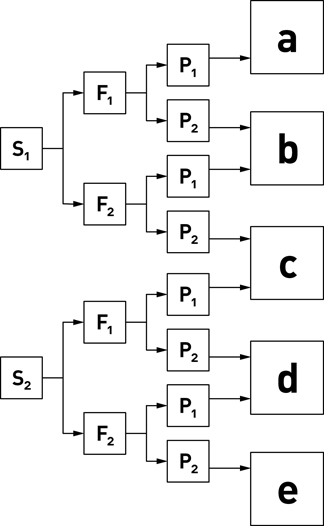
Figure 10.3Performance Level risk graph
S1 = Slight (normally reversible injury)
S2 = Serious (normally irreversible injury or death)
Frequency and/or exposure time to the hazard
F1 = Seldom to less often and/or the exposure time is short
F2 = Frequent to continuous and/or the exposure time is long
Possibility of avoiding the hazard of limiting the harm
P1 = Possible under specific conditions
P2 = Scarcely possible
The Performance Levels can also be expressed as a probability.
| Performance Level (PL) | Average probability of dangerous failure per hour |
| a | >= 10–5 to < 10–4 |
| b | >= 3 × 10⁻⁶ to < 10–5 |
| c | >= 10–6 to < 3 ×10⁻⁶ |
| d | >= 10–7 to < 10–6 |
| e | >= 10–8 to < 10–7 |
The following chart shows the equivalent Performance Level and SIL.
| PL | SIL | Average probability of dangerous failure per hour |
| a | N/A | >= 10–5 to < 10–4 |
| b | 1 | >= 3 × 10⁻⁶ to < 10–5 |
| c | 1 | >= 10–6 to < 3 ×10⁻⁶ |
| d | 2 | >= 10–7 to < 10–6 |
| e | 3 | >= 10–8 to < 10–7 |
| N/A | 4 | >= 10–9 to < 10–8 |
There isn’t a clear answer about which standard to follow since they overlap, unless you have a specific requirement to verify a system’s Safety Integrity Level (SIL) or Performance Level (PL). Most safety-rated components will include a rating for either standard.
BGV
Germany developed the BGV standard for rigging hoists. BGV is rapidly being adopted and commonly seen on electric chain hoists. The standard impacts the manufacture of hoists, but gives end-users easy to follow ratings to guide questions of suitability of a product. There are three ratings to cover the common hoisting scenarios and their safety requirements.
A hoist marked with a D8 rating is suitable for lifting a load into position, but the load must be secured with another device before people can pass underneath the load.
A hoist marked with a D8+ rating can be used for lifting load without people beneath the load. The load may be statically suspended above people.
A hoist marked with a C1 rating can be used to lift and suspend loads above people. This rating requires a controller and load sensor monitoring.
ESTA Technical Standards Program
ESTA established the Technical Standards Program in 1994 to codify entertainment-specific standards. In recent years, the program has published standards concerning automation. These standards are freely available and easily accessible to any technician interested in improving the safety of machinery onstage. Some of the highlights are:
ANSI E1.6-1 – 2012 Entertainment Technology – Powered Hoist Systems
This standard specifies requirements for the design, manufacture, installation, inspection, and maintenance of powered hoists used in live performances.
ANSI E1.43: 2016 Entertainment Technology – Performer Flying Systems
Though beyond the scope of this book, automated performer flying has become common in live performance. This standard addresses the design, manufacture, and installation of performer flying systems, including those that are automated.
ANSI E1.42: 2016 Entertainment Technology – Design, Installation, and Use of Orchestra Pit Lifts
Narrow in its scope, this standard addresses Orchestra Pit Lifts. Though it is not intended for performance-capable lifts, it includes interesting concepts that are useful for lifting applications.
With all the talk of standards and risk assessment, you may well be wondering how you should, uh, you know, do it. How do you make automated effects safer? Once you have assessed the risks and found intolerably high risks, how do you reduce those risks? There are concepts and components that you can employ to reduce risk. The first concept we must nail down is Failsafe; it is the foundation upon which safety rests.
To be failsafe does not mean that a component, circuit, or system is immune to failure. As mentioned during risk assessment, everything fails eventually, but something that is failsafe will return to a safe condition when it fails. Most of the time in automation that means when a component or system fails, it should stop moving. A few examples will help reinforce this idea.
End-of-Travel Limit Switches
Limit switches, introduced in Chapter 6, are simple feedback sensors that have normally open (NO) and normally closed (NC) switch contacts that activate when the actuator is pressed by a physical object such as a piece of scenery or part of a machine. The most common use of a limit switch is when it is employed to sense the end of travel for a machine. For instance, the furthest onstage and offstage points on a deck track could have limit switches struck by the dog. The master carrier running in a traveler track might strike limit switches installed on the SR and SL ends of the track. A scissor lift platform will raise up until it contacts a limit switch, and lower until it contacts another limit switch.
Limit switches that are used as end-of-travel sensors are wired as Normally Closed (NC) switches to make the circuit failsafe. The Control in the system will send a current through the switch constantly. If that current is interrupted, the Control will not allow any further motion in the direction of the switch.
There will be a signal for both the forward and reverse directions. If the forward limit signal is interrupted, then the machine will only be able to move in reverse. Conversely, if the reverse limit signal is interrupted, then the machine will only be able to move forward. Should both signals be interrupted, the machine will be unable to move in either direction. If the signal is interrupted because the wire is cut, or the limit is unplugged from the control, the motion will stop.
In this way, the control can detect a problem with the signal wiring and stop. It is the absence of the signal that will stop the motion. To consider the alternative, imagine the signal was designed to only transmit when the switch was struck using an NO contact. If a deck dog was traveling along a track, heading towards a limit switch that was unplugged, the dog would contact the switch but no signal could be sent. The control would be blind to the malfunction and allow the dog to drive into the end of the track and break the deck rigging. When properly designed as a failsafe circuit, with a constant current flowing through the NC contacts in the limit switch, the control will shut off the deck winch as soon as the cable is unplugged.
End-of-travel limit switches are important in all automated effects that have a physical boundary such as winch tracks, traveler tracks, and lifts. Many turntables won’t require physical limit switches, provided they can spin freely for unlimited revolutions. For linear effects, the limits are necessary to keep the machinery from tracking too far either when operated manually or as a safeguard against positioning errors when running cues. If an encoder fails, or the position is reset improperly, the limit switch is the last sensor in the circuit to protect against a hazardous haul beyond the physical limits of the effect.
Hard Limits vs. Ultimate Limits
In machines where a failed limit switch presents an unacceptable risk, an additional set of limit switches are used. The first set of switches are called “hard limits” and the next set of switches are called “ultimate limits.” Hard limits are placed at the normal end-of-travel location for a machine. Ultimate limits are placed beyond the hard limits. Should the hard limits fail catastrophically, the ultimate limits will stop the machine before the failure wreaks havoc.

Figure 10.4Ultimate limit placement
When a machine activates a hard limit, movement is allowed in the opposite direction. The operator can run a cue or jog the motor away from the hard limit.
The ultimate limits behave differently than hard limits. If struck, the machine is either placed in an Emergency Stop condition or a special fault condition that is uniquely identified as an ultimate limit fault. Unlike hard limits, the machine cannot be moved off the ultimate limit through normal means of jogging or running a cue.
Either the limit must be physically released by walking over to the machine with a screwdriver, or an override switch is activated. If an override switch is employed, it will reduce the speed and limit the direction that the machine can be moved. Logically, the machine should never strike an ultimate limit, so if one has been activated a technician is required to go investigate the cause.
Spring-set Brakes

Figure 10.5Motor-side brake

Figure 10.6Motor-side and load-side brakes
Mechanical brakes are often fitted onto the motor of a machine, or placed directly on the output of the speed reducer, to hold the scenery in place when the motor isn’t moving. During a power failure, we want the brakes to hold the load rather than release it. These brakes are always Spring-set Brakes, also called Safety Brakes or Failsafe Brakes. The brakes are built with springs that engage when power is removed. To release the brake and allow the machine to spin, power must be applied to an electromagnet that pulls together to defeat the springs. This method of engaging the brake stands in contrast to the alternative of applying a braking force when power is applied. The spring-set brake is failsafe because it stops motion if power is ever lost, whether intentionally or unintentionally because of a severed cord or power failure.
Terrifying as it is, imagine a theatre full of hoists without failsafe brakes that required electricity to hold their loads. A power failure would cause all hoists to drop their suspended loads. Clearly, a spring-set brake is failsafe since it defaults to holding the load.
Emergency Stop
Emergency Stop systems will be a topic of continued discussion, but the basic circuit architecture should be failsafe. A machine should stop moving if the Emergency Stop signal is interrupted for any reason. Whether the system was activated by pressing one of the big red mushroom buttons, or an Emergency Stop signal cable was disconnected, the result should be the same: stop moving.
These are just three examples of failsafe design, but the concept should be considered when analyzing the safety around any hazard. Always consider how the system will respond if the signal in question is interrupted abnormally. Anticipate failure and design the system to default to a safe condition.
As a counter example, I once took a tech support call from a theatre that had grown concerned over the safety of the trap doors they built for a production. The doors were held in place by pneumatic cylinders with solenoid valves that could be activated from the automation system. Their design required the solenoid valves to be constantly energized for the doors to remain closed; if power was lost, the doors would drop open. They were alarmed to realize that activating the Emergency Stop removed power from the solenoid valves and dropped the doors open.

Figure 10.7Poor mechanism design for Emergency Stop
As I explained, the safest condition for the Emergency Stop is to remove power, since it was unsafe for the Emergency Stop to leave power in the system. Any machine in the system must be designed to fail safely when power is removed. As designed, their doors would open not only during an Emergency Stop, but also during a power outage, and, presumably, at the same time the lights would go out, leaving the stage pitch black with large holes open in the floor. Clearly, they needed to re-design the doors so that the doors would be held closed by a mechanical failsafe latch. The pneumatic cylinders should pull the latch to release the doors only when power was applied. A loss of air pressure or electrical power should not open the doors.

Figure 10.8Proper mechanism design for Emergency Stop
After a little bit of resistance, they agreed to go back to the drawing board and rebuild the doors to be failsafe. It’s a great example of how the failsafe concept should be considered from the outset when designing an effect.
Redundancy is another concept employed to reduce risk. When analyzing a machine, controller, effect, or system, identify anything whose failure would render the rest of the design unsafe. This single point of failure should be eliminated or fortified through redundancy.
Mechanically, redundancy can be achieved by increasing the number of components, adding a secondary mechanism, or both. For instance, a sunroof-style trap door may ride on rollers in a track. If any of those rollers fail, the trap door will become dangerously unstable and someone who steps on the door above the failed roller may drop through the floor.

Figure 10.9Sunroof trap with failed roller
Potentially, if the mechanism allows, another set of rollers could be added at each corner. This exact redundancy would increase the reliability of the mechanism because the probability of simultaneous failure in both rollers is exponentially more than that of a single roller failure under normal conditions. If the probability of dangerous failure is 10–4, then the probability of simultaneous failure is 10–4 x 10⁻⁴ or 10–8. However, this requires that we detect the first failure quickly and replace the defective part and restore the protection of the redundancy. A methodical inspection process to catch the broken part or sensor feedback that could detect the failure is necessary.
We could tackle the same issue by welding on heavy steel pins next to the rollers. If the rollers fail, the door will drop slightly onto the steel pins. In this case, the pins could have a much higher load rating, making them a better backup device. The pins would also alert the crew to the failure since the door would work in an uglier, noisier way. The noise would inspire faster response because it is more obvious and doesn’t rely on an inspection process. Though not as elegant as a squealing wear indicator on car brakes, the additional noise caused by dragging a door on steel pins will communicate the need for maintenance to the crew without creating a safety hazard.

Figure 10.10Sunroof trap with steel pins for redundancy
Electrically, a critical circuit could use several redundant components wired in series to increase reliability. A power circuit that should be interrupted by the absence of an Emergency Stop signal could place two contactors in series and wire the power source through both. Assuming the contactors have force-guided contacts, or mirrored contacts, the operation of both could be monitored by comparing the state of the coil voltage and the contacts. Again, the likelihood of simultaneous failure is exponentially higher than single failure, which greatly increases the reliability. With a monitoring circuit, the relays would not be allowed to re-energize if either had failed during the previous operation because of the welded contact.

Figure 10.11Safety relay with power contactors and monitoring circuit
Logically, using different data sources can increase reliability in control programming. When a safety controller needs to verify that a hoist has control of a load, two encoders might be placed on the machine. One encoder may be motor mounted, while the second is installed on the drum shaft. The first is incremental, the second is absolute, requiring different decoding. Both sensor readings should evaluate at the same time and deduce the same velocity and position. If an excessive speed is detected, or if an excessive difference is detected between the two, the controller can stop motion and alert you that the machine requires maintenance.

Figure 10.12Dual encoders to single control
Redundancy requires thorough consideration of the entire system. For instance, hoists used in lifting applications are required to have redundant mechanical brakes to meet current safety standards. The mechanical redundancy should also be supported by electrical and control redundancy. Having two physical brakes is of little use if both are incorrectly released because of a single-point failure in the control circuit. Follow the entire path from the initial button press to the mechanical motion, and insure that redundancies exist in the appropriate place to improve reliability of the system during its intended use.

Figure 10.13Showstopper 3 Consolette
Source: Courtesy of Creative Conners
When talking about safety, the Emergency Stop system and its big red mushroom button are often thought of first. Certainly the Emergency Stop is an important requirement of any automation system. When pressed, the Emergency Stop will cease all motion on the stage. It must:
•Stop all motion, overriding all other operations at all times.
•Remove potential energy from the system that can cause a hazard, either immediately or after time has elapsed for a safe deceleration, depending on the Stop Category.
•Require a second step to restart motion, not simply resume motion when reset.
•Be constructed from failsafe components and utilize failsafe circuitry.
Stop All Motion
Multiple Emergency Stop buttons may be placed around the stage to make it easy for any staff with line of sight to hazard areas to kill motion. Each Emergency Stop button should stop the entire system. When needing to make a quick decision about safety, staff shouldn’t have to remember which big red button will stop the machinery that is the source of danger. See a problem, smash a button.

Figure 10.14Multiple remote Emergency Stop stations
Stop Categories
There are three categories used for stopping machinery.
| Category | Operation | Suitable for Emergency Stop |
| 0 | Uncontrolled stop. Remove power instantly and apply mechanical brakes. | Yes, but high inertia loads could cause another potential hazard if stopped this quickly. |
| 1 | Controlled stop. Use power to slow the load in a brisk deceleration and then remove power and apply mechanical brakes. | Yes, but if deceleration isn’t possible because of equipment failure it becomes a Category 0 stop. |
| 2 | Controlled stop. Use power to decelerate the machine and maintain power to the system after stopped. | No. This is a normal stopping action that can only be executed in non-emergency situations. |
The simplest and most common circuitry for an Emergency Stop is a Category 0. As long as proper failsafe redundant circuitry is employed, this may be all that is required.
Heavy loads create very high forces under high acceleration or deceleration rates (force = mass × acceleration) and a Category 0 stop could create a hazard if these forces exceed the safe operating parameters of the machinery. A heavily loaded batten traveling at high speed presents a large force that may break the rigging during a Category 0 stop. In such cases, a Category 1 stop is required. The Category 1 stop will command the amplifier to begin a deceleration immediately and start a safety-rated timer. When the timer elapses, power is removed from the machine. If the amplifier is unable to decelerate the load, it becomes a Category 0 stop.
A Category 2 stop is a powered stop that does not remove power from the machine. This is not suitable for an Emergency Stop, but is still a useful feature to have at your disposal. When rehearsing a show, after initiating a cue you may hear a “Hold please,” over the headset. Rather than letting the cue continue, initiating a Category 2 stop to decelerate all machines and begin a restore is much gentler on the mechanics. In SpikemarkTM, this feature is called a Soft Stop, and it is only suitable if there is no hazard.
Reset Does Not Resume Motion
The Emergency Stop button is a red mushroom switch that activates by pressing down. To release the Emergency Stop button, you must twist the button clockwise and it will reset by springing upwards. Resetting the Emergency Stop must not start motion. Imagine you are running a cue and you realize that a performer has stepped into harm’s way of a wagon traveling on stage. You smack the Emergency Stop button to stop the winch. When you release the switch, nothing can move. The cue does not resume when you release the button. Instead, you must take explicit action to restart movement. This requirement prevents a hazardous situation from unexpectedly restarting.
Failsafe Components and Circuits
The Emergency Stop must not be rendered ineffective by a single fault, or an accumulation of faults. It must stop the machine, and if the Emergency Stop system has encountered an internal fault, the Emergency Stop must allow for system repair before re-energizing the machinery. To achieve this requirement, each component must be selected and wired appropriately.
The Emergency Stop button must be a latching red mushroom button with a twist-to-release latch with Normally Closed (NC) contacts. When the button is pressed, the NC contacts of the switch must open. The contacts must be direct-acting, not reliant on springs. If the contacts weld closed, applying pressure to the button will force the contacts open. To protect against the failure of a single contact in the switch, two switch contacts are used for redundancy. Each switch contact is monitored and compared. When the button is pressed, only one contact is required to initiate an Emergency Stop, but both must be operable to reset. This means that a single fault in a button will be tolerated and the safety function won’t be compromised. However, if you try to reset an Emergency Stop signal that has a faulty button, the system won’t reset which will alert you to a fault. A safety relay encapsulates this functionality in a convenient, pre-made package.

Figure 10.15Safety relay

Figure 10.16Two-channel Emergency Stop button with safety relay
The Emergency Stop circuit must be normally energized. If the energized circuit is interrupted for any reason, an Emergency Stop will be initiated. This protects against cable failure, power failure, or other connection issues between the Emergency Stop signal source and the machines it governs.
To interrupt the power source to a machine, you can either use discrete relays and contactors or integrated safety functions in the amplifier. To use discrete relays and contactors, the circuit must use redundant, self-monitoring, force-guided contacts. While it is possible to build the circuitry that reliably responds to an Emergency Stop signal, it is more practical to purchase a pre-made and safety-rated module. These safety relays have all the appropriate safety circuitry built into a convenient DIN rail module, but they do not have the current capacity to switch the power source to most power amplifiers directly. Instead, the safety relay is used to energize the coils of larger power contactors that can handle the current demands of a VFD, servo drive, or another amplifier. Two power contactors are used in series for redundancy to ensure that a single fault will not compromise the Emergency Stop. Each contactor must have force-guided contacts (aka mirrored contacts or positively driven contacts) with a combination of NO power contacts and NO signal contacts. When the safety relay deems it safe to allow power to the amplifier, and thus the machine, it will send current to the coils of the power contactors. The power contactors will activate and close the power circuits and open the signal contacts. Since the contacts are force-guided, if any power circuit contact is welded shut, the signal circuit will remain open. The safety relay monitors the signal circuit to confirm that the power contactor is behaving correctly. If it detects abnormal operation, it will not reset and will leave the power contacts open until the defective contactor is replaced. This means that a single faulty contactor will not impede the safety function of the circuit.

Figure 10.17Safety relay with redundant power contactors
Integrated Safety Functions
VFDs and servo amplifiers are being built with integrated safety functions that reduce the number of components and complexity of wiring needed to achieve Emergency Stop and other safety functions. These features usually still require a safety relay or other sensors for logic input, but can eliminate the need for bulky power contactors. The safety function will be implemented to a specified Safety Integrity Level (SIL) or Performance Level (PL). Here are some of the current integrated safety functions available.
Safe Torque Off insures that no torque-producing energy will be transmitted to the motor. When a safety relay is wired to the STO terminals on an amplifier, and a mechanical brake is employed, a Category 0 stop can be achieved without using large power contactors to switch off the amplifier. A smaller contactor may still be required to switch brake power.
Safe Stop 1 can decelerate the motor and then activate STO to achieve a Category 1 stop when used in conjunction with a safety relay.
Safe Stop 2 can decelerate the motor and then leave amplifier active to achieve a Category 2 stop.
Safe Operating Stop commands the drive to hold current position. It relies on a higher level controller to describe the deceleration ramp, but will actively hold position under-power when activated.
Safe Brake Control monitors brake operation with two-channel circuitry to operate the brake and detect any wiring faults. This can be used by STO to let the amplifier assume control of the mechanical brake during a Category 0 or 1 stop.
When dual brakes are used on a machine that requires redundant brakes, SBT can be used to identify brake wear by producing torque against each brake and detecting slip. The SBT function is performed periodically to determine if a brake requires maintenance.
SLS is used to reduce the speed of the machine when a lower speed is required to limit a hazard risk. For instance, when winding wire rope on a winch there is a risk of being drawn into the machine. SLS could be employed in this operation to limit the speed, which would substantially reduce the risk.
Rather than acting on the motor, the Safe Speed Monitor outputs a signal that can be used by safety processors which are listening for feedback when the speed drops into a safe zone. For instance, a protective door may be unlocked only when the SSM indicates a machine has slowed to safe levels.
SDI only allows movement in a set direction.
SLP only allows movement in a set range of positions when activated. If the position is exceeded a safety stop is initiated.
Beyond limit switches and Emergency Stops, other sensors and inputs may be added to reduce risk levels. Lifts or elevators present a bevy of hazards that call for risk reduction. To explore these risks and a few mitigation strategies, let’s look at a stage lift.

Figure 10.18Stage lift
There are two immediately obvious hazards created by the lift. First, there is a dangerous pinch point when the lift drives up to stage level. Anything hanging over the edge of the lift platform will be severed by the opening in the stage floor – a gruesomely dull extrusion die.

Figure 10.19Pinch points on stage lift
Secondly, when the lift is raised, someone could wander underneath the lift and consequently be crushed when the lift lowers.

Figure 10.20Crushing hazard from stage lift
One way to reduce the risk of the pinch point is to surround the bottom of the opening in the stage floor with a sensing edge that would disallow forward motion if contacted. These sensing edges, also called bumper switches or safety edge or astragal switches, are made of a crushable rubber strip with an embedded contact strip. The rubber compresses on contact, immediately activating the electrical contact, and then safely compresses around the obstruction. Bumper switches like this are available from manufacturers such as Tapeswitch Corporation and Allen-Bradley, and through distributors such as McMaster-Carr. The switches come in different profile depths to allow for enough compression to avoid injury or damage of varying stopping distances.

Figure 10.21Bumper switch or sensing edge
Beneath the lift, a safety mat can be installed to detect when someone, or something, is placed beneath the lift and disable downward motion. Safety mats are similar to the pressure mats used with automatic door openers, sending a signal when a specified amount of weight is detected. Tapeswitch Corporation and Allen-Bradley supply safety mats as well as sensing edges.

Figure 10.22Safety mat
Both sensing edges and safety mats operate on normally open (NO) contacts. A normally open switch doesn’t allow for a failsafe circuit naturally. The control circuit couldn’t discern an inactive sensor that wasn’t being contacted, from one that is unplugged. Clearly, that circuit is not safe since we wouldn’t know that a sensor was unplugged until an accident occurred and the lift didn’t stop. To make use of these sensors in a failsafe design, you wire them with a two-channel safety module that continuously energizes the internal conductors in the sensors and fault when the contacts are shorted together, indicating something has contacted the sensor.

Figure 10.23Sensing edge with safety relay
There are also non-contact sensors that can detect obstructions either in the pinch point hazard zone of the deck opening, or the crush zone beneath the lift. Such sensors use scanning lasers or arrays of light emitters to detect when someone or something enters the hazard zone. These sensors are significantly more expensive than the contact sensors, but have some advantages in programmability and adjustability. These sensors also require a dedicated safety module to interface the sensor to the controller that will halt the machine motion.
Lastly, it is often useful to incorporate an Enable Switch as a supplemental safety device. Though it does not replace the need for dedicated safety sensors, an enable switch placed where an operator has line of sight to the lift gives a person the power to stop the lift if they spot any potential trouble. This switch could either be wired directly in series with the Emergency Stop connection to the lift, or fed into a more sophisticated programmable safety processor that is coalescing inputs to determine if the lift can move, and in what direction.

Figure 10.24Safety devices installed on lift to reduce risks
When automated effects have the possibility of colliding, we must add extra logic to the safety circuitry to prevent or enable motion of one effect based on the position of another. Creating the dependency between a machine’s motion and another object’s position is called an interlock. Continuing the previous example of a stage lift, let’s add a sunroof trap door above the stage lift so the lift can be loaded in the trap room while action continues above.
This new addition creates a couple more hazards. First, if the doors remain closed when the lift moves up, then serious injury or damage will occur as the lift drives into the doors.

Figure 10.25Crushing hazard from trap door
Second, if the lift is not all the way down before the sunroof starts closing, someone could be crushed by the closing doors.

Figure 10.26Another crushing hazard from trap door
To combat these problems, we will add two more limit switches to supplement the normal end-of-travel limits used for each machine. One is placed so it activates when the lift is all the way down; the other is placed at the offstage edge of the sunroof door to detect when the door is fully open.

Figure 10.27Trap door and stage lift interlock switch locations
To reduce the risk of the lift crashing into a closed sunroof trap door, the forward limit switch for the lift will be wired in series with the interlock switch on the sunroof door. However, when limit switches are used for interlock, the circuit should be wired through the normally open contacts. This is the failsafe wiring for the circuit. If the cable were severed, the switch could never close the connection, and the lift would remain in a forward limit condition unable to raise. That is the safest condition for the failure, and it still allows the sunroof to be closed and cover the hole in the stage.

Figure 10.28Ladder diagram of safety interlock circuits
To reduce the risk of a guillotine sunroof, the forward limit switch of the sunroof should be wired in series with the lower lift interlock switch. Again, the interlock switch should be wired as a normally open contact for a failsafe circuit. If the cable were severed, or the switch wires are pulled out, the forward limit circuit will never close and the sunroof will be unable to close, but the lift can still raise up to cover the hole in the stage.
When selecting and placing interlock switches, pay close attention to the Differential Travel of the switch. The Differential Travel is the difference between the operating point and reset point of a limit switch. For the interlock switch on the sunroof door, this dimension must be less than the clearance between the leading edge of the door and lift platform. Imagine that the sunroof door is opened all the way. Before running the lift up, you start to close the sunroof door, but then stop. If that bump forward wasn’t enough to clear the reset point of the interlock limit switch, then the control system will still register that the door is clear. If the Differential Travel is ¼ in, but the clearance on the lift is only 1/8 in, the door is now in the path of the lift. The solution choices are to increase clearance, move the interlock limit back, or shorten the differential travel. All easy solutions, but not always obvious when first implementing an interlock.

Figure 10.29Differential travel of limit switch can be critical
Interlock switches can also be used to detect the position of non-automated objects. For instance, another way to eliminate the pinch points around a lift is to enclose the lift in polycarbonate walls so there isn’t a pinch point but instead a smooth elevator shaft. This also eliminates the potential hazard of falling off the lift while it’s moving. Of course, a lift isn’t so useful if there isn’t a way to get on or off it in the lowered position. You can add a door to the elevator shaft with interlock switches that detect when the door is open and stop the lift movement. There are also specifically designed door interlock switches that will latch the doors and hold them closed if unsafe to open the door, for instance if the lift is raised or moving.
Safety must be an integral part of your design cycle. Whether you are building custom machinery, or integrating stock machinery into your effect, it all begins early in the process with thoughtful risk analysis and continues through production planning. Hopefully, the concepts and concrete implementation ideas in this chapter will help to keep your stage safe.