Load Balancing
High Availability
In the mid-1970s, the United States Air Force (USAF) introduced a new aircraft designed to provide U.S. forces on the ground with close-in air support, the A-10 Thunderbolt II, affectionately known as the “Warthog.” The A-10 is not a sleek, sexy fighter jet like the F-22 Raptor or F-15 Eagle, nor is it technologically advanced like the B-2 Stealth bomber. It isn’t pretty, but it’s effective. The A-10 is slow, as least compared to burners like the Raptor, and it’s far less maneuverable. This means it’s exposed to counterattacks for longer periods than its fighter brethren, and these attacks come in a much higher volume, meaning that the highest priorities in its design were reliability and durability. Every system in the A-10 critical to keeping it in the air has redundant backups available in case of an error or failure. This is just one aspect of the thought that has gone into keeping the A-10 safely in the air for as long as possible. The approach works; A-10s have been hit by missiles and hundreds of shells and kept on ticking on countless occasions. They’ve even flown home missing half a wing and survived.
You may be asking yourself, “What does this have to do with Windows Server 2008 high availability (HA)?” Hopefully, the brief description of the A-10’s redundant design and durability has gotten you thinking about the steps you could take to introduce similar attributes into your Share-Point environment. What sort of redundant systems do you, or should you, have in place if a key component of your system should fail? In Chapter 5, “Windows Server 2008 Backup and Restore,” you were introduced to some of the ways you can back up and restore items in Windows Server 2008 that are crucial to SharePoint. This chapter outlines several ways you can create redundant systems for your SharePoint environment so that if a hard drive, server, or more should fail, your users can still access, modify, and work with their business-critical SharePoint content.
HA is not a term that this book has discussed in great detail yet, but it’s an integral part of a comprehensive disaster recovery system. HA refers to the ability of a technology platform, system, or environment to remain online and available in the face of outages or failures by one or more of its constituent subsystems.
It is pretty much physically impossible and all too often financially unrealistic for a system such as your SharePoint environment to be 100 percent available all day, 365 days a year. Designing and engineering for HA means that the system is built to be fully available for a given percentage of time, such as 95 percent, 99 percent, or 99.999 percent (also referred to as having five nines of uptime) and withstand unplanned situations such as a hard drive failure, a network outage, or a power outage rendering an entire datacenter inoperable.
HA is not something that is easy to implement, nor is it a problem you can solve by a single hardware or software solution. It requires comprehensive analysis, planning, and design of your information technology (IT) infrastructure from the ground up, not to mention careful consideration of your service and uptime requirements, the budget you have available to meet those requirements, as well as the staff needed to manage and implement your HA processes. Although uptime numbers such as the “five nines” may be attractive to you and your management, the overhead associated with providing that kind of service is often prohibitive to all but the largest of enterprises. The important thing to do is to review the options discussed in this chapter, determine the HA solution that best fits your needs and budget, and then make sure your service levels are clearly defined and communicated to your customers.
If you take away one thing from this chapter about Windows Server 2008 HA, keep this in mind: there is no one solution that is going to make your SharePoint environment and its infrastructure highly available from top to bottom. It takes a combination of hardware, software, configuration, repeatable and stable procedures, and maintenance to achieve this goal for most platforms, and SharePoint is no different due to the flexibility of how you can configure it and its general overall complexity. You need to handle different pieces of the puzzle with different solutions, whether its load-balancing the Web servers hosting content for SharePoint’s users or implementing a redundant storage solution to store SharePoint’s data.
Note
It’s a well-known fact that SharePoint puts the majority of its content and data into its back-end SQL Server databases. Although this chapter does not make direct mention of SQL Server HA (mainly because Chapter 8, “SQL Server 2008 High Availability” covers this in depth specifically for SQL Server), the information in the “Storage” section later in this chapter is still relevant for SQL Server hosts just as much as the servers that SharePoint is installed on.
The visual examples provided in this chapter were generated in a testing environment using the following platforms and components. Depending on how your environment is configured, your experiences may vary slightly.
One of the best ways to ensure that your SharePoint farm’s content is always available to your users is by spreading the responsibility for serving that content across multiple SharePoint servers via a practice known as load balancing. Load balancing is most commonly applied to servers in a SharePoint environment that is assigned the Microsoft SharePoint Foundation Web Application role (in SharePoint 2007, these were often referred to as Web front-end [WFE] servers; you may notice that term used again here for simplicity’s sake), but SharePoint 2010’s new Service Application architecture introduces a new approach that allows other critical aspects of a SharePoint farm to be distributed across multiple points of failure, such as Search or Business Connectivity Services. Interestingly, the implementation and configuration of load balancing of these Service Applications are built into the SharePoint product, but load balancing of the WFEs that deliver SharePoint to your users is not. The next two sections address the ins and outs of configuring load balancing for your WFEs, followed by an examination of each server role that is available in SharePoint 2010 and how (or if) they can be made highly available.
SharePoint is designed to allow for the use of multiple WFEs in a load-balanced configuration, serving up content to users on a single host name. Even though users may be making complex requests to SharePoint, the servers are able to answer those requests in a uniform manner, even if during a single session end users are directed to multiple servers for their content. You can load-balance by installing a hardware or software solution in front of your SharePoint WFE servers that forwards a Web request directed at a single host name to one of the WFE servers. If one of the servers in your load-balanced pool is overwhelmed and crashes, the load balancer can redirect traffic away from the affected server to the other members of the pool, ensuring a higher level of service continuity than what is possible with a single server.
Load-balancing software is pretty easy to describe: by installing and configuring an application on the SharePoint WFEs that you want to load-balance, you can distribute client requests across all those servers. It requires no special hardware and usually comes with a lower price tag than hardware-based solutions. In fact, the most common load-balancing software solution for SharePoint, Windows Network Load Balancing (NLB), is available as a Windows Server 2008 Feature, meaning it can be added free of charge to any server running Windows Server 2008, at any time. This section guides you through enabling and configuring an NLB cluster to load-balance the HTTP traffic directed at your SharePoint farm’s WFE servers, as well as discusses the challenges of using NLB with SharePoint. It is by no means the only way you can use a software product to load-balance SharePoint, but it is the most prevalent option available.
Caution
Even though NLB and the Windows Server 2008’s failover clustering (formerly known as Microsoft Cluster Service or MSCS in Windows Serve 2003) feature share some of the same terms and concepts, they are two distinct technologies intended to provide solutions for different problem sets. Failover clustering is best suited for applications that require transactions to occur in a synchronous order and be aware of their position within that order, referred to as the application’s state. Applications that need to frequently update large amounts of data in a specific sequence, such as SQL Server, are excellent candidates for clustering via failover clustering. NLB is targeted at applications that operate primarily in a “stateless” manner, such as IIS Web servers. The transactions used by these applications generally have no knowledge of the transactions that came before or after them; each one is treated as an independent operation. Keep in mind that Share-Point’s Web traffic isn’t always stateless, in fact, it often isn’t, which is why some NLB settings, such as affinity (discussed later in the chapter), are used differently for SharePoint than they may be for other Web-based applications.
Windows NLB is designed to be a scalable, reliable, high-availability solution for applications that communicate via the Internet Protocol (IP). It allows up to 32 servers to be placed into a server farm cluster to avoid outages or performance losses for a single host name. To configure an NLB cluster, a single host name and its IP address serve as a “virtual” IP that receives all traffic directed at the application and reroutes it to one of the member servers within the NLB cluster. If a member of the cluster fails, NLB automatically removes the server from the cluster and distributes its load among the rest of the servers in the cluster until service is restored on the affected server.
NLB does not require special hardware to configure or use its functionality. No hardware devices or storage area network (SAN) configurations are required. For optimal use, the member servers in the NLB cluster should have two network interface cards (NICs), but you can certainly use NLB if the servers have only one NIC. Configure each member server to allow network communication with the server via IP, because NLB relies on this protocol to communicate with the cluster and direct traffic through it.
Although Windows Server 2003 was usually the operating system (OS) of choice for SharePoint 2007 deployments, the 2010 release of the SharePoint platform runs only on Windows Server 2008 or Windows Server 2008 R2. The 2008 release, as well as the R2 release, of the Windows Server OS brought with it several enhancements and new features for NLB. It is important to understand if the environment you’re working with in SharePoint 2010 is using Windows Server 2008 or Windows Server 2008 R2, because there are important differences between what each OS can and cannot do. The two sections that follow summarize the changes made to NLB in both releases.
The following key components or functions have been significantly updated or added to NLB’s feature set by Microsoft with the release of the Windows Server 2008 OS:
Networking. NLB now fully supports IPv6 for traffic between servers and offers enhanced driver performance and scalability through its support of the Network Driver Interface Specification (NDIS) v6.1.
Multiple network addresses. NLB now supports the clustering of multiple dedicated IP addresses per node in the NLB cluster.
WMI enhancements. The MicrosoftNLB namespace within Microsoft’s Windows Management Instrumentation (WMI) has been updated to support NLB’s IPv6 and multiple IP address enhancements.
Enhanced interaction with Forefront TMG. When used in conjunction with Microsoft’s Forefront Threat Management Gateway (TMG) 2010 Enterprise Edition, NLB offers better notification of potential attacks and management of multiple IP addresses per node.
With the release of the Windows Server 2008 R2 OS, Microsoft has updated its NLB solution with even more new or improved features, including these:
Improved affinity. NLB’s affinity functionality (see the “NLB Session Affinity and Share-Point” section that follows for more information on NLB Affinity) has been updated to allow for relationships between nodes and clients to be held longer, even if they are disconnected.
PowerShell support. The PowerShell scripting language now allows for the scripting of NLB’s configuration and management activities.
Flexible upgrades. Existing NLB clusters created on Windows Server 2003 can be upgraded all at once to Windows Server 2008, or member servers can be upgraded one at a time, a process known as rolling upgrades.
Health monitoring. Microsoft has released an NLB-specific management pack for use with its enterprise monitoring product, System Center Operations Manager (SCOM) 2007.
You can configure NLB to operate in two modes: Unicast and Multicast. You must set all the member servers within an NLB cluster to the same operational mode, regardless of whether Unicast or Multicast is selected.
Unicast. In Unicast mode, the Media Access Control (MAC) address assigned to the NIC for clustered traffic is overridden by a virtual MAC address that the NLB generates. Each server in the cluster uses the same MAC, which means that each member server receives all traffic directed at the cluster. Unicast mode can cause conflicts with network-switching hardware, leading to dropped traffic to and from the cluster or to the switch being flooded by traffic it can’t redirect.
Multicast. In Multicast mode, a second MAC address is added to the NIC of each member server in the cluster, and the original MAC address for the NIC is retained. The NLB generated MAC address sends and receives traffic directed at the NLB cluster’s virtual IP address. The original MAC address sends and receives traffic directed specifically at the member server on its own IP address. With Multicast mode, your network administrators can create static entries in the cluster’s network switch that point to the ports used by the cluster, removing the risk of flooding your switch. Windows Server 2008 also introduces a new Multicast option—Internet Group Management Protocol (IGMP) multicast—which enables IGMP support for limiting switch flooding by limiting the NLB cluster’s traffic to only those ports on the switch serving the cluster hosts and not all its ports. If you are using IPv4 addresses in your network, you can only use Class D IP addresses (that is, addresses in the 224.0.0.0 to 239.255.255.255 range) as your clustered IP address with the IGMP multicast cluster operation mode.
Although Unicast mode is enabled by default when creating an NLB cluster, Multicast mode is the operating mode often recommended for NLB clusters. Multicast mode provides more functionality when only a single NIC can be used on member servers in the cluster; it avoids the issue of switch flooding as long as static entries are created in the switch to properly map the cluster’s address to the ports being used by the cluster. Unicast, on the other hand, does not function well (some would say it doesn’t function at all) if your server has only one NIC, and it causes switch flooding no matter what you do. If your networking hardware does not allow for the creation of static port entries, Unicast is the route you should take. But, if your networking hardware does allow it, and most modern hardware is now Multicast-compatible, Multicast is the way to go.
Tip
When planning how to configure your NLB cluster, make sure to consult and involve your organization’s network administrators. Not only can they provide details on how your network is configured and how that impacts your design, but they can also give you valuable recommendations and constraints based on their knowledge of the network that your SharePoint environment uses.
Caution
There has been a dramatic increase in the use of virtualized servers in IT environments in recent years, and with good reason; virtual machines (or VMs) offer a number of compelling features, such as quick deployment, optimization of physical resources, and flexibility of management. If you are implementing NLB on VMs in your SharePoint environment and plan to use Unicast mode as your cluster’s operational mode, there are additional considerations you need to make for the configuration of your virtual network resources, both NICs and switches. VMware has published an excellent white paper (http://www.vmware.com/files/pdf/implmenting_ms_network_load_balancing.pdf) that we recommend you review for more detailed information on the subject and how you need to configure your virtual environment for NLB and Unicast.
The following instructions detail the steps necessary to install and configure NLB to create a cluster containing two physical servers. Each server has two NICs installed, but the cluster is going to be configured to operate in Multicast mode so that only one NIC on each server is used for the cluster. The user executing these steps must be a local administrator on each of the servers in the cluster. The member servers in the cluster have unique IP addresses assigned to each of their NICs, and an IP address is available to serve as the cluster’s “virtual” address.
Log on to the server you want to add to an NLB cluster as an administrator.
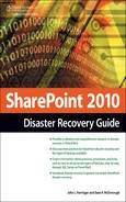
Open the Server Manager if it is not already open, and click on the Features item in the left menu. The Network Load Balancing Feature should be enabled on the server, as shown in Figure 6.1. If it is not enabled, add the Network Load Balancing Feature to the server before continuing.
Click the Start button and navigate to All Programs, Administrative Tools, Network Load Balancing Manager.
This opens the Network Load Balancing Manager application, as shown in Figure 6.2.
From the Cluster menu, select the New option to open the New Cluster : Connect window (see Figure 6.3) and create a new NLB cluster.
When the New Cluster : Connect window opens, enter the IP address and subnet mask for the first host to be added to the cluster, and click the Connect button. The NLB Manager searches for the server based on the IP address entered, and if found displays the names and IP addresses of any NICs on the target server that are available to be added to the new cluster in the Interfaces Available for Configuring a New Cluster list. Select the row for the NIC to be added to the cluster in the list, and click the Next button to continue. Figure 6.3 depicts the New Cluster : Connect window after a host to be added to the cluster has been located and a NIC on the server has been selected.
Caution
In a Multicast configuration such as the one this process describes, you should leave at least one of a server’s NICs out of the NLB cluster. This NIC is needed to enable traffic to directly reach the server on its own unique address; adding it to the cluster would not permit the Multicast configuration to function properly.
When the New Cluster : Host Parameters window opens (see Figure 6.4), if you want to add additional host IP addresses to the cluster, click the Add button to open the Add IP Address window (shown in Figure 6.5). In this window, enter the required information for the server’s dedicated IP address, and click the OK button. You can enter IP addresses in IPv4 format, or IPv6 format as long as your network is set up to use that implementation of the Internet Protocol. (If it is not set up for IPv6, this option is disabled.) After entering the dedicated IP address for the server, click the Next button to continue. If you want, you can continue without adding additional IP addresses. If you want to have multiple hosts participating in this cluster, though, you must add them in this dialog box.
The New Cluster : Cluster IP Addresses window is now opened, as shown in Figure 6.6. IP addresses added in this window are the target addresses that client computers use to access your SharePoint sites that are then load-balanced between the hosts in the NLB cluster. The IP address you enter here is the shared address that you should direct your users to use to access your load-balanced SharePoint site; the cluster takes the traffic to this IP address and redirects it to individual server nodes within the cluster. To add an IP address, click the Add button to open the Add IP Address window (identical to the Add IP Address window shown for Host IP Addresses in Figure 6.5). In this window, enter the required information for the clustered IP address, and click the OK button. The IP address entered must be a static IP address; NLB disables the Dynamic Host Configuration Protocol (DHCP) settings on each NIC it configures, which is why static IP addresses are required. You can enter IP addresses in IPv4 format, or IPv6 format as long as your network is set up to use that implementation of the Internet Protocol. (If it is not set up for IPv6, this option is disabled.) After entering the IP address for the cluster, click the Next button to continue.
The New Cluster : Cluster Parameters window opens, as shown in Figure 6.7, allowing you to configure the shared Uhostname for the new cluster you are creating and select the cluster’s operation mode. Enter the host name for the load-balanced host name of your SharePoint sites in the Full Internet Name text field; select the radio button for the desired cluster operation mode, which in this case is Multicast; and then click the Next button to continue.
The New Cluster : Port Rules window is now opened, as shown in Figure 6.8. By default, a single rule has already been created to encompass every TCP and UDP port on the clustered IP address. If you want to modify that rule, click the Edit button to open the Add/Edit Port Rule window (shown in Figure 6.9). In this window, you can apply the rule to the entire cluster or a single IP address if there are multiple in the cluster, change the range of ports included in the cluster for the IP address, select the Internet Protocol that the cluster uses, set its Filtering Mode, set its Affinity, or disable the selected range of ports for the cluster. To accept the defaults for the rule, click the Finish button to initiate the configuration of the cluster.
Note
An NLB cluster’s Affinity setting configures how “sticky” a session is between a client and a host within the cluster. If None is selected for a cluster’s Affinity, each client session is directed by the load balancer to the next available host in the cluster, regardless of whether the client previously was communicating with a specific host. Selecting Single sets a client to always be directed to the same host within a given session, regardless of its traffic load. The Network option directs requests from the same TCP/IP Class C address range, such as clients using multiple proxy servers to access the cluster, to a specific host in the cluster. For more information about NLB Affinity settings and SharePoint, see the “Windows NLB and SharePoint” section later in this chapter.
When the cluster configuration operation completes, the cluster is shown in the Network Load Balancing Manager screen in the left window pane under the Network Load Balancing Clusters entry (see Figure 6.10). To add hosts to the cluster, right-click on the new cluster’s name and select the Host Properties option from the menu. This opens the Host Properties window for the cluster (see Figure 6.11), allowing you to complete step 7 to add subsequent hosts to the cluster.


When implementing Windows NLB with SharePoint, you need to keep in mind and consider two main issues: operational mode and session affinity. You can configure each of these items in different ways, and your choices can have a definite impact on the functionality and performance of your SharePoint environment.
You are most likely to decide between Unicast and Multicast based on the configuration of your environment’s networking hardware. If your servers in the NLB cluster are configured with multiple NICs and flooding your switches is not an issue, Unicast is the best-fitting operational mode. If your servers have only one NIC or switch flooding impacts the performance of your network, Multicast makes the most sense. If you are building your servers from the ground up, the recommended approach is to install more than one NIC and go with Unicast, but these recommendations are based on general situations, and your specific requirements and environment may dictate otherwise. Regardless of the operational mode you select, make sure to apply this setting uniformly across all servers in the NLB cluster; each node must use the same setting, or you’ll encounter errors.
Note
If you use Multicast in your cluster, make sure that your network’s hardware is compatible. Specifically, your hardware must be able to accept the Address Resolution Protocol (ARP) replies generated by the multicast nodes in the NLB cluster or allow administrators to create a static ARP entry to properly resolve the addresses that the cluster is using. Although most modern networking hardware is now compatible with the functionality and settings required to make NLB work, you may still encounter legacy or niche hardware that is not compatible. You need to confirm that your infrastructure meets the needs of your solution and thoroughly test the full configuration before using it in a production environment.
Internet traffic, by design, is intended to be stateless. That is, each transaction between a client and a server is supposed to be self-contained and unconnected so that it can be routed by the most efficient means possible regardless of how communication operated in the past. Some SharePoint sites, such as public-facing sites using SharePoint’s Web content management functionality, are truly stateless, and each host within an NLB cluster should be set to None to take advantage of that stateless nature and focus on using the cluster to improve performance and stability.
But the reality of the situation is that not all traffic over a network, even a big network like the Internet, is stateless. And, although SharePoint is in many ways a typical stateless Internet application, this is not always the case. Some functionality, such as workflows or InfoPath forms, is prone to errors in load-balanced SharePoint environments where clients can communicate with any WFE server at any point in time. To avoid these errors and place a greater emphasis on data integrity, each node in your NLB cluster should have Affinity set at Single so a client’s repeated traffic becomes “sticky” by being directed back to the same WFE server for each trip. This ensures continuity in these transactions that do require the persistence of state for proper operation.
The most obvious advantage of using Windows NLB is cost. Because SharePoint requires the Windows Server operating system, you already obtained the right to use NLB when you purchased your Windows Server licenses. NLB does not require the additional purchase of expensive, proprietary hardware to enable HA for serving up your SharePoint content. Windows NLB also allows administrators to manage the NLB configuration by logging into your SharePoint servers, providing a central location for the administration of your environment’s critical platforms.
Windows NLB is not a sophisticated load-balancing solution. It can require specific or at times unusual networking hardware to function effectively. Its network bandwidth requirements make it a poor choice for load balancing across diverse locations for geographic redundancy. For a single NLB cluster to be spread across two datacenters, the connection speed between those datacenters must have response times of 500 milliseconds or less, a capability that could be difficult over extremely long distances and in certain wide area network (WAN) situations. (Your network must be capable of supporting a subnet that can span across a WAN connection.) Another possible solution for multiple sites is to create a separate NLB cluster in each location and direct traffic to one or the other via a Domain Name Services (DNS) round robin solution, but this approach does not truly distribute traffic loads between the sites.
Perhaps NLB’s biggest drawback is its inability to detect when a host within a cluster is no longer serving live content. If the IIS Web server in one of your SharePoint WFEs has crashed and is no longer sending Web pages to requesting clients, the NLB cluster continues to direct traffic to the Web server until its service is restored or the host is manually removed from the cluster. This can have a definite impact on your environment, because some end users are going to see intermittent errors while that downed server is still being used by the cluster—and that can be difficult to troubleshoot. It also requires manual intervention by an administrator, not only to remove the affected server from the cluster, but to determine which server is displaying the errors in the first place. Differentiating between load-balanced servers can be difficult when each is generating the same content, adding additional challenges to your ability to provide stable and consistent service via NLB.
Hardware load balancers are specialized networking applications designed to route traffic to certain individual servers in a network. You can configure hardware load balancers to distribute network traffic across multiple servers based on a variety of conditions such as connection volume, bandwidth utilization, processor utilization, and overall server performance. Software load balancers add an additional task load to the servers in the cluster on top of their normal tasks, such as generating the load-balanced content. Hardware load balancers, on the other hand, are specialized hardware devices whose sole responsibility is distributing traffic to their constituent servers according to their configuration. They are designed, engineered, and tested to efficiently and flexibly spread network traffic across the servers clustered beneath them.
The most obvious benefit to the use of a hardware load balancer is the reduction of workload on your servers compared to Windows NLB. Because the servers are not responsible for establishing and managing the NLB cluster, those free cycles can be allocated to other responsibilities, such as generating and serving content. Hardware load balancers also offer a variety of configuration and management options, although options do vary from manufacturer to manufacturer. Traffic destinations can be determined by affinity, server workload, bandwidth availability, geographic location, and several other factors. Clusters can span network subnets or even datacenters. Servers can be automatically or manually removed from active service depending on a range of criteria such as failure to respond or errors being displayed in requested content. Hardware load balancers are offered by several network hardware vendors, including Cisco, F5, Juniper, Coyote Point Systems, Barracuda Networks, and many more. Each vendor has its own feature sets, capabilities, and limitations. You should work with your organization’s network administrator(s) to determine the hardware solution that is the best fit for your needs if you decide to use a hardware load balancer.
Much like Windows NLB, hardware load-balancing is going to be most effective for a Share-Point farm when its affinity settings are configured to meet the farm’s most prevalent usage pattern, such as making sessions sticky when data needs to be maintained across server calls or stateless when transactions are anonymous. This is a universal requirement that should be tested and implemented (when testing shows that it is beneficial) whenever possible. One difference between hardware load balancers and Windows NLB is that the Unicast/Multicast operating modes are functions unique to NLB; there may be hardware solutions that offer similar functionality or drawbacks. You should review their documentation and conduct your own testing to determine the behavior of that functionality.
SharePoint is supported on most, if not all, hardware load-balancing solutions, so it is ultimately up to you and your network administrators to determine which solution is right for you. When evaluating a hardware load balancer, do not make your choice simply based on the load-balancing functionality of the devices. Also consider each candidate’s manageability and flexibility, because networking administration (especially for Web server-based solutions like SharePoint) is a fluid and ever-changing responsibility. Your hardware load balancer should be able to quickly enable configuration changes, effectively identify status changes in the servers beneath it, and make your life as a SharePoint administrator easier, not harder.
As SharePoint’s sales and popularity have grown, so has the need to deliver it to end users efficiently and consistently. This has not gone unnoticed by the manufacturers of hardware load balancers; several have begun to provide information, guidance, and configurations specifically geared toward the load balancing of SharePoint content with their products. This is great news for SharePoint administrators, because it means that the manufacturers have taken care of the extensive testing and monitoring activities necessary to find the configuration sweet spot for running SharePoint behind their devices. This allows you to quickly and often drastically improve the performance of your SharePoint environment with reduced risk to your service quality.
You should still exercise caution when considering a hardware load-balancing device optimized for SharePoint, because the gains in stability and functionality offered by these products can vary drastically depending on the configuration of your SharePoint environment and its network. If your SharePoint servers and the client workstations accessing your SharePoint site have high-bandwidth connections, you may not see performance gains worth the cost of implementing a SharePoint-optimized load balancer. This is because many manufacturers have focused on situations where network configurations lead to smaller or slower pipes for data to flow through, such as WAN connections. Connection speeds for WANs, which often use public communication links to connect local area networks (LANs) across multiple geographic locations, can pale in comparison to LANs.
It is easy to understand, given the connection limitations WANs face and the amount of network traffic that an active SharePoint site can generate, why this is a main area of focus for manufacturers. But if your network does not use or include WAN connections, you may not see large performance gains when using a SharePoint-optimized load-balancing device. Does this mean you shouldn’t use such a device in your network? Not at all. It’s just that you need to evaluate the reasons and requirements for load-balancing devices, along with the possible avenues of growth your network might follow, and select your resources accordingly. If your environment is not likely to include WAN connections and there is a more affordable device available that offers all the load-balancing capabilities you need, it is probably a better choice than an expensive purchase for technology that you are not going to see much benefit from.
Because hardware load balancers usually run on computing devices specifically devoted to providing load-balancing capabilities to a network, they are generally more stable and reliable than NLB. NLB has to run on your SharePoint WFE servers, so it is using computing resources that are tasked with a variety of functions. This in turn can lead to contention and impact the performance of an NLB cluster. But because hardware load balancers do not face the same competition for resources, they are more stable and offer better performance.
Hardware load balancers also offer a much wider range of functionality and features than what’s available in NLB. Depending on what the manufacturer of a specific device decides to include in it, you may have options for securing, compressing, or caching traffic sent through the device, not present in NLB. Also, hardware load balancers often can better identify and respond to errors, such as routing traffic away from failed nodes without an outage, or enabling a predetermined static error page should all of a cluster’s nodes become unavailable.
Just as cost is an advantage for NLB, the high cost of purchasing specialized hardware is a definite drawback for hardware load balancing. The good news is that this is a diverse marketplace with offerings filling a broad range of price points, and feature sets to match those costs. For some budget-minded organizations, it might be awfully difficult to get away from a comparison of potentially high costs against NLB’s price tag of $0.00.
Adding a hardware load balancer to your environment also means that you need to integrate yet another component from yet another manufacturer into your environment, adding to its overall complexity and making it more difficult to manage. Manufacturers often implement unique, proprietary hardware components and setups to add to their ability to differentiate their products and lock customers into their solutions. These dependencies can make it more difficult to manage your SharePoint environment in general, not to mention your HA solutions in particular.
Finally, not all hardware load-balancing options offer the advanced error detection and handling capabilities mentioned earlier, which means your environment could face the same kind of risks NLB clusters do because they lack this functionality. Regardless of the load-balancing solution you choose, make certain that you understand exactly what it can and cannot do; optimally, you’ll be able to mitigate those risks via other tools or procedures, but at a minimum you need to be aware of what they are.
Implementing load balancing to distribute traffic across multiple resources within your Share-Point farm can positively impact the performance of your servers and, most importantly, the end user experience. It can also ensure that your environment can withstand the loss of a server within the farm by sharing the load between multiple resources. But you don’t achieve that benefit simply by adding more servers to your environment, installing SharePoint on them, and adding them to an NLB cluster. You need to understand not only the areas within your Share-Point farm where load balancing can be advantageous, but where it provides little to no value and where it can actually be detrimental to the health of your system. Not only that, but Share-Point 2010 introduces a new approach to scalability with the Service Application model (which replaces the SharePoint 2007 concept of Shared Service Providers, or SSPs); allowing you to architect a much more highly available solution for your entire SharePoint environment, not just your Web servers or SQL Server instances.
The most obvious item within your farm that benefits from load balancing is the WFE role, which is responsible for serving SharePoint’s Web pages, content, and functionality to your end users. If you have a large user base who frequently visit your SharePoint sites or you need to make sure that your content is always online and available, you will most certainly want to load-balance your WFEs.
One interesting thing that Microsoft discovered in SharePoint 2007 about load-balancing WFE servers is that there is a point where the performance of your environment flattens as you insert additional WFEs to scale out the farm. Microsoft conducted extensive testing of how SharePoint 2007 performs under extremely heavy loads, for a variety of typical use cases. Although Microsoft has made a great deal of information about the product available well ahead of its release, the problem with SharePoint 2010 being such a new product is that there just has not been enough time to do the same kind of capacity performance testing with the final version of the product.
To its credit, Microsoft has been working to deliver this content with the launch of SharePoint 2010, but it is not fully released for all of SharePoint’s numerous use cases. At the time this book is being written, Microsoft has released case and lab studies that examine the performance metrics of large-scale SharePoint environments focused on collaborative activities, SharePoint’s most common use. Much as in SharePoint 2007, these studies show that in a SharePoint 2010 collaborative environment, there is a definitive point where performance gains flatten out as new WFEs are added to a load-balanced farm. The flattening tends to occur when a fourth WFE is added to a farm. After that point, there was no value in adding additional WFEs. Beyond the fourth WFE, performance was being constrained by CPU utilization on the SQL Server instance hosting SharePoint’s databases, not SharePoint itself. If you would like more information on Microsoft’s testing approach and findings with SharePoint 2010’s capacity and performance limitations, head to the Capacity Management for SharePoint Server 2010 Resource Center on TechNet, at http://technet.microsoft.com/en-us/sharepoint/ff601870.aspx. It is an outstanding repository that is sure to have new content on the subject of SharePoint 2010 capacity planning added on a regular basis and well worth a look.
If you are planning a large implementation of SharePoint, test your configuration on its own so that you can determine your performance baseline and whether it’s going to meet your needs. Performance may vary depending on a variety of factors, as follows:
Network configuration. The unique configuration of your network and its hardware may provide you with performance metrics that vastly differ from Microsoft’s.
Hardware configuration. The unique configuration of your server hardware may also provide you with performance metrics that vastly differ from Microsoft’s.
Caching configuration. Configuring your farm’s servers and content to leverage caching functionality can drastically improve the performance of your Web servers.
Farm usage scenarios. A farm intended for internal collaboration and knowledge sharing by authenticated users is going to perform differently from a farm intended for Web content management and anonymous users.
Because load balancing is common for SharePoint to improve performance, Microsoft has made the process to add additional servers to a SharePoint farm easy and straightforward. The SharePoint installer should be run on the server to be added to the farm, using the same accounts and configuration as the rest of the servers in the farm, making sure to do a Complete Advanced installation. Once the installer finishes, the SharePoint Products and Technologies Configuration Wizard starts up. Walk through the wizard, making sure to select the Connect to an Existing Farm option, and then connect to the configuration database for the existing farm. Confirm that the server is not set to host the farm’s Central Administration site (unless you have a specific requirement to create a redundant site), and complete the wizard. Log into the Central Administration site, and configure the server with the WFE role that it should play in the farm.
Note
Adding a server to a farm within SharePoint does not automatically add it to the pool of load-balanced servers for Windows NLB. You must still perform this configuration step in the management tools for the load-balanced cluster, not in SharePoint, for end users to reach the server via the load-balanced URL.
In Microsoft Office SharePoint Server (MOSS) 2007, Microsoft introduced the concept of SSPs, applications within a farm designed to provide specialized services—such as My Sites, Search, and User Profiles—to multiple Web applications within the farm. SSPs were helpful in that they allowed common functionality to be used consistently across sites and Web applications in the farm, but the approach was not without its drawbacks. SSPs were often difficult to manage, especially in large farms, and they were a challenge to protect from a DR standpoint. In the case of Search specifically, SSPs represented a single point of failure because only a single server could be designated for operation in the Index Server role for a given SharePoint Search index.
Microsoft has revamped its approach to these types of applications in SharePoint 2010 by retiring the concept of an SSP and introducing the Service Application model. It also applies to both SharePoint Foundation 2010 and SharePoint Server 2010 instead of just the server product. Microsoft has designed the Service Application model to build on the direction taken by the SSP approach while addressing some of its shortcoming and drawbacks. Service Applications are designed to provide scalability to your SharePoint farm, give administrators greater control over which services are delivered to SharePoint resources, and allow third-party vendors to create their own custom Service Applications to enhance and extend the functionality available through a SharePoint environment.
The big reason that Microsoft’s change from SharePoint 2007’s SSP model to SharePoint 2010’s Service Application model makes such a difference is in how it handles load. With SharePoint 2007, applications within the SSP were often difficult to scale out as usage increased. Some applications, such as Excel Services, required careful consideration and configuration to set up for large environments or high availability. Search in SharePoint 2007 was an even more frustrating story: the Index server role could not be spread across multiple servers, making it a single point of failure.
In a multiserver SharePoint 2010 farm, Microsoft recommends that Service Applications are hosted on dedicated application servers (giving the farm a three-tier hierarchy, with the other tiers consisting of WFEs and SQL Server hosts). These application servers host the Service Applications and respond to requests made by the client applications hosted by the farm’s WFEs to deliver their functionality. If the farm has multiple application servers, it is not necessary to configure a load-balanced cluster (via NLB or a hardware load balancer) as it would be for a farm with multiple WFEs. Instead, Microsoft has built a simple round-robin load balancer into its Service Application Framework that distributes traffic across each application server automatically.
The one piece of SharePoint most impacted by the new Service Application model in SharePoint Server 2010 is Search. SharePoint’s Search capabilities have always been a highly touted aspect of the platform, and that’s no different in 2010, featuring lots of new features and functionality for end users. But with this new release also comes a much better story around the idea of making SharePoint’s Search infrastructure pieces highly available. This simply wasn’t possible in MOSS 2007 due to the inflexible nature of the Index server role, but SharePoint Server 2010 gives you a great deal of flexibility and scalability.
Note
The content in this section focuses almost entirely on the Search functionality of SharePoint Server 2010. Although SharePoint Foundation 2010 does now allow for the presence of multiple Search servers within a farm, those servers cannot be deployed redundantly. Each Search server must be configured to crawl and index different content databases within the farm, so you cannot configure the farm so that if one Search server goes down its load is distributed to the other servers. If one Search server goes down, its indexed content is unavailable. There are also three other search products related to or for SharePoint 2010 from Microsoft: Search Server Express 2010, Search Server 2010, and FAST Search Server 2010 for SharePoint. These products may be worth your consideration, but this book focuses on covering and protecting SharePoint’s core functionality. Please review the documentation for the products mentioned to determine if and how they can be made highly available.
SharePoint servers in a farm can serve a few different roles to add performance and functionality to the farm’s search capabilities. The two listed server roles affiliated with searching in a Share-Point farm are the Crawl server role (known as the Index server in MOSS 2007) and the Query server role. Crawl servers are responsible for generating the farm’s search index by crawling the target content sources and building the index with the results of that crawl. Query servers are tasked with the processing required to execute all requested queries against a copy of the farm’s search index stored locally on the Query server. In SharePoint 2010, you can assign both the Crawl server and Query server roles to multiple servers within a farm, allowing for redundancy and load distribution of SharePoint’s Search functionality.
A Crawl server must be associated with a single Crawl database; this database specifies the content that the Crawl server must crawl to build its assigned index. This relationship allows for Search indexing to be constructed for both redundancy and scalability, as desired. You can add redundancy to a farm’s Search crawls by associating multiple Crawl servers with a single Crawl database so that if one Crawl server becomes unavailable, a replacement is available to continue indexing the Crawl database’s designated content. If you want to improve the performance of the crawl activities, you can create additional crawl databases. This allows you to separate the crawl content between databases so that multiple Crawl servers can process and crawl it in parallel.
Query servers respond to search queries submitted by end users on WFE servers and return results using the Search index generated by the farm’s Crawl servers. If a single server in the farm is configured with the Query role, a copy of the entire index is stored in the Query server’s file system. If a farm has multiple Query servers, each Query server receives an index partition, or a portion of the overall index. By default, the distribution of index partitions is based on the number of Query servers in a farm, but administrators can manually specify the number of index partitions that are created and how they are distributed. In the case of two Query servers, for example, each server stores an index partition equal to half the index. If there are four Query servers, each server stores an index partition containing 25 percent of the overall index. This approach allows for redundancy (if one of many Query servers in a farm goes down, the index partitions can be redistributed to cover the outage) and may improve performance as additional Query servers are added to a farm.
Caution
Although the new Search architecture in SharePoint Server 2010 overcomes a number of the problems administrators faced with redundancy and scalability in MOSS 2007, it still has components that you can’t duplicate within a farm. Each farm requires a Search Administration component that can only be deployed to one Crawl server in a farm, and only one Search Administration database can be associated with that single Search Administration component. The database can only be made redundant if database mirroring or clustering is implemented (see Chapter 8, “SQL Server 2008 High Availability” for more information); the Search Administration component itself cannot be made redundant. The impact of losing these pieces would be minimal and mainly affect an administrator’s ability to manage the Search functionality; the farm’s Search service would still be available but could not be modified.
This new Search architecture also allows for entire SharePoint Server 2010 farms dedicated to crawling content and responding to search queries. This is typically only a consideration in large, often global, SharePoint deployments, but it does add versatility in search scenarios that were often troublesome in MOSS 2007.
Load balancing your Web servers is by far the most obvious and effective way to ensure continuous uptime for your SharePoint environment, but it does not necessarily represent a complete HA solution. Because SharePoint requires such a wide range of infrastructure and systems to function, you need to configure these systems redundantly so they can be as highly available as your load-balanced SharePoint components. The failure of a hard drive or network connection can just as easily impact SharePoint’s service levels as the more obvious candidates for HA, SharePoint, and SQL Server. Luckily, the IT industry has been hard at work for years to develop and create stable, redundant infrastructure components that address those problems.
Let’s face it: it’s impossible to have a server running Windows Server 2008 and not have some sort of storage device attached to it. Hard disk drives, commonly known as hard drives, have been used in computers for more than 50 years and have evolved and improved as much as processors have over the years, albeit with much less fanfare. Modern hard drives are designed not only to store large amounts of data (manufacturers are now producing drives with capacities measured in terabytes), but to make reading, writing, and transmission of that data happen as quickly as possible. But one thing hasn’t changed: drives still fail.
That is not to say that manufacturers have ignored the reliability of their products. That statement could not be further from the truth. Today’s hard drives are made to last longer while still withstanding the heavier workloads that interconnected, data-driven computer systems place upon them. They are being made to use less power and reduce noise and to handle sudden movements such as those that could impact the hard drive of a laptop computer. But real-world experience has shown that hard drives are still prone to failure for a variety of reasons.
To expect otherwise is foolhardy, if not irresponsible. Want proof? Consider the findings offered by Google, probably one of the largest consumers of hard drives in the world. In a white paper published in February 2007 (http://labs.google.com/papers/disk_failures.pdf), Google presented data based on analysis of hundreds of thousands of hard drives. It found that, despite the best efforts of manufacturers and system administrators, hard drives are prone to failures caused by a variety of sources, especially as the drives become older. Age is not the only reason for hard drive breakdown, and Google is careful to point out that it should not be the only determining factor. But it’s important to keep in mind that as a drive gets older, it is more likely to fail.
When it comes to the business-critical data stored on your servers and in your SharePoint environment, we recommend that as a part of an effective disaster recovery plan, you should not only back up your data on a regular basis, you should also configure the systems you store that data on as redundantly as possible. This helps to make certain that your data is still available if a hard drive fails, and it avoids any outages that may be experienced while a backup is being retrieved from storage and restored. The good news is that modern IT systems have some effective solutions available to them to redundantly store their data.
A Redundant Array of Independent (or Inexpensive) Disks, more commonly known as a RAID array, is a storage solution that uses two or more actual hard drives to create a reliable storage option for servers. The multiple disks in a RAID array are configured to be presented to a server as a single device, providing a redundant solution that can either copy or distribute data across the disks in the array.
Note
Because there are so many hardware vendors and configurations for RAID arrays on the market today, be sure to review any documented performance metrics for your RAID solution, and if possible do your own testing, to better understand how quickly it can do the various types of disk operations you plan to use it for. As shown next, in general, different RAID configurations work best for different types of operations, but technological and design advances may prove differently for specific products.
There are several types of RAID arrays, each providing different attributes and drawbacks to be considered. Some of the most common are listed here:
RAID 0. With RAID 0, data is “striped,” or broken down into blocks, and each block is written to different disks in the array. RAID 0 requires at least two hard disks to implement, and its primary advantage is its ability to read and write data to the disk much more quickly than a single disk. Because data is not duplicated across multiple disks in the array, RAID 0 does not provide fault tolerance for high availability.
RAID 1. In this configuration, data is “mirrored” across each disk in the array so that it is preserved if a drive in the array fails. Writing to the array takes slightly longer than a single disk, because the array is writing to multiple drives (a problem more often seen in software-based RAID solutions than in hardware-based ones). The available storage in the array is also limited to the size of the smallest disk in the array.
RAID 5. This combines a minimum of three disks and ensures that the data on one disk in the array is duplicated on at least one of the other disks in the array. It provides fault tolerance (it can withstand the loss of one disk in the array), and reading data from a RAID 5 is similar in performance to a RAID 0. Writing to a RAID 5 array is a different story, because it generally takes considerably more time to determine what should be written and where it should be written within the array. The total storage capacity of a RAID 5 array is the sum of all disks in the array but one.
RAID 6. This is similar in configuration to RAID 5, but it offers additional fault tolerance, allowing the array to survive the loss of two disks in the array. Read performance is equal to that of RAID 5, but writes can take even longer. The total storage capacity of a RAID 6 array is the sum of all disks in the array but two.
RAID 10 (also known as RAID 1+0). RAID 10 is a combination of RAID 1 and RAID 0. With RAID 1+0, drives in the array are paired, data is mirrored across the pairs, and the data is striped throughout the array. RAID 1+0 can also experience the loss of up to 50 percent of the drives in the array and still maintain data integrity. RAID 1+0 offers faster read and write operations than RAID 5.
Beyond the configuration of the RAID array, there are two ways to implement an array: software and hardware.
Software RAID. Some operating systems, including Windows Server 2008, can create RAID arrays by creating logical disks that are then mapped to the physical disks attached to the server. Using a software RAID configuration can reduce costs, but managing the array can impact a server’s performance—particularly in the case of computationally expensive RAID configurations, such as RAID 5. More importantly, manual intervention is required to fail over the array if there is a hard disk failure within the array, leading to service outages.
Hardware RAID. Hardware RAID controllers are specifically built to manage and operate RAID arrays and can be implemented as expansion cards installed in the server or built into the server’s motherboard. They offer numerous advantages over software solutions, such as no use of a server’s processing power, onboard caching, better failover options, and better error handling, but they can be expensive.
It’s difficult to advocate a specific RAID array configuration for your SharePoint farm, because everyone’s requirements, budget, and infrastructure are unique, and these factors influence the decision. Because server roles within a farm use their hard drives in various ways, you may end up with different RAID array configurations within your farm. If your organization has a standard configuration for RAID arrays in its datacenters, review those settings to confirm that they meet your requirements. The list that follows outlines several items you should keep in mind when designing your RAID configurations.
Use hardware RAID controllers when possible. Hardware RAID controllers offer so many advantages over software-based controllers, especially where RAID is being used to ensure fault tolerance in disaster recovery solutions. They are more expensive to implement, but they may prove to be worth the investment if they end up saving you big bucks by avoiding productivity-killing downtime for your SharePoint environment.
Right-size solutions for WFEs. WFEs do not necessarily need big-time RAID 1+0 arrays to store their data. In most situations, RAID 1 or RAID 5 is sufficient to provide data preservation and fault tolerance in case of a failure, because SharePoint WFEs do not read or write as much data from and to their disks as SQL Server 2008 does.
Right-size solutions for SQL Server 2008. As you will see in Chapter 7, “SQL Server 2008 Backup and Restore,” SharePoint’s SQL Server databases mean everything to the farm’s survival. Moreover, SharePoint is pretty hard on its databases, performing countless reads, writes, and deletes to them every second under load. It makes sense to use the most fault-tolerant, high-performing array configuration you can afford for the hard drives of your SQL Server.
Use quality hard drives. An easy way to ensure good performance for your RAID arrays is to use hard drives with fast access times and large amounts of cache memory built in.
Use enough hard drives. Adding disks to your arrays is another easy way to improve RAID performance. This gives the array another drive to store content on, provides additional redundancy within the array, and can increase the available disk space (depending on the array configuration).
The other storage option available (besides just using hard drives in your servers) that makes sense to use with SharePoint is storage area networks, or SANs. SANs let you attach remotely located storage to a server so that the operating system displays and treats the storage as if it were local. SANs are usually best suited to large enterprises due to their high costs to implement, but smaller organizations can also purchase managed SAN storage products from hosting providers if desired.
SANs can be a viable disaster recovery solution based on their ability to make storage resources available to servers in multiple locations. SANs are also a good way to make large amounts of storage available in a configurable fashion; this makes them appealing as a storage location for SharePoint’s SQL Server databases. As Chapter 8 explains, SAN storage is also required to enable Windows failover clustering, a tool that can be important in making SQL Server 2008 highly available.
Although SharePoint’s SQL Server databases definitely lend themselves to being stored in a SAN, most of SharePoint’s additional storage needs do not map particularly well to a SAN solution. In most cases, the benefits of a SAN are outweighed by the high cost of using such a resource for the relatively small-in-comparison hard drives of a SharePoint server, especially when there are other ways that the data stored there can be backed up or made highly available.
In addition to some of the hardware considerations for storage that you need to be aware of, keep in mind that the server operating system that you run SharePoint 2010 on may also be able to do some new things to help make your systems more highly available. Windows Server 2008 now offers several features not found in Windows Server 2003 that can help keep your server’s storage healthy and functioning properly, such as these:
Self-healing NTFS. Prior to Windows Server 2008, if a Microsoft server OS detected corruption in the file system of a New Technology File System (NTFS) storage volume (the most commonly used format for drives attached to computers running Microsoft operating systems), the volume had to be taken offline to correct the errors that had been found. With Windows Server 2008, the operating system is able to run a process in the background to repair and isolate damaged regions without taking the full storage volume offline.
S.M.A.R.T error detection. The Self-Monitoring, Analysis, and Reporting Technology (S.M.A.R.T.) monitoring system for computer disks has been around for a while in monitoring systems like Microsoft System Center Operations Manager 2007 (SCOM), but Windows Server 2008 is the first time that S.M.A.R.T. detection techniques are being used within a Microsoft server OS to identify and warn administrators of drive failures before they may arise.
Enhanced management of storage networks. Microsoft implemented the Internet Storage Naming Server (iSNS) protocol in Windows Server 2008, which allows the OS to manage disks attached via the Internet Small Computer System Interface (iSCSI) just as it would disks attached to the server via Fibre Channel (such as SANs). This makes management of those iSCSI devices much simpler and more effective.
Disk resizing on the fly. With Windows Server 2008, administrators can now resize hard disk partitions without shutting down the server hosting the partitions, even if the target partition is the system drive. Although this does not apply to striped drives (such as drives configured in a RAID-0 array), it does allow for greater flexibility when managing your servers’ storage.
In October 2009, Microsoft made available a second release of Windows Server 2008, known as Windows Server 2008 R2. (Microsoft is clever with its naming standards for this product, isn’t it?) This updated release contained a wide range of new features and functionality for Microsoft’s flagship server operation system, but not enough to warrant incrementing the product’s version number. The R2 release had two updates that were pertinent to server storage:
Storage fault tolerance. If a server running on Windows Server 2008 R2 has multiple paths connecting it to a storage device, the OS can switch to an alternate path to the device should the primary fail or become unavailable. The OS also allows for the configuration of the priorities for these paths to your storage device for better flexibility in configuration.
Storage configuration backups. Windows Server 2008 R2 allows administrators to take snapshots of their storage configuration settings, such as its iSCSI setup, so that the server can be quickly restored to a functioning state should the configuration fail or change unexpectedly and affect the availability of a server’s storage.
The most common element of SharePoint to make highly available via a clustering tool such as Windows failover clustering is its SQL Server databases. The topic of Windows failover clustering and SQL Server is covered extensively in Chapter 8.
The other element of your SharePoint environment that is vulnerable to hardware failures and outages is your networking hardware and infrastructure. If your network or a component within it should fail, is your environment redundant enough to keep lines of communication open between your users and your SharePoint farm? What about between your SharePoint farm and its database servers, domain controllers, and other crucial remote resources? Don’t overlook the vital components that provide the key lines of communication into and out of your environment when planning for high availability.
Work with your network administrator(s) to confirm that the switches, routers, load balancers, and other pieces of the network are redundant, so that the connection to the network remains active if one of those items should fail. Regularly test your network to confirm that communications are being quickly and efficiently routed from point A to point B, and to make sure that all address mappings and configurations are correct so that traffic can get to where it is supposed to.
Your servers can be configured with additional NICs, a setup that can offer a lot of additional benefit to your system. Not only do multiple NICs allow for the use of the Unicast operating mode with Windows NLB, but you can establish specific channels for communication, restricted to a specific IP subnet, between your SharePoint servers and their database instances. This is beneficial to performance, because it gives your farm a network location solely devoted to its own database traffic, the foundation of SharePoint’s publishing process. It also provides important security to the process by restricting access to the IP subnet to only the servers using it. Multiple NICs can also be teamed, opening up greater bandwidth into and out of your server for content to flow through, as well as making it possible to add greater redundancy and failover capabilities to your servers should a NIC fail.
As a SharePoint administrator, it is all too easy to become locked onto the SharePoint or SQL Server components of your environment. But from the perspective of disaster recovery and high availability, that just isn’t enough. SharePoint depends on many systems, devices, and processes to function effectively. As an administrator, it is your responsibility to make sure that those constituent items are just as robust, redundant, and available as your SharePoint systems are. How you are able to accomplish that depends a lot on the kind of operating budget you have available and your existing resources. The good news is that SharePoint and its constituent systems are pretty flexible, so you have flexibility and options. Oftentimes, the hard part is sifting through those options to determine which is best for you.
A point that we have consistently stressed throughout this book is the importance of testing and monitoring everything within your environment. It is far better to know ahead of time when a system is failing or needs repair or modification, because that way you have more time to plan the right solution and put it in place—not to mention that it’s a much easier conversation to have with your supervisor and customers than the alternative.
The concepts and information in this chapter are designed to get you thinking about the foundational systems of your SharePoint environment and what you can do to make them highly available. The best solution for you depends on your organization and its needs, but whether you have a single SharePoint Foundation 2010 server that is accessed by 10 users or a global organization with multiple SharePoint Server 2010 farms and thousands of users, implementing some, any, or all of the concepts in this chapter can only benefit your SharePoint environment.
After completing this chapter on Windows Server 2008 High Availability, you should be able to answer the following questions about their capabilities. You can find the answers to these questions in Appendix A, “Chapter Review Q&A,” found on the Cengage Learning Web site at http://www.courseptr.com/downloads.