Chapter 6: Building a Solid Sumobot
Sumobots and battlebots are both terms that you may have heard of before. In case you don't know what sumobots are, they are basically robots that are designed to battle one another. Basically, it is a sport where two robots battle in a head-to-head competition to outlast the other robot. Battle robots are a classic build challenge for any robot enthusiast. From the popular YouTube show that led to shows that are now on TV, Twitch, and other platforms, you can find robots battling on all types of arenas, designed from about every conceivable idea you can imagine. These robots come in all shapes and sizes, depending on the rules of the competition. These robot challenges are quite popular in schools, after-school programs, and summer camps when it comes to sumobots. The robot you will build in this chapter will provide you with a solid foundation for being dominant in your next arena battle.
Here is a picture of what your base sumobot will look like by the end of this chapter:

Figure 6.1 – Sumobot
In this chapter, you will break down the build and program as follows:
- Preparing the main frame
- Increasing the torque of wheels using gears
- Adding the sensors
- Building the back bumper
- Strengthening the frame with outside supports
- Programming the sumobot to stay in the arena
- Programming the sumobot to attack when the enemy is close
Technical requirements
To build the robot, all you will need is the Robot Inventor Kit. For programming, you will need the LEGO MINDSTORMS app/software.
You can find the code for this chapter at https://github.com/PacktPublishing/Smart-Robotics-with-LEGO-MINDSTORMS-Robot-Inventor/blob/main/Chapter%206%20Sumobot%20Code.lms.
If you would like a more detailed photo-by-photo build process of the robot, please head here to view the relevant images: https://bit.ly/30JaXvB.
Building the robot
Before we get into building this robot, let's explore the strategy we'll be using. There are a lot of strategies in the world of sumobot competitions, but for the sake of this chapter, you will stick with probably the most tried and tested methods to guarantee sumobot success. The design of this particular sumobot is based on the following strategies:
- The robot should be low to the ground with as little clearance space as possible from the ground to prevent it from being flipped over.
- The robot should be low in terms of height to keep its weight distribution and center of gravity low to the ground.
- Gears should be used to create more torque and power for the robot to push and keep it from being pushed around.
Keeping these three features in mind will help you understand why the robot is designed the way it is. Additionally, the robot has been designed in a way that it allows plenty of customization to be made to it, without us losing sight of these strategies.
Preparing the main frame
For this build, we will use the 11x17 teal plate to keep things sturdy and strong. By using this plate, along with the two large frames, we will begin to design a strong base for the robot to operate on.
To get started, you will need the following pieces:
- One teal 11x17 base plates
- Two black 11x15 open frames
- One black 7x11 open frames
- 19 black connector pins
- Two teal 3x3 Technic pieces
- Two brown 5L axles with stops
- Four blue connector pins
- Four teal 2x4 L beams
Begin with the base plate, three black connector pins, and two black 11x15 open frames:

Figure 6.2 – Floor of the robot
Bring the two open frames together using three black connector pins:

Figure 6.3 – Three black pins to connect the frames
Add another eight black connector pins to the open frames:
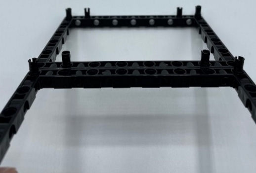
Figure 6.4 – Positions of the black connector pins
Using four more black connector pins, place one on each of the two teal 3x3 pieces and two to the teal 11x19 plate:
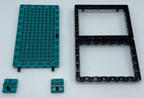
Figure 6.5 – Teal 3x3 pieces to be added to the base plate
These elements will provide additional support for what will become our back sliders for the robot to maneuver properly:
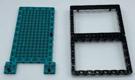
Figure 6.6 – Teal 3x3 slider supports
Once you have those 3x3 elements connected to the base plate, go ahead and add the open frames to the top of the teal base plate using the eight black connector pins you added to the open frames in the previous steps:
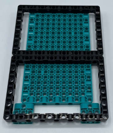
Figure 6.7 – Stack the open frame on the teal base plate
Use four more black connector pins and the two brown 5L axles and add them to the teal plate and 3x3 Technic pieces:
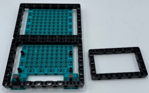
Figure 6.8 – Brown axles and pins added
Add the black 7x11 open frame to the pins you just installed on the teal plate:
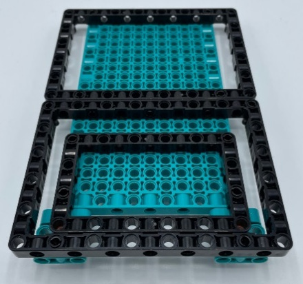
Figure 6.9 – 7x11 open frame added
Next, add four blue connector pins to the open frames:

Figure 6.10 – Blue connector pins added to the open frame
Go ahead and flip over and further secure the bottom by pushing in all the connector pins properly. This will prevent the robot from falling apart upon contact:
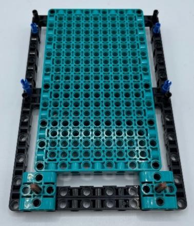
Figure 6.11 – Bottom side of robot
Now that your robot is flipped over, add the four teal 2x4 L beams to the pins that are available:
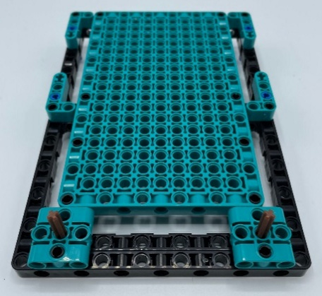
Figure 6.12 – L beams added to the pins
You should now see the brown axle. Here, you will add your sliders using the following pieces:
- Two smooth black wheels
- Two gray bush stops
These pieces will act as sliders to allow the robot to quickly pivot, spin, and move around the arena:
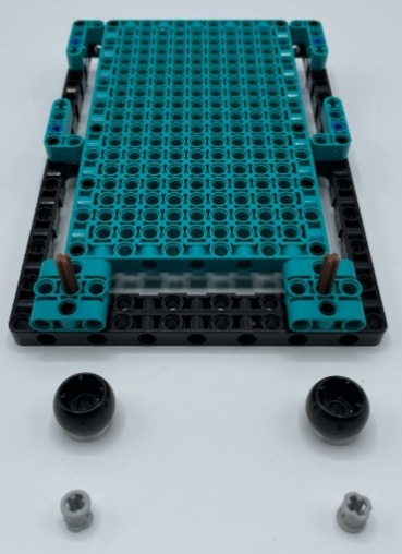
Figure 6.13 – Slider elements
Add the wheels to the brown axles and secure them in place using the gray bush stops:
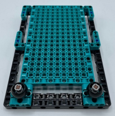
Figure 6.14 – Sliders complete
This section is complete. It is now time to add the Intelligent Hub and motors.
Increasing the torque of the robot's wheels using gears
Now that the bottom of the base is nearly complete, let's flip it back over and start adding the motors and Intelligent Hub to bring the robot to life.
To build out the motors and Intelligent Hub, you will need the following:
- One Intelligent Hub
- Two motors
- Two wire clips
- Two gray bush stops
- Two black 8L axles
- Two black 12-tooth double bevel gears
- Two red axle pins
- 12 black connector pins
To begin, you must push the black axles through the large black open frames. You will install one gray bush stop between the frame and end of the axle for spacing reasons. You must also add the black gears to each motor using the red axle pins:
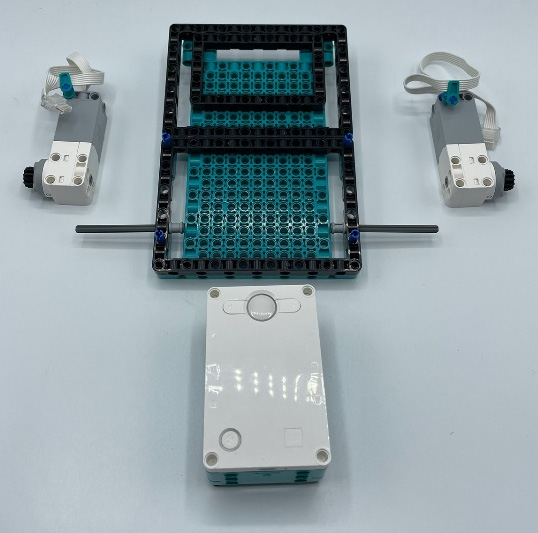
Figure 6.15 – Motors and Intelligent Hub
Next, install both motors to the outside of the frame using black connector pins. Use four for each motor using the four pin holes on the motor:
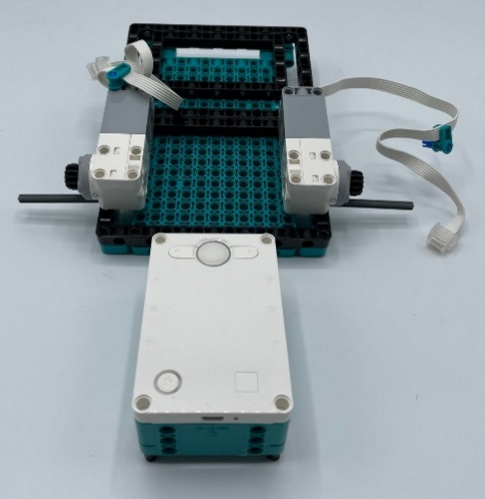
Figure 6.16 – Motors added to the base plate
Now, go ahead and add the Intelligent Hub by placing four black connector pins in each of the corners on the underside. Be sure to install the Intelligent Hub with the charger port pointing out to make it easier to charge and plug the Intelligent Hub into your computer:
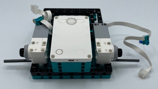
Figure 6.17 – Intelligent Hub added
Now is a good time to use the wire clips to organize your motor wires:

Figure 6.18 – Wire clips to organize wires
Our end goal with our motors is to create more torque. Remember that this robot's strategy is to create more power than our opponent. You are creating a robot that is gearing down and not gearing up. Torque is a measure of the force that can cause an object to rotate about an axis. In your case, you are gearing down. A small gear is spinning a larger gear, so it will take more spins of the smaller gear so get the larger gear to make one complete rotation.
The opposite is also true. If we were to place a large gear on the motor and then attach it to a smaller gear on the wheel, the robot will go much faster (see Chapter 7, Building a Dragster, for this example). The one rotation of the larger gear will cause the smaller gear to spin that much faster based on the ratio of the two gears, thus creating more speed.
For the sake of this robot, think of torque as the strength of the vehicle.
You will need the following parts to make this happen:
- Two large tires with rubber traction
- Four gray bush stops
- Two tan 20-tooth double bevel gears
- Two black round axle connector blocks
- Six black connector pins
The following image is a visual to help us see how the parts will go together:
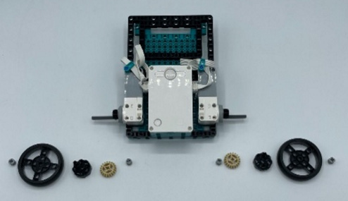
Figure 6.19 – Gearing pieces
The parts in the preceding image are laid out in the order in which they go onto the black axles of the robot. Follow these steps:
- Slide on a gray bush stop onto the black axle.
- Slide on the tan gear. This gear should align with the black gear on the motor.
- Add two black pins to the black round connector and slide them onto the black axle.
- Slide the tire onto the axle and connect it to the black round connector with the pins.
- Hold everything in place using another gray bush stop.
- Repeat this on the other wheel:
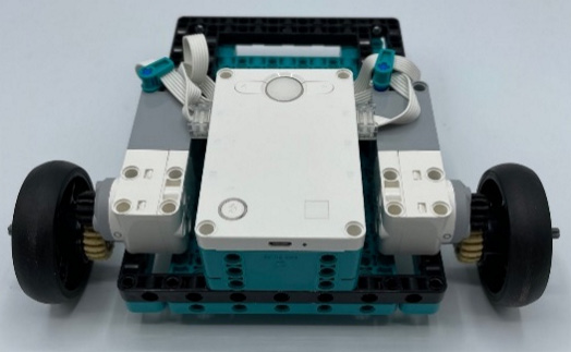
Figure 6.20 – Wheels complete
This is a very important time to check that everything is aligned and that the gears are connected. There might be some movement if you test the motors, which you will secure better once you've finished the outside frame of the robot. For now, you can test this robot and ensure it moves around okay. Sometimes, the gears can be a bit tight if you smashed the elements too tight. Run some quick tests to ensure things move properly.
If everything moves okay, then we can finish this section by adding two black connector pins to the Intelligent Hub on the top pin hole:
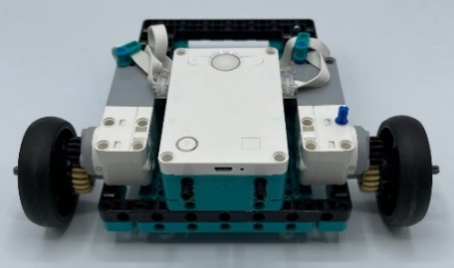
Figure 6.21 – Connector pins added to the Intelligent Hub
Note that one blue axle pin has been added to the right motor in the previous image. Add one now as you will use a wire clip to keep the wires organized from the sensors that you will eventually add.
Adding the sensors
Most sumo arenas are black with a white line painted along the edge of the circular arena. You will need the color sensor facing down to prevent your robot from driving off the edge and losing. The frame you have makes adding a color sensor very easy to do:

Figure 6.22 – Sumobot arena
You will need the following pieces to add a color sensor:
- One color sensor
- Two teal 3x3 Technic pieces
- Six black connector pins
Begin by adding three connector pins to each of the 3x3 Technic pieces. Add two to the back and one on the side. These pieces will connect to the sensor and then eventually connect to the robot:

Figure 6.23 – Teal pieces to frame the color sensor
Keeping the sensor facing down to the ground so that it can detect the edge of the arena, attach this piece to the front of the frame and Intelligent Hub:
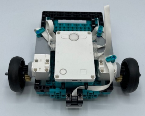
Figure 6.24 – Color sensor added to the front
Next, you must add the distance sensor to the front of the robot, right above the color sensor. You will need to build a mini attachment to make this work.
You will need the following pieces:
- One distance sensor
- One black 11L beam
- Two black connector pins
- One black 7x11 open frame
- Four gray connector pins with bush stops
- Two dark gray axle connector pins
- Two black round connectors
Begin this attachment by adding two black connector pins to a black 11L beam. Add them to the third pin hole from each edge:
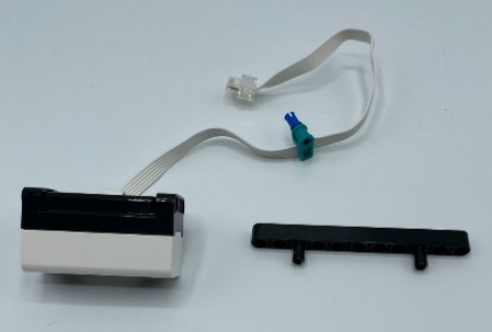
Figure 6.25 – Black beam for sensor support
Add this beam to the back of the distance sensor:
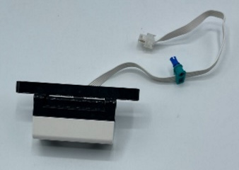
Figure 6.26 – Beam added to the back of the sensor
On each gray connector pin with a bush stop, add a dark gray axle connector pin. On each of the dark gray pins, slide on a black round connector:
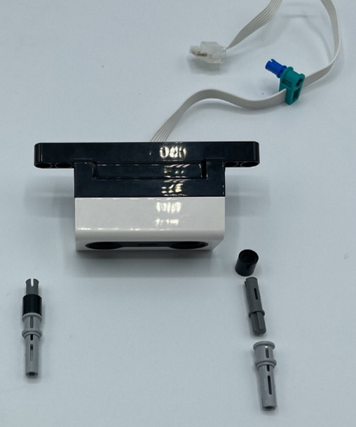
Figure 6.27 – Distant sensor attachment pins
Add these pieces to both ends of the black beam connected to the sensor:

Figure 6.28 – Pins added to the beam
Attach this sensor piece to the 7x11 open frame:
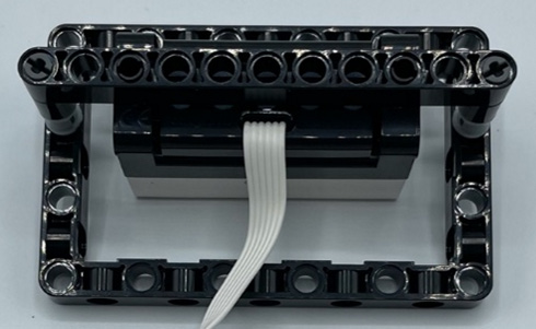
Figure 6.29 – Open frame attached to the pins
Take two more gray connector pins and attach them from the back of the open frame in both of the bottom corners:
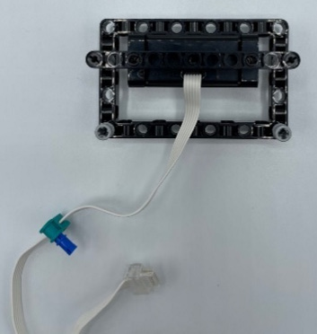
Figure 6.30 – Gray pins added to the open frame
This is how the piece should look before you add the remaining components:

Figure 6.31 – Front view of the sensor
Locate the following pieces to build out the front of the distance sensor frame:
- Two black 5x7 open frames
- Two black connector pins
- Two black 7L beams
- Two blue connector pins
Begin this portion of the build by adding a black connector pin to one of the 5L sides of the open frames:

Figure 6.32 – Pins added to the open frames
Attach both these open frames to the pins on the sensor attachment using the gray pins that are available:
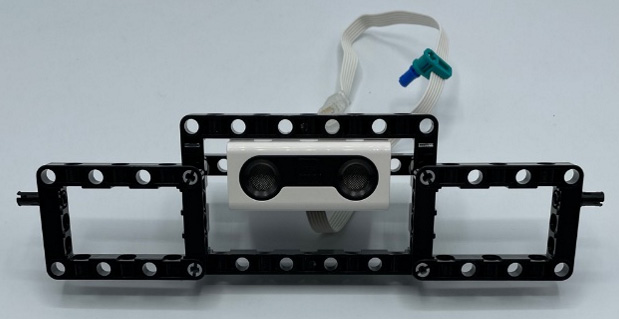
Figure 6.33 – Distance sensor attachment complete
Now that those have been added, let's turn to the beams. Add a blue connector pin to each of the black 7L beams:
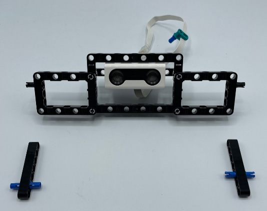
Figure 6.34 – Beams with connector pins
Add a beam to either side of the open frames you just attached to the distance sensor:
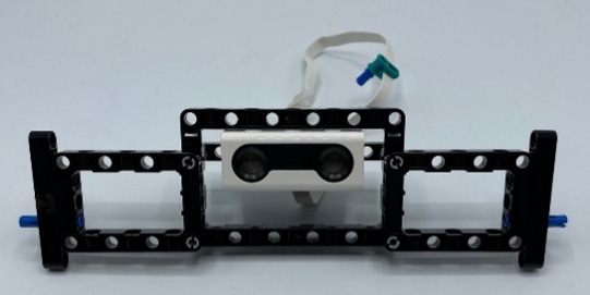
Figure 6.35 – Beams added to the sensor attachment
Finally, you will finish the front of the robot by building out the rest of it. This will help you achieve a square and secure body frame.
You will need the following pieces:
- Eight black connector pins
- Two small curved white panels
- Two medium curved white panels
Begin by adding black connector pins to all the white panel pieces, as shown in the following image:

Figure 6.36 – Bumper panel layout
Secure them all together into one piece:
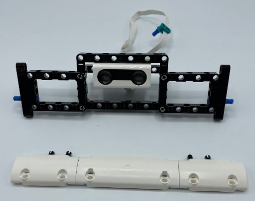
Figure 6.37 – Bumper panel pieces put together
Next, you must add this bumper piece to the front of the robot using the white elements. This will create a mini plow of sorts, which will protect your robot from being flipped. The robot will also be able to use it as a plow to hopefully lift your opponent as you continue to push them backward, out of the arena:

Figure 6.38 – Bumper panel added to the distance sensor frame
At this point, you should have these two parts of your robot built and complete:
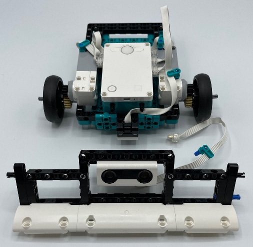
Figure 6.39 – Robot body and distance sensor build
Now, go ahead and connect it to the front of the robot. This front piece goes over the color sensor and keeps it out of view.
Take your time and work your wires toward the Intelligent Hub, ensuring they don't come into contact with the wheels and gears. Also, ensure the wires don't drag on the ground and accidentally slide under the color sensor. Use the wire clips to keep the wires up and out of the way:

Figure 6.40 – Front plow attachment installed
Let's turn the robot around and complete the backside and bumper of the robot now that the front is complete:
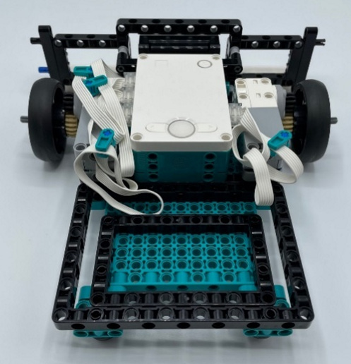
Figure 6.41 – Backside of robot
Let's move to the back to build out the back bumper so that our robot is prepared for an attack from either side.
Building the back bumper
You will be creating a similar structure to what we created for the front of the robot, with the exception that there will be no sensors to serve as a plow and bumper.
You will need the following pieces:
- Two black 5x7 open frames
- Two black 2x4 L beams
- Eight black connector pins
You will start by adding four black connector pins to the 5x7 open frames. On the outside of each frame, attach the 2x4 L beams, ensuring they're facing up:

Figure 6.42 – Open frames with L beams on the outside
Proceed to add each of the open frames to the larger open frame of the robot itself:
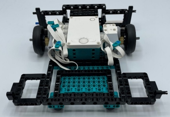
Figure 6.43 – Open frames added to the robot's body
Next, you need to add some structure and support for the robot. To do this, you will need the following:
- Two black 11L beams
- One teal 5L beam
- Eight black connector pins
Add these three pieces to the top of the open frames already on the robot. These beams serve as a support structure. Use the black connector pins to hold them all in place:

Figure 6.44 – Beam support for the open frames
Now, you must add the plow bumper to the back. You will need the elements laid out in Figure 6.45 and assemble them as shown. The back bumper will be less of a plow and more of a protector for if you are attacked from behind by your opponent. The rounded aspect of the white pieces will also serve as a plow that could potentially lift your opponent up.
One detail to pay attention to is the teal 3x3 piece. You will see that you are only using one connector pin on each side instead of two. The spacing of the pin holes doesn't allow for two connector pins on each side, so you will be using one on each side and slightly tilting this piece so that it flows with the white elements.
You will need the following pieces:
- Three teal 9L beams
- 12 black connector pins
- Two white curved white panels
- One teal 3x3 Technic piece
- Two black 11L beams
- Two blue connector pins
Here's how these pieces all go together:
- Start with three teal beams laid out across your workspace.
- Using three black connector pins, attach the white curved panels to the outside teal beams.
- Connect these white pieces together using two black connector pins and a teal 3x3 piece between them. The teal piece will be slightly angled.
- Using a blue connector pin and black connector pin, add a black 11L beam to the top of each of the white curved panels. Do this on both sides:

Figure 6.45 – Back bumper elements
Here is what this bumper piece will look like when it's been built:
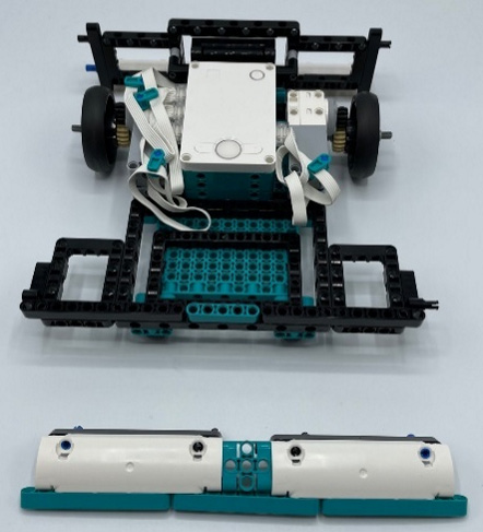
Figure 6.46 – Back bumper complete
Once that bumper has been built, it will connect to the back of the robot and provide a nice layer of protection, keeping another robot from getting underneath your robot. The bumper should be on the ground or very close to it as the wheels move around. Take the time to test your wheels and make sure everything still moves properly. A fine line of spacing is needed to keep everything moving smoothly:
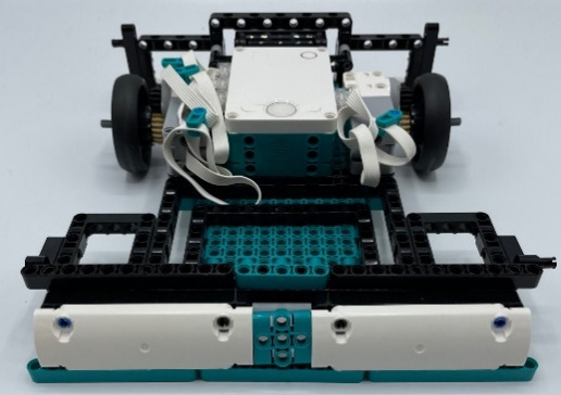
Figure 6.47 – Back bumper attached
There's one last step, and that is to secure the sides and secure the robot so that it has a strong square protection frame. Let's dive into this final step of building.
Strengthening the frame with outside supports
To start, we will create the same side panels. The only difference will be in the color of the 1x5 Technic beams on each side. One side will be all teal, while the other will be all black. You could alternate colors if you wish.
Essentially, you are building two copies of the same build, but the L pieces will be on the opposite sides of the 7L beams.
You will need the following pieces:
- Four black 3x5 L beams
- 16 black connector pins
- Two white panels
- Six black 5L beams
- Six teal 5L beams
- Four black 7L beams
- 16 blue connector pins
Here's how these pieces all fit together. Use Figure 6.48 to see the layout of the parts if a visual helps:
- Add two black 3x5 L beams to the inside of a white panel using four connector pins.
- Add a 5L beam to the white panel using two blue connector pins.
- Slide another 5L beam into the blue connector pin.
- Add four more blue connector pins to another 5L beam and attach it to the previous beam.
- Slide two more 5L beams into the blue connector pins.
- Add two black connector pins to your last beam and attach it to the five beams that are already connected.
- Attach another white panel to this beam using two black connector pins.
- Using two more blue connector pins, add two 7L black beams to complete the build:
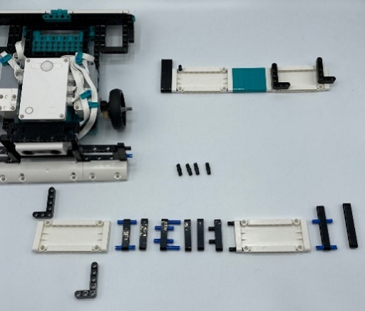
Figure 6.48 – Side panel construction
Here is what your two panel pieces will look like once they've been put together. Note how they are the same builds but have opposite layouts so that you can work on either side of the robot:
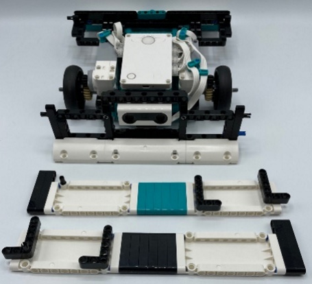
Figure 6.49 – Side panel pieces complete
Looking from a top view, here is how these panel pieces will connect to the sumobot:
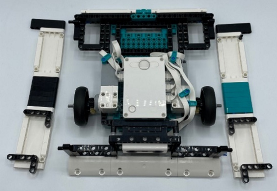
Figure 6.50 – Side panels alignment
The panels click and connect to the front and back using the L beams that are already on the back bumper and the 7L beams on the front:
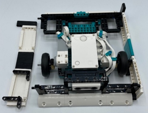
Figure 6.51 – Side panel installed
The one critical detail is the positioning of the axle of the wheels. The axle needs to be placed in the proper hole; otherwise, the robot will have problems moving. Be sure to insert the axle into the second to top hole of the black 3x5 L beam. This provides proper clearance off the ground and also keeps the tension where it should be, keeping the gears from spinning out or not moving at all:
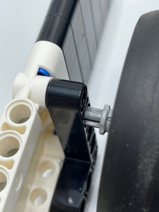
Figure 6.52 – Wheel axle alignment
Here is how your sumobot should look at this point:
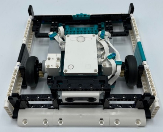
Figure 6.53 – Sumobot build checkpoint
The last step is to finish off the square frame by adding structural support. Using beams, you will secure the sides to the front and back, as well as provide strength all around by adding two layers of beams until everything is balanced out.
You will need the following pieces:
- 17 black connector pins
- One black round connector
- Two black 11L beams
- Two black 3x5 L beams
- Two black 15L beams
- Two black 7L beams
Begin by adding the black round connector to the middle pin of the teal piece on the back of the sumobot, opposite the distance and color sensors:

Figure 6.54 – Round connector added to the teal beam
Using two black connector pins per beam, attach the 11L black beams to either side of the round connector:
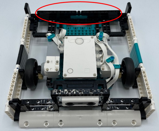
Figure 6.55 – Black beams added to the sides of the round connector pins
Using two more black connector pins for each black 3x5 L beam, add an L beam to either side of these beams:
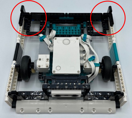
Figure 6.56 – L beams added
Using the 15L black beams and two black connector pins, add these to the side walls to strengthen the panels:
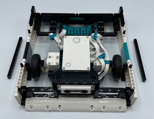
Figure 6.57 – Beams added to the side panels
Finally, add a black 7L beam to either side using two more black connector pins to finish up the first layer of support:
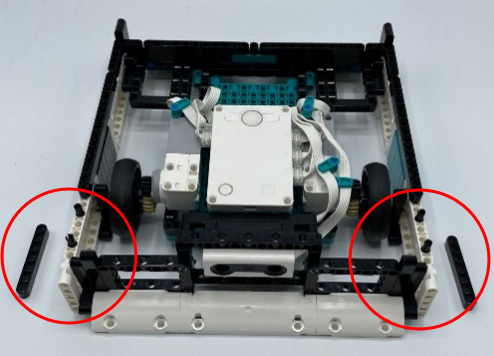
Figure 6.58 – 7L beams added to the side panels
Here is the first round of structural support:
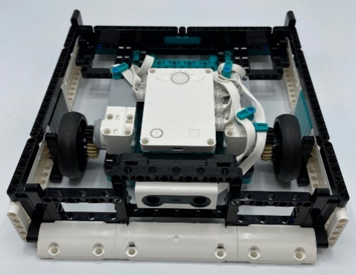
Figure 6.59 – First layer of strengthening the frame
You need to add one more layer of support to bring structural support and to smooth everything out. You will need the following pieces:
- Two black 7L beams
- One black 15L beam
- Six black connector pins
Begin the second layer by adding six black connector pins across the back:
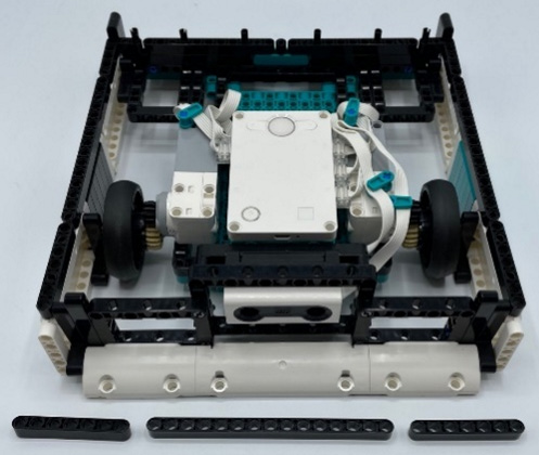
Figure 6.60 – Adding six pins to the beams
Then, add the beams to the pins:

Figure 6.61 – Beams added to the pins
The next step is to add a layer to each side. Due to part constraints, here is what you will need:
- 18 black connector pins
- Two blue axle pins
- Two black 2x4 L beams
- Two black round connectors
- Two black 15L beams
- Four black 3L beams
You will make the same build on either side of the robot supports. You will use the same pieces on either side. Note that the blue axle pin is for the axle hole of the 2x4 L beam. The rest are all using the black connector pins to hold all the pieces together. The following image showcases how they line up on the sides:
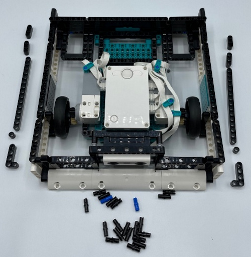
Figure 6.62 – Parts and layout for side panel support
Here is the second layer of black Technic beams:
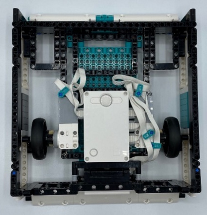
Figure 6.63 – Second layer of strengthening the frame
Now, you have one awesome sumobot ready to be coded so that you can put it to work in the arena!
Here is the back view of the sumobot:
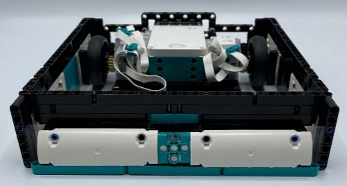
Figure 6.64 – Back view
Here is the front view of the sumobot:
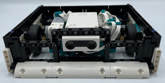
Figure 6.65 – Front view
Here is the side view of the sumobot:
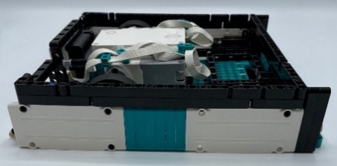
Figure 6.66 – Side view
Whew! You have done it. That's one sharp-looking and effective sumobot. Now, it is time to write some code so that you can compete in the arena.
Writing the code
The code for this project needs to solve a few key issues when it comes to sumobot battles and the strategy we are focusing on. Here are the three main goals of the code that you will be writing:
- The robot needs to stop when it sees white to keep it from driving out of the arena.
- The robot needs to detect when another robot is close so that it can push them forward and drive them out of the arena.
- The robot needs to be steady and consistent to avoid any unnecessary movements that may cause our robot fall out of the arena.
Let's double-check our ports and start writing the code to achieve these goals.
The ports
Before you write your code, it is good to make sure all the motors and sensors are plugged in properly. Using Port View, you can double-check the proper ports. The wheel motors will need be plugged into ports E and F. The distance sensor needs to be plugged into port A. The color sensor will need to be plugged into port C.
Additionally, you might need to change the settings of the distance sensor to inches and the color sensor to reflect any light if you have any issues with the code later:

Figure 6.67 – Port view in the MINDSTORMS software
Now that you know everything is plugged in properly, it is time to code.
Sumo robot program
To get started, you need to open the coding platform. Here are the steps in case you need to know how to open a new block coding program:
- Open the MINDSTORMS software.
- Click on Projects at the bottom of the menu bar.
- Scroll down to Other and click on Create New Project.
- Choose to make a Word Blocks program.
Main code sequence
The program has three main sections. You will build them step by step. Let's start with this first section of code. You can see it in Figure 6.68. The steps to create this code are as follows:
- Sumobot matches begin with a countdown. You will add a 3-second countdown timer using the purple light blocks. We will display a number each second that will count down 3-2-1. You can design your own numbers, shapes, or symbols. This gives the participant time to back away from the arena before the battle begins:

Figure 6.68 – 3-2-1 countdown
- You will create a variable called Action that will be used to change the conditions of the variable based on sensor inputs. Once you create this variable, go ahead and add a block that sets the action to option 1 by using the set variable block. This can be found in the variable orange coding blocks:
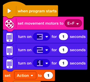
Figure 6.69 – Creating the Action variable
- Go to the Control blocks and drop in a Forever block under the Set Action to 1 block we just added in step 2. This Forever block will help our robot keep making decisions until we stop the code.
- In the Forever block, you will add four of the same types of code chunks. You will drop in an If block with a green operator block to compare the variable to a number. Write this out so that we have four actions numbered 1, 2, 3, and 4.
- For Action 1, you will simply have your robot move forward by adding the Start Moving block, which can be found in the pink More Movement blocks. Keep the speed low to begin with; you can always go back and adjust it to your liking:
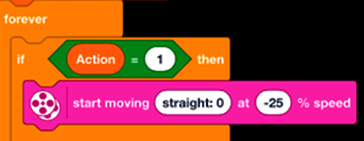
Figure 6.70 – Action 1 decision
- For Action 2, you will write a command for when the color sensor detects the white perimeter. It will back up for two rotations and randomly move in a certain direction before being told to go back to Action 1 of moving straight. Again, you can dial this into your liking and adjust how you want your robot to respond when it detects the edge, but for now, you will just have the robot move back for two rotations:
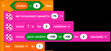
Figure 6.71 – Action 2 decision
- For Action 3, you will write some code that makes the robot move fast and push the other robot forward. This action will be linked to the distant sensor when it detects another robot. A sound has been added to help you audibly know when your robot detects the opponent. This is a useful tip to help refine and make sure your robot is doing what you want it to do. Again, once it pushes forward, it kicks back to Action 1 to make another decision. It will repeat this step until the sensor no longer detects the opponent:

Figure 6.72 – Action 3 decision
- For Action 4, you need the robot to be able to detect an opponent and also detect the white perimeter. You don't want to accidentally push yourself off the arena. Again, this will need to be further tweaked to your liking, but for the sake of this example, this code will have the robot back up for one rotation to avoid the edge, reset to Action 1, and make another decision:
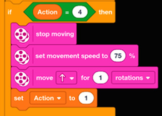
Figure 6.73 – Action 4 decision
Here is what the code looks like once it's completed:

Figure 6.74 – Main part of the program
Double-check your code and if it looks good, then it is time to code the color sensor.
Color sensor code sequence
We need another little chunk of code for the main program to help with decision making. This one focuses on the color sensor. Let's get started:
- Drop in another yellow Events block called When Program Starts. You will have several parts of code running at the same time.
- Insert a Forever block into this code.
- Insert an If block so that it's nested in the Forever block.
- Using a sensor block, you will dial in your sensor to the reflection light. You can try using colors that are only black and white, but I have found that these new color sensors are so good that a speck of white dust or chipped paint can activate the sensor. I stick with reflection light, and you can adjust the percentage based on the ambience of the space. To do this, simply place your robot on a black surface and see what percentage reading it provides; then, do the same when it sees a white surface. Change the percentage number on this blue sensor block accordingly.
- When it detects white, add the variable block to change the action variable to the number 2. This will activate that sequence of code in the main part of the coding we just completed earlier:

Figure 6.75 – Color sensor program
Double-check your code and if it looks good, you can start programming the distance sensor.
Distance sensor code sequence
You need to write some code for when the distance sensor senses an object within a certain range so that you can deploy an attack strategy. Let's do this now:
- Drop in another yellow Events block called When Program Starts. You will have several pieces of code running at the same time.
- Insert a Forever block into this code.
- Insert an If block so that it's nested in the Forever block.
- Using a sensor block, you will dial in your sensor to the distance of your choice. Try different distances to find what works. In my test runs, 6 inches was pretty spot on as that activated when I needed it to at all times, while also not being triggered by objects outside the arena.
- When it detects an object, add the variable block to change the Action variable to the number 3, which will then activate that sequence of code in the main part of the coding we just completed earlier.
- Insert another If block so that it's nested in the Forever block and underneath our first If block.
- This If block will contain an operator block waiting for two variables to trigger the code. In this case, we need the distance sensor and the color sensor to be activated. When this happens, our robot will make a fourth decision to prevent itself from falling off the edge while battling a robot.
- Drop in another Set Action block with the condition of 4 to activate that code sequence in our main program:
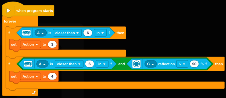
Figure 6.76 – Distance sensor program
In the end, the entire code will look like this:
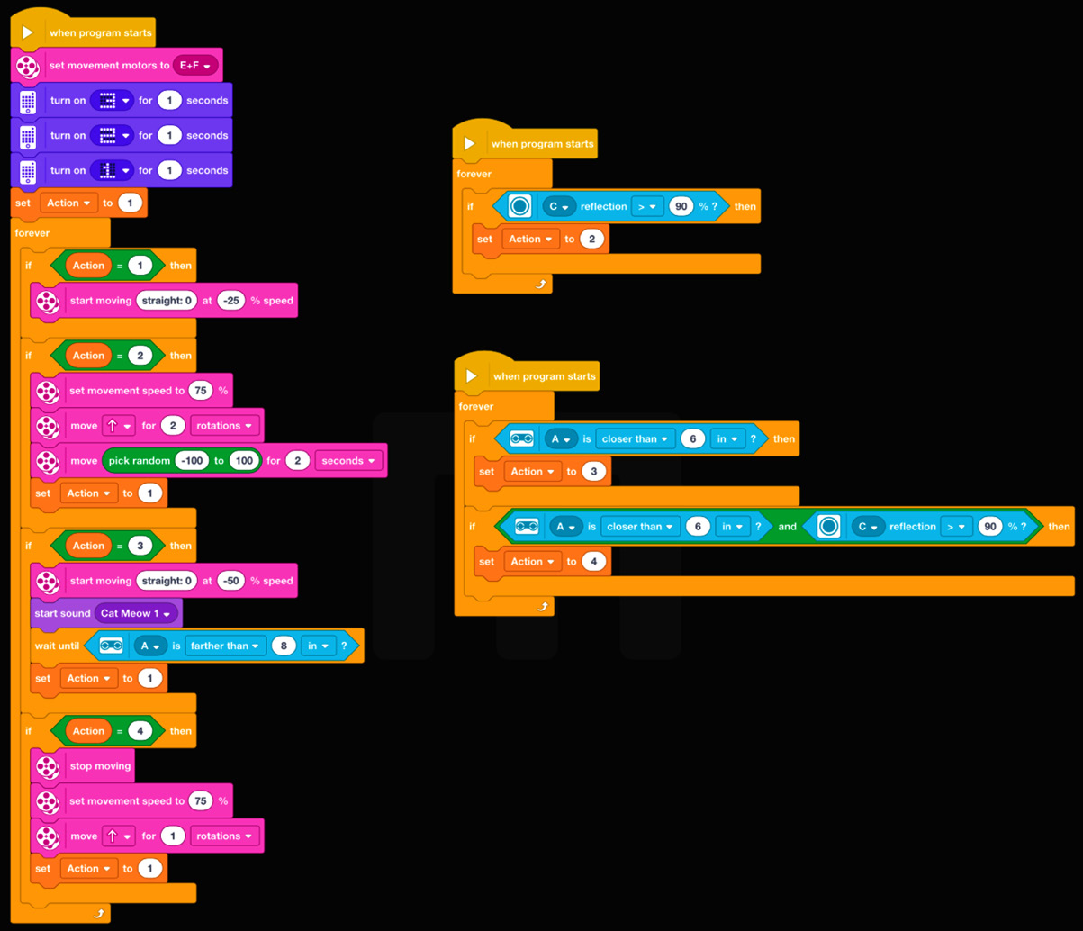
Figure 6.77 – Distance sensor program
And you have done it! You should now have a working sumobot that is full of potential and has places for you to add your own flavor and design ideas. Enjoy!
Make it your own
Now, it is time to hand the robot over to you. This is where you can take what you have built so far and customize the robot to your liking. Plenty of pieces have been left in the bin for you to design aesthetic features and apply new approaches to make your robot more intuitive, and there are plenty of coding options you can utilize to take the robot to the next level.
Here are a few ideas to consider:
- The kit itself is limited in terms of the sensors that can be plugged into the Intelligent Hub. If you have another sensor from another kit or SPIKE Prime, then you could add a distance sensor, force sensor, or even a color sensor to the pack to create another decision point in the code so that when the robot senses danger from behind, it can counter. Currently, the robot is dependent on being strong enough to handle an attack from the back to counter and win.
- If you wanted to take a different approach, what if you designed a device that, when the robot is hit from behind, could trigger a counterattack?
- Cosmetic appeal. There is plenty of open space at the back and top to fully customize this robot. How can you take the out-of-the-box parts and add some personality to your robot?
Summary
In this chapter, you explored the concepts of gears, sensors, making various decisions based on feedback, and how to use simple engineering principles to build an effective robot. This chapter was focused on providing you with building and coding concepts related to how you can use the different components that are available in the Robot Inventor Kit, as this will help you build a strong sumobot model with high torque and stability via gearing mechanisms. Additionally, you used sensors to trigger the different actions of your sumobot. This ensures that you will have success in battles. You did this by identifying the border of the arena and stopping the sumobot from falling off the edge, as well as using the distance sensor to activate attack mode when your competition is within striking distance.
Now, it is time to engage in a battle. Find a friend, foe, or local competition and see how you do. Feel free to battle other types of robots as well. There are so many ideas, rules, and suggestions online for you to use to explore and expand your sumobot building and strategy deployment. Good luck. There are so many possibilities, so take the time to try new ideas, attachments, sensor placements, and more. In all my years of robotics, sumobots is the one challenge that people love the most. I think you will too!
In the next chapter, you will use gearing again, but for a different purpose: trying to achieve maximum speed. Let's rev our engines and get started by building and racing a dragster!