
The Mechanics of Solar Power
This chapter provides an overview of solar power and the mechanisms regarding how energy is produced by the various systems.
PV systems work by converting the sun rays through the PV effect. Capturing electrons that are released as sunlight is absorbed by materials such as silicon completes this process. The energy produced is DC, which needs to be converted to alternating current for most applications through an inverter.
Manufacturing PV panels, which are the most prevalent in the market, is a complex process that includes chemistry, engineering, and precision work. The elements are combined, electrical connections are made, and the panels are fastened to a racking system.
Other important technologies, such as various thin films and CSP systems are explained, including parabolic trough, power tower, and Fresnel reflectors.
Keywords
Photovoltaic; Fresnel; power tower; parabolic trough; ingots; wafers; silicon; concentrated PV; thin film; racking
A basic primer on the mechanics of solar power generation is important in order to develop the foundational knowledge required to properly consider the economic and workforce trends of the solar industry. This chapter provides an overview of how each of the various technologies (PV, thermal, etc.) work. It is neither as exhaustive as a scientific textbook on the subject nor is it as simple as a glossary entry; rather it provides the introductory knowledge base that is a prerequisite for analyzing and considering the industry as a whole.
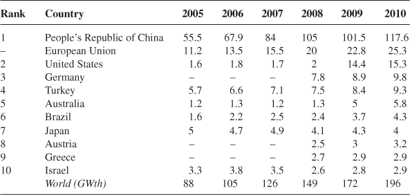
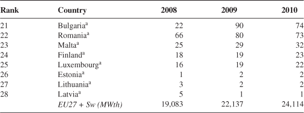
Installed Capacity

aCSP Facts & Figures. Csp-world.com (retrieved 22.04.13).
bConcentrating Solar Power. irena.org, p. 11.
cEuropean Photovoltaic Industry Association, 2013. Global Market Outlook for Photovoltaics 2013–2017.
Source: CSP: https://en.wikipedia.org/wiki/Concentrated_solar_power; PV: http://en.wikipedia.org/wiki/Photovoltaics.
Photovoltaic
At its most basic level, solar PV technology converts sunlight to energy. This conversion happens directly through solar cells made up of various components that produce the photoelectric effect. This phenomenon occurs when electrons are emitted from materials as they absorb light energy. Though early PV cells were made of silver selenide or copper, silicon has been the predominant substance used for the past 60 years.1
Total PV Peak Power Capacity (MWp)a
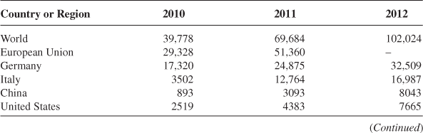

aBP Statistical World Energy Review 2011 (XLS). EurObserv’ER 202: Photovoltaic Barometer (retrieved 8.08.11).
Source: http://en.wikipedia.org/wiki/Solar_power_by_country.
Solar cells produce DC power, which fluctuates based on the sun’s intensity. This is why cloud cover, seasonal angle of the sun, and therefore latitude, and new solar tracking systems have such dramatic impacts on generation. Typically, cells are cut from large segments of bulk material called wafers and processed as semiconductors.
These cells are connected together to form modules. A module is what most people would identify as a solar panel. Modules are connected to form arrays, which would represent the aggregate of panels on a rooftop installation. Finally, in order to be connected to a grid, inverters convert the DC to alternating current (AC).
The Manufacturing Process
Much of solar PV systems’ current price structure is based on the supply of materials and the efficiency of the manufacturing process. Other important considerations, covered later in this book, are consumer demand, government policies and incentives, the availability and cost of capital, raw materials and component pricing, and labor availability and wages.
The solar manufacturing process begins with raw materials and in the case of most traditional panels that material is either monocrystalline or polycrystalline silicon. Silicon is mined, typically from sand or sandstone, and is the second most abundant material on earth. Any grade school student could easily identify it as quartz!
The mined material, silicon dioxide, is readily available, yet must go through an extensive purification process to be used in solar applications. Purification is conducted in multiple steps. First, the material is heated in a furnace to release the oxygen and separate the carbon dioxide from the molten silicon. This 99% pure silicon is then “purified even further using the floating zone technique. A rod of impure silicon is passed through a heated zone several times in the same direction. This procedure “drags” the impurities toward one end with each pass. At a specific point, the silicon is deemed pure and the impure end is removed.”2
Using the Czochralski method, a crystal of silicon is used as a seed, dropped into polycrystalline silicon, and a large, pure, cylindrical ingot of silicon results. Ingots of raw materials are, in the case of polycrystalline cells, cut into wafers that are thin slices that are polished and treated with doping agents (as are most semiconductors). Doping agents are simply impurity atoms that create either p-type which has extra holes or n-type which contains excess free electrons. The junctions of these regions are called p–n junctions and their purpose is to increase the conductivity of the cell.
Cells then receive metal contacts and are connected to other cells to create modules. These contacts are typically joined with tin and copper connectors.
The cells then go through several processes to reduce reflectivity and increase absorption of light. Nearly all cells receive an antireflective chemical coating, which is typically silicon nitride. Also, some cells are textured for to reduce reflective properties.
Finally, modules are encapsulated in a silicon- or vinyl-based compound and cased in aluminum or other lightweight metal frames. These frames typically receive construction grade Mylar backing and are capped with glass.
Given these complex processes, the finished product assembly as illustrated above only represents a small fraction of the solar manufacturing industry. Component manufacturers in photovoltaics may be involved with the production of
Thin Film
While traditional PV mono- or polycrystalline cells make up the majority of the PV market, thin film solar is gaining ground, particularly in the United States. Thin film technology has a multitude of benefits and chief among them is lower cost. However, the transition to thin film has not been smooth, despite the technology having been in use in calculators and watches for decades, and significant improvements in efficiency must be gained before thin film encroaches on traditional PV’s market share.
At about 1/350th the thickness, thin film solar panels are obviously manufactured quite differently from traditional PV cells. Rather than the material-intensive identified above, thin film is produced by applying single layers of semiconductors on a substrate—most typically glass, or sometimes metal or plastic. This thin sheet is lighter, cheaper, yet less efficient than the thick wafer cells.
Thin film technology has been around for decades. Solar-powered calculators and other small devices have used amorphous silicon (a-Si) thin film to charge their tiny batteries for decades. However, in large-scale applications, researchers have been unable to increase the efficiencies enough to make a-Si systems on a larger scale more competitive.
However, several alternative technologies are promising—if not yet ready to replace traditional PV systems. These nonsilicon-based technologies have the added benefit of relying on materials that are more readily available and less volatile.
The most promising new thin film technologies use either copper indium gallium deselenide (CIGS) or cadmium telluride (CdTe). There are two basic configurations of the CIGS solar cell: the CIGS-on-glass cell requires a layer of molybdenum to create an effective electrode. This extra layer isn’t necessary in the CIGS-on-foil cell because the metal foil acts as the electrode. A layer of zinc oxide (ZnO) plays the role of the other electrode in the CIGS cell. Sandwiched in between are two more layers—the semiconductor material and cadmium sulfide (CdS). These two layers act as the n-type and p-type materials, which are necessary to create a current of electrons.3
The newest process for manufacturing thin film solar is best described in the illustration of San Jose, CA based Nanosolar, Inc. manufacturing process.
Nanosolar makes its solar cells using a process that resembles offset printing. Here’s how it works:
1. Reams of aluminum foil roll through large presses, similar to those used in newspaper printing. The rolls of foil can be meters wide and miles long. This makes the product much more adaptable for different applications.
2. A printer, operating in an open-air environment, deposits a thin layer of semiconducting ink onto the aluminum substrate. This is a huge improvement over CIGS-on-glass or CdTe cell manufacturing, which requires that the semiconductor be deposited in a vacuum chamber. Open-air printing is much faster and much less expensive.
3. Another press deposits the CdS and ZnO layers. The ZnO layer is nonreflective to ensure that sunlight is able to reach the semiconductor layer.
4. Finally, the foil is cut into sheets of solar cells. Sorted-cell assembly, similar to that used in conventional silicon solar technology, is possible in Nanosolar’s manufacturing process. That means the electrical characteristics of cells can be matched to achieve the highest panel efficiency distribution and yield. CIGS-on-glass solar panels don’t offer sorted-cell assembly. Because their panels consist of cells that are not well matched electrically, their yield and efficiency suffer significantly.4
This process is critical because it lowers the price, which is necessary given the market perception of lower overall efficiency of thin film. Traditional solar is reaching about 25% maximum efficiency while CdTe and CIGS are now reaching 15–20%. Further investment in these technologies, as illustrated in Chapter 5, will increase these efficiencies further, drive down manufacturing costs, and increase the feasibility for many applications.
Concentrated Solar Energy
Unlike traditional and thin film PV applications that absorb natural light from the sun, CSP systems work by using mirrors or other reflectors to intensify the sun’s rays prior to collection. CSP is growing at a rapid pace due to its feasibility for larger systems—typically utility-scale systems. By the end of 2017, CSP is expected to generate about 10.9 GW of power globally and 4.2 GW in the United States (#2 behind Spain) alone.
The current nomenclature in use to describe concentrating systems can be confusing and quickly becomes riddled with jargon when referring to concentrated photovoltaics (CPV), CSP, and solar thermal energy. A basic explanation is:
• CPV use mirrors to concentrate the PV effect. CPV is generally not included in the discussion of CSP and is clearly not a solar thermal energy.
• Solar thermal refers to generating heat energy from the sun. This heat energy can be used for space heating, water heating (for pools, domestic hot water, or forced hot water heating systems for instance), or electrical production (typically CSP).
• CSP refers to a variety of technologies that transfer heat energy from the sun to generate electricity.
A summary of each is described in the following sections.
Concentrated Photovoltaics
As its name suggests, CPV uses mirrors or lenses to concentrate light to a smaller but more intense beam. This concentration allows for fewer, smaller panels. Because fewer panels are required, more costly, higher efficiency panels are feasible for the application.
Despite this cost savings, CPV has added costs that are not typical of a traditional PV system. These costs include the concentrating medium (mirrors, glass, lenses, etc.), tracking equipment, and cooling equipment due to the high heat generated from the concentrated rays. Despite capturing only a small fraction of the overall solar market, forecasts for the technology are strong.
Capital costs for CSP plants continue to fall, making the technology more competitive with fossil-fuel generation. In fact, capital costs for CSP plants without thermal energy storage can be as low as $4600/kW, while plants with between 6 and 15 h of thermal storage can carry capital costs as high as $10,500/kW.5 This point is critical because it is becoming evident that CSP can only compete with PV on its storage potential.6
A recent article by Dino Green refines the point, stating: “energy investors consider competitive cost of energy the most important issue. That is why in 2011 in the US we have seen a sudden shift from planned CSP power plants being converted to Photovoltaic (PV) – this trend continues in 2012. As long as energy price of PV plants is less than the Energy price of equivalent CSP, and continue to decline, PV will remain a preferable solution over CSP for energy investors. CSP systems will need to demonstrate high performance in all three attributes, competitive thermal-energy-storage costs, energy dispatch-ability and reliability as an ancillary solution, in order to remain attractive and competitive against Photovoltaic panels.”7
This is particularly important given PVs declining installed cost per watt and much cheaper operation and maintenance costs, as these costs for CSP plants range from $0.02 to $0.035/kWh.8
Solar Thermal Energy
Solar thermal energy refers to heating water with the sun, a practice that has been used by humanity for thousands of years. As the technology has progressed, the United States Energy Information Administration has classified the collectors as low, medium, and high temperature, obviously based on heat output. Generally speaking, low- temperature collectors are used for heating swimming pools or for solar heating and cooling, which utilized heat pump technology as part of a comprehensive Heating, Ventilation, and Air-Conditioning (HVAC) system. Because of their limited use, this text does not address the technology in detail.
Medium-temperature collectors, on the other hand, make up the vibrant and growing solar water heating segment of the industry that supplies hot water for residential and commercial applications. These collectors are able to generate significantly more heat, which is important for applications that require heating to 125–140°F (as opposed to 70–80°C for a pool).
Solar water heating has been shown to be an effective means to supplement traditional water heaters, particularly in southern climates—though their application, with a few tweaks, is effective in even the northernmost reaches of the United States. In the United States, solar water heating is recovering from a bad reputation, mostly driven from poor installation quality in the 1970s in California. However, solar water heating systems are used widely throughout Australia, Europe, Asia (and in particular, Japan), and the Middle East. China is by far the fastest growing location for solar water heating installations representing between 60% and 80% of annual installations globally.
Solar water heating is much more effected by climate than PV, as ambient temperature, overheating and freezing protection, and other consideration can dramatically impact required and actual output for the systems.
The type, complexity, and size of a solar water heating system are mostly determined by
• Changes in ambient temperature and solar radiation between summer and winter.
• The changes in ambient temperature during the day–night cycle.
• The possibility of the potable water or collector fluid overheating.
• The possibility of the potable water or collector fluid freezing.9
The major reason for this is to protect the systems (and users) from overheating and freezing. While there are many technologies that can allow for draining or passive heat loss (typically at night) for direct systems, one important technological breakthrough is the development of indirect systems.10
The most basic technology for solar water heating is the Integrated Collector Storage (ICS) or batch collection system. The collectors are markedly low tech and inexpensive, and basically serve as water tanks inside an insulated oven that is heated by the sun. Though generally low efficiency, they can be used effectively in warm, sunny regions with less heat loss and without freezing temperatures in the winter.
Flat plate solar thermal collectors use pipes (called headers and risers, depending on size and orientation) to increase heating efficiency. These systems are generally used as direct systems (heating potable water) and often used tempered glass to withstand storm debris and hail. Some of these systems include evacuated tube collectors, which use a vacuum (and some different materials) to reduce heat loss. While this reduction can be significant, the evacuated tube collectors (ETC) is less efficient in full sun applications and has had issues with reliability.
Global Cumulative CSPa,b and Yearly Installations (MWp)

aCSP Facts & Figures. Csp-world.com (retrieved 22.4.13).
bConcentrating Solar Power. irena.org, p. 11.
Source: https://en.wikipedia.org/wiki/Concentrated_solar_power.
The highest temperature systems are used for electrical generation, which is known as CSP. CSP systems operate like many other electrical power plants generating power from steam-driven turbines. However, unlike most power plants that generate the steam from fossil fuels or nuclear reactors, CSP systems use focused solar energy to heat the water. As an added benefit, the systems’ direct product is heat, which is significantly cheaper and easier to store than electricity. This is important because it allows CSP systems to produce power after the sun goes down.
CSP continues to grow at a record pace despite fierce competition from PV systems. The most recent data at the time of printing suggests that 938 MW of CSP will be commissioned by the end of 2013 in the United States.11 This is a staggering figure based on current installed CSP, and reflects the global growth of the market, where more than 20 GW of CSP capacity is currently under development worldwide.12
Investors may not be as willing to embrace CSP as they were 3–5 years ago, but the long-term trends still seem quite favorable. While PV developers have been able to focus on driving down the cost per watt of their modules, CSP developers have had many different components to work on. As each of these challenges finds a solution, the technology leaps. So much so that, according to IEA’s CSP technology roadmap estimates, total installed CSP capacity could reach 337 GW by 2030, tripling to 1089 GW by 2050.13
There are four primary technologies of CSP in current use: (1) parabolic trough; (2) power tower; (3) Fresnel reflector; and (4) stirling dish. Given the recent bankruptcy of stirling energy systems (SES), lack of competitiveness with PV systems, and, despite the highest efficiency rating of the four technologies, the future of stirling systems is suspect and is therefore not covered extensively in this text.
Parabolic Trough
Parabolic trough systems uses curved, parabola-shaped reflectors that use mirror coating to concentrate sunlight on a tube filled with liquid. This tube, frequently called a Dewar tube, is usually filled with oil and carries the heated fluid to an engine similar to a traditional power plant.
To reach its maximum thermal efficiency of 60–80%, parabolic reflectors are mounted on tracking systems to follow the sun. The intensity of the concentrated solar rays heats the liquid medium to approximately 400°C.
The future of the technology, in addition to overall component price declines, will depend on improvements in tracking technology. Currently, parabolic trough tracking systems are aligned to the vernal and autumnal equinoxes, meaning that for much of the year (and most dramatically at the summer and winter solstices) the concentration is not at peak. This results in systems that only reach about 1/3 of their maximum theoretical efficiency.
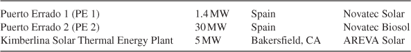
Parabolic Trough Global Applications

Source: http://en.wikipedia.org/wiki/List_of_solar_thermal_power_stations; http://en.wikipedia.org/wiki/Solar_power_tower.
Power Tower
While the overall principle is the same, the power tower design is completely different from the parabolic trough. Power tower systems, sometimes referred to as heliostat plants, vaguely resemble oil drills, yet produce clean power from the sun.
The technology is fairly basic and not as complex as the parabolic trough. A series of reflectors mounted on tracking systems, called heliostats, reflect sunlight to a central receiver on top of a large tower.14 This receiver, which typically contains liquid sodium, seawater, or other fluid, is heated to 500–1000°C. Power towers generally offer more efficiency than trough technology, are cheaper due to the use of flat, rather than curved, glass for the reflectors, and can store heat longer. As a result, the National Renewable Energy Laboratory (NREL) estimates that power tower systems should be able to produce electricity at 5.47 cents/kWh by 2020.15
Continued price declines are important for the technology, as it lags far behind parabolic trough systems. In fact, of the 1.9 GW of CSP installed through the first quarter of 2012, 1.8 GW were parabolic trough designs.
Power Tower (Heliostat) Global Applications

Source: http://en.wikipedia.org/wiki/List_of_solar_thermal_power_stations.
Fresnel Reflectors
Fresnel reflectors again use mirrors to focus light onto receivers to heat a fluid, which generates electricity via steam engine or heat pump. These mirrors can be curved or flat, and some use parabolic mirrors to enhance the effect. These systems differ from trough and dish systems because they use multiple mirrors focused on a single receiver (therefore allowing many different configurations to maximize their efficiency at different periods of the day and year). They differ from power tower because they operate on a single rather than dual axis.
Fresnel reactors have had a start and stop history, and there are few plants currently generating with the technology. Initially, the significantly lower cost of Fresnel technology led experts to believe it would outcompete trough designs, however, advances in nanotechnology and advanced manufacturing has narrowed the gap.
The most common designs are linear Fresnel reflector (LFR) and compact linear Fresnel reflectors (CLFR). These systems lower cost and increase output by using absorbers that share mirrors. The principal design flaw, however, is that shading is produced from adjacent reflectors, lowering the overall output of the system. This concern is reduced in CLFR technology, which uses more advanced tracking and situates components closer to the ground. CLFR systems typically use flat mirrors, which are also less expensive to produce, and uses multiple absorbers, maximizing the reflected light.
Fresnel reflectors utilize the Fresnel lens effect, which, unlike a standard mirror, consists of a reflector with a large aperture and short focal length. This inexpensive modification allows for greater intensity for significantly lower cost. Despite its name, however, the plants using LFR or CLFR technology are not using actual Fresnel lenses, however, prototypes are in development. These lenses, made of glass, are theoretically much cheaper to produce than lenses.
LFRs are in use in several global applications including:

1http://www.eere.energy.gov/basics/renewable_energy/types_silicon.html.
2http://www.madehow.com/Volume-1/Solar-Cell.html.
3http://science.howstuffworks.com/environmental/green-science/thin-film-solar-cell2.htm.
4http://science.howstuffworks.com/environmental/green-science/thin-film-solar-cell3.htm.
5http://www.irena.org/DocumentDownloads/Publications/RE_Technologies_Cost_Analysis-CSP.pdf.
6http://www.renewableenergyworld.com/rea/blog/post/2013/03/how-solar-pv-is-winning-over-csp.
7http://www.renewablegreenenergypower.com/solar-energy-facts-concentrated-solar-power-csp-vs-photovoltaic-pv-panels/.
8http://www.irena.org/DocumentDownloads/Publications/RE_Technologies_Cost_Analysis-CSP.pdf.
9http://en.wikipedia.org/wiki/Solar_water_heating, citing eere.energy.gov.
10Direct systems heat potable water in the collectors and store in a tank. Indirect systems heat a secondary, nonpotable fluid (often propylene glycol) that heats a tank of water.
11http://www.seia.org/research-resources/solar-industry-data.
12http://www.irena.org/DocumentDownloads/Publications/RE_Technologies_Cost_Analysis-CSP.pdf.
13http://www.irena.org/DocumentDownloads/Publications/RE_Technologies_Cost_Analysis-CSP.pdf.
14http://www.solarpaces.org/CSP_Technology/csp_technology.htm.
15Assessment of parabolic trough and power tower solar technology cost and performance forecasts (http://www.nrel.gov/solar/parabolic_trough.html).